
Related Manuals for Caple CR 1207


Summary of Contents for Caple CR 1207
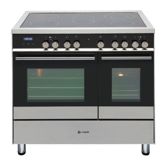
- Page 1 Instruction manual for range cooker Models code: CR 1207 - CR 9207 Contact Caple on 0844 800 3830 or for spare parts www.4caple.co.uk...
-
Page 2: Declaration Of Ce Conformity
Thank you for buying your new Caple cooker. To ensure that you get the best results from your new Caple cooker, we strongly suggest that you read this instruction manual thoroughly before use. This manual contains installation advice, cleaning tips and a cooking guide, as well as other important facts about your Caple cooker. - Page 3 IMPORTANT SAFETY PRECAUTIONS AND RECOMMENDATIONS IMPORTANT: This appliance is designed and manufactured solely for the cooking of domestic (household) food and is not suitable for any non domestic application and therefore should not be used in a commercial environment. The appliance guarantee will be void if the appliance is used within a non domestic environment i.e.
- Page 4 • Do not touch the appliance with wet or damp hands (or feet). • Do not use the appliance whilst in bare feet. • If you should decide not to use this appliance any longer (or decide to substitute another model), before disposing of it, it is recommended that it be made inoperative in an appropriate manner in accordance to health and environmental protection regulations, ensuring in par- ticular that all potentially hazardous parts be made harmless, espe-...
- Page 5 • WARNING: Danger of fire: do not store items on the cooking surfa- ces. • WARNING: When correctly installed, your product meets all safety requirements laid down for this type of product category. However special care should be taken around the rear or the underneath of the appliance as these areas are not designed or intended to be tou- ched and may contain sharp or rough edges, that may cause injury.
-
Page 6: Electrical Requirements
1 - Electrical Requirements WARNING! ELECTRICITY CAN BE EXTREMELY DANGEROUS. THIS APPLIANCE MUST BE EARTHED. For your safety please read the following information: This appliance must be installed by a qualified technician according with the current local regulations and in compliance with the manufacturer instructions. The appliance must be connected to the electrical network verifying above all that the voltage corresponds to the value indicated on the specifications plate and that the cables section of the electrical plant can bear the load which is also indicated on the plate. - Page 7 Electrical Installation - Wall box connection This appliance must be connected to a DOUBLE POLE SWITCHED double pole isolating switch (fig. 1.1) and FUSED SPUR OUTLET to the terminal block in the cooker (figs. 1.2, & 1.3) using the following guide: 1) The wire which is coloured brown must be connected to the terminal marked L (Live), or coloured Red.
-
Page 8: For The Installer
Fig. 2.1a The veneered synthetic material and the glue used must be resistant Model CR 1207 to a temperature of 90°C in order to avoid ungluing or deformations. Curtains must not be fitted immediatly behind appliance or within 500 mm of the sides. -
Page 9: Levelling The Cooker
Fitting the adjustable feet and levelling the cooker - Model CR 9207 The adjustable feet must be fitted to the base of the cooker before use. Rest the rear of the cooker on a piece of the polystyrene packaging exposing the base for the fitting of the feet. - Page 10 Levelling the cooker - Model CR 1207 The cooker is already fitted with four levelling feet. Level the cooker by screwing or unscrewing the feet (Fig. 2.5). Make sure you follow the instructions in Figs. 2.6a and 2.6b. Note: bolts are supplied with the cook- er in a separate kit.
-
Page 11: Moving The Cooker
Moving the cooker - Warning When raising cooker to upright position always ensure two people carry out this manoeuvre to prevent damage to the adjustable feet (fig. 2.7a - 2.7b). Fig. 2.7a Fig. 2.7b Warning Be carefull: do not lift the cooker by the door handle when raising to the upright position (fig. - Page 12 Anti-Tilt Bracket - Model CR 9207 Important! To restrain the appliance and prevent it tipping accidentally, fit a bracket to its rear to fix it securely to the wall. To fit the anti-tilt bracket: After you have located where the cooker is to be positioned, mark on the wall the place where the two screws of the anti-tilt bracket have to be fitted. Please follow the indications given in fig.
- Page 13 Anti-Tilt Bracket - Model CR 1207 Important! To restrain the appliance and prevent it tipping accidentally, fit a bracket to its rear to fix it securely to the wall. To fit the anti-tilt bracket: After you have located where the cooker is to be positioned, mark on the wall the place where the two screws of the anti-tilt bracket have to be fitted.
-
Page 14: Provision For Ventilation
Provision for ventilation – The appliance should be installed into a room or space with an air supply in accordance with BS 5440-2: 2000. – For rooms with a volume of less than 5 m - permanent ventilation of 100 cm free area will be required. -
Page 15: Gas Installation
3 - Gas installation IMPORTANT NOTE This appliance is supplied for use on NATURAL GAS or LPG (check the gas regulation label attached on the appliance). – Appliances supplied for use on NATURAL GAS: they are adjusted for this gas only and cannot be used on any other gas (LPG) without modification. -
Page 16: Gas Connection
Gas connection The installation of the gas appliance to Natural Gas or LP Gas must be carried out by a suitably qualified and registered person. Installers shall take due account of the provisions of the relevant British Standards Code of Practice, the Gas Safety Regulations and the Building Standards (Scotland)(Consolidation) Regulations issued by the Scottish Development Department. - Page 17 Model CR 9207 Left gas Right gas inlet pipe inlet pipe Fig. 3.2 Plug Model CR 1207 Left gas Right gas inlet pipe inlet pipe 1/2” BSP (male) Fig. 3.1a Plug 1/2” BSP (male)
- Page 18 Important prescriptions for gas connection Model CR 9207 Rear wall Fig. 3.3a Suggested area for gas mains connection Model CR 1207 Rear wall Fig. 3.3b Suggested area for gas mains connection...
-
Page 19: Conversion To Natural Gas Or To Lpg
Conversion to Natural Gas or to LPG Injectors replacement of top burners Auxiliary and Semi-rapid Every cooker is provided with a set of burner injectors for the various types of gas. Injectors not supplied can be obtained from the After-Sales Service. Select the injectors to be replaced accor- ding to the table at page 21. -
Page 20: Adjusting Of The Minimum Of The Top Burners
Adjusting of the minimum of the top burners In the minimum position the flame must have a length of about 4 mm and must remain lit even with a quick turn from the maximum position to that of minimum. The flame adjustment is done in the following way: Auxiliary, semi-rapid and triple- ring burners... -
Page 21: Lubrication Of The Gas Taps
TABLE FOR THE CHOICE OF THE INJECTORS G 20 G30/G31 Cat: II 2H 3+ 28-30/37 mbar 20 mbar Nominal Reduced Ø injector Ø injector Power Power BURNERS [1/100 mm] [1/100 mm] [Hs - kW] [Hs - kW] Auxiliary (A) 1,00 0,30 72 (X) Semi-rapid (SR) -
Page 22: Features And Technical Data
4 - Features and Technical Data Fig. 4.1 Cooking hob - (Fig. 4.1) 1. Auxiliary burner (A) 1,00 kW 2. Semi-rapid burner (SR) 1,75 kW 4. Triple-ring burner (TR) 3,50 kW 4. Dual burner (DB) 4,50 kW Important Note: The electric ignition is incorporated in the knobs. The appliance has a safety valve system fitted, the flow of gas will be stopped if and when the flame should accidentally go out. -
Page 23: Control Panel
Control Panel Fig. 4.2 Control panel - Controls description (Fig. 4.2) 1. Clock and timer with “Touch-Control” keys (main oven only) 2. Multifunction main oven thermostat knob (left oven) 3. Multifunction main oven switch knob (left oven) 4. Front left burner control knob 5. -
Page 24: How To Use The Hob Burners
How To Use the Hob Burners GAS BURNERS The maximum aperture position per- mits rapid boiling of liquids, whereas (Auxiliary, Semi-rapid and triple the minimum aperture position allows ring) simmer warming of food or maintaining boiling conditions of liquids. Gas flow to the burners is adjusted by To reduce the gas flow to minimum, turning the knobs (illustrated in fig. - Page 25 Lighting gas burners fit- ted with flame failure safety device (Auxiliary, Semi-rapid and triple ring burners) In order to light the burner, you must: 1 – Push and turn the knob in an anti- clockwise direction up to the position (maximum rate), push in and hold the knob until the flame has been lit (fig.
- Page 26 Gas burners - as a high-power burner (all flames (Dual) produced simultaneously by inner and he Dual Burner is a very flexible burner outer crowns) which can be adjusted which allows different regulations and from the maximum ( ) to the optimal cooking.
- Page 27 Lighting gas burner fitted with flame failure safety device (Dual Burner) In order to light the burner, you must: 1 – Push and turn the knob in an anti- clockwise (fig. 4.4) direction up to the position (maximum rate of inner and outer crowns);...
- Page 28 Choice of burner The burner must be chosen according to the diameter of the pans and energy required. Fig. 4.5 Burners Pan diameter Auxiliary 12 - 14 cm Semi-rapid 16 - 24 cm Triple ring 26 - 28 cm Dual 12 - 14 cm (only inner crown) Dual...
- Page 29 Correct use of triple-ring/dual burner The flat-bottomed pans are to be placed directly onto the pan-support. To use the WOK you need to place the proper stand in order to avoid any faulty operation of the triple-ring/dual burner (Figs. 4.6a, 4.6b, 4.7a, 4.7b). IMPORTANT: The special grille for wok pans (figs.
-
Page 30: Clock And Timer With "Touch-Control" Keys
5 - Clock and timer with “Touch-Control” keys (left main oven only) keys Touched simultaneously (for more than 2 seconds): • setting the clock; • setting the timer volume (by touching once, along with the “ ” key); • to cancel automatic cooking at any time. -
Page 31: Setting The Clock
“TOUCH-CONTROL” keys The “touch-control” keys shall be operated by the fingers (just by touching the key). When using touch controls it is best to use the ball of your finger rather than the tip. The keys are automatically deactivated: • 8 seconds after the last selection; the deactivation is indicated by an acoustic signal (“beep”). -
Page 32: Automatic Cooking
Setting the timer volume You can select from three volume levels. “ ” “ ” • Touch the keys simultaneously for more than 2 seconds. • Touch the “ ” key; you can read on the display the current timer volume (“ton1”, “ton2”... -
Page 33: General Features
6 - Multifunction main oven (left oven) OPERATING PRINCIPLES Attention: the oven door becomes very hot during operation. Heating and cooking in the MULTI- Keep children away. FUNCTION oven are obtained in the following ways: General features a. by normal convection The heat is produced by the upper As its name indicates, this is an oven and lower heating elements. -
Page 34: Thermostat Knob
Cooking Advice Sterilization Sterilization of foods to be conserved, in full and hermetically sealed jars, is done in the following way: a. Set the switch to position b. Set the thermostat knob to position 185 °C and preheat the oven. c. -
Page 35: Defrosting Frozen Foods
Grilling The infra-red heating element is switched on. The heat is diffused by radiation. Use with the oven door closed and the thermostat knob to between 50° and 225°C for max 15 minutes, then to position 175°C. Note: It is recommended that you do not grill for longer than 30 minutes at any one time. - Page 36 Ventilated grill cooking The infra-red ray grill and the fan are on. The heat is mainly diffused by radiation and the fan then distributes it throughout the oven. The temperature must be regulated between 50° and 175 °C for max 30 minutes, with the thermostat knob.
- Page 37 Cooking Advice STERILIZATION Sterilization of foods to be conserved, in full and hermetically sealed jars, is done in the following way: a. Set the switch to position b. Set the thermostat knob to position 185 °C and preheat the oven. c.
-
Page 38: Use Of The Grill
Simultaneous cooking of different foods The MULTI-FUNCTION oven set on position gives simultaneous heterogeneous cooking of different foods. Different foods such as fish, cake and meat can be cooked together without mixing the smells and flavours. This is possible since the fats and vapors are oxidized while passing through the electrical element and therefore are not deposited onto the foods. - Page 39 7 - Conventional oven (right oven) General features Operating principles The conventional oven is provided with H e a t i n g a n d c o o k i n g t h e 3 heating elements which are: CONVENTIONAL oven are obtained in the following ways: –...
-
Page 40: Traditional Grilling
Thermostat knob (fig. 7.2) This only sets the cooking temperature and does not switch the oven on. Rotate clockwise until the required temperature is reached (from 50 to 250°C). The oven thermostat indicator light will illuminate when the oven is switched on and turns off when the oven reaches the correct temperature. - Page 41 Use of the grill Switch the grill on, setting the two knobs: – Function selector to position. – Thermostat selector to position 225°C for 15 minutes then to 175°C. Leave to warm up for approximately 5 minutes with the door closed. Place the food inside positioning the rack as near as possible to the grill.
- Page 42 Recommended cooking temperature Food °C °F Shelf Cooking Mark Position Time (approx) CAKES Victoria sandwich 2 or 3 20-25 mins Small cakes/buns 1 and 2 15-20 mins Maidera cake 2 or 3 20 mins Fruit cake hours Rich fruit cake 3 or 4 hours Scones...
-
Page 43: Cleaning And Maintenance
8 - Cleaning and Maintenance General advice – When the appliance is not being used, it is advisable to keep the gas tap closed. – Every now and then check to make sure that the flexible tube that connects the gas line or the gas cylinder to the appliance is in perfect condition and eventually substitute it if it shows signs of wearing or damage. -
Page 44: Enamelled Parts
Enamelled parts All the enamelled parts must be cleaned with a sponge and soapy water or other non- abrasive products. Dry preferably with a microfibre or soft cloth. Acidic substances like lemon juice, tomato sauce, vinegar etc. can damage the enamel if left too long. - Page 45 Burners They can be removed and washed with soapy water only. They will remain always perfect if cleaned with products used for silverware. After cleaning or wash, check that burner-caps and burner-heads are dry before placing them in the respective housings. Note: To avoid damage to the electric ignition do not use it when the burners are not in place.
- Page 46 Triple ring burners The triple ring burner must be correctly positioned (see fig. 8.5); the burner rib must be enter in their logement as shown by the arrow see fig. 8.3). Then position the cap “A” and the ring “B” (fig. 8.4 - 8.5). The burner correctly positioned must not rotate (fig.
- Page 47 Correct position of dual burners The DUAL burner must be correctly positioned (see fig. 8.6); the burner rib must be fitted as shown by the arrows. Position the central small cap in its housing as shown by the arrows (fig. 8.7). Position the big cap in its housing as shown by the arrows (fig.
-
Page 48: Storage Compartment
Inside of ovens The oven should always be cleaned after use when it has cooled down. The cavity should be cleaned using a mild detergent solution and warm water. Suitable proprietary chemical cleaners may be used after first consulting with the manufacturers recommendations and testing a small sample of the oven cavity. -
Page 49: Removing The Oven Door
Removing the oven door The oven door can easily be removed as follows: – Open the door to the full extent (fig. 8.13a). – Open the lever “A” completely on the left and right hinges (fig. 8.13b). – Hold the door as shown in fig. 8.13d. –... - Page 50 Oven doors - removing the inner pane of glass The inner pane of glass can easily be removed for cleaning. Removing the inner pane – Open the door to the full extent (Fig. 8.13a). – Open the lever “A” completely on the left and right hinges (fig.
-
Page 51: Helpful Advice
If Your Oven Does Not Work shelves rather than towards the sides of tho oven. Before calling a Caple service engineer 3. Rotate the food a half turn in the oven. run through the following checklist. 4. Try pre-heating the oven for 5-15 min- utes prior to baking. -
Page 52: Your Guarantee
YOUR GUARANTEE Caple guarantees all parts of this product for one year from the date of pur- chase. During that time, should it become necessary Caple engineers will replace or repair all defective parts free of charge, except for parts subject to fair wear and tear, such as lightbulbs.
Need help?
Do you have a question about the CR 1207 and is the answer not in the manual?
Questions and answers