
Related Manuals for Caple CR 9218


Summary of Contents for Caple CR 9218
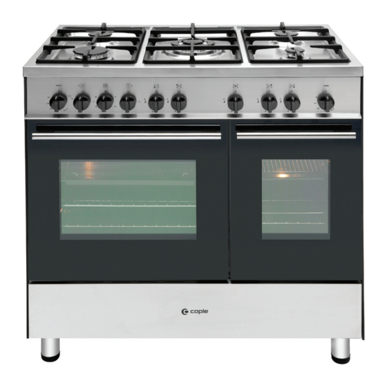
- Page 1 Instruction manual for range cooker Model code: CR 9218 Contact Caple on 0844 800 3830 or for spare parts www.4caple.co.uk...
- Page 2 Thank you for buying your new Caple cooker. To ensure that you get the best results from your new Caple cooker, we strongly suggest that you read this instruction manual thoroughly before use. This manual contains installation advice, cleaning tips and a cooking guide, as well as other important facts about your Caple cooker.
-
Page 3: Important Safety Precautions And Recommendations
Important safety precautions and recommendations IMPORTANT: This appliance is designed and manufactured solely for the cooking of domestic (household) food and is not suitable for any non domestic application and therefore should not be used in a commercial environment. The appliance guarantee will be void if the appliance is used within a non domestic environment i.e. a semi commercial, commercial or communal environment. - Page 4 • Do not use a steam cleaner because the moisture can get into the ap- pliance thus make it unsafe. • Do not touch the appliance with wet or damp hands (or feet). • Do not use the appliance whilst in bare feet. • If you should decide not to use this appliance any longer (or decide to substitute another model), before disposing of it, it is recommended that it be made inoperative in an appropriate manner in accordance to...
- Page 5 • WARNING: Danger of fire: do not store items on the cooking surfaces. • WARNING: When correctly installed, your product meets all safety requirements laid down for this type of product category. However spe- cial care should be taken around the rear or the underneath of the ap- pliance as these areas are not designed or intended to be touched and may contain sharp or rough edges, that may cause injury.
-
Page 6: Electrical Installation
1 - Electrical Installation For your safety please read the following information: This appliance must be installed by a qualified technician according with the current local regulations and in compliance with the manufacturer instructions. This appliance is supplied with a moulded 13 amp three pin mains plug with a 3 amp fuse fitted. - Page 7 Electrical feeder cable connection The operations must be executed by a qualified technician. To connect the supply cable: - Remove the screws securing the cover “A” on the rear of the cooker (fig. 1.2). - Unscrew cable clamp “D” (fig. 1.3). - Connect the wires to the terminal block “B”...
-
Page 8: For The Installer
FOR THE INSTALLER 2 - Location This cooker has class “2/1” overheating protection so that it can be installed next to a cabinet. The cooker must be installed by a qualified technician and in compliance with local safety standards. The appliance may be installed in a kitchen, kitchen/diner or a bed sitting room, but not in a room or space containing a bath or a shower. -
Page 9: Levelling The Cooker
Fitting the adjustable feet The adjustable feet must be fitted to the base of the cooker before use. Rest the rear of the cooker on a piece of the polystyrene packaging exposing the base for the fitting of the feet. Fit the 4 legs by screwing them tight into the support base as shown in picture 2.3. - Page 10 WARNING When raising cooker to upright posi- tion always ensure two people carry out this manoeuvre to prevent dam- age to the adjustable feet (fig. 2.5). WARNING Be carefull: do not lift the cooker by the door handle when raising to the upright position (fig. 2.6).
-
Page 11: Stability Bracket
Stability bracket We recommend a stability bracket is fitted to the cooker. The type shown in fig. 2.8 can be purchased from most plumbers merchants and do it yourself (D.I.Y.) shops. Existing slot in rear of cooker Bracket Dotted line showing the position Fig. -
Page 12: Provision For Ventilation
Provision for ventilation – The appliance should be installed into a room or space with an air supply in accordance with BS 5440-2: 2000. – For rooms with a volume of less than 5 m - permanent ventilation of 100 cm free area will be required. -
Page 13: Gas Installation
3 - Gas installation IMPORTANT NOTE This appliance is supplied for use on NATURAL GAS or LPG (check the gas regulation label attached on the appliance). – Appliances supplied for use on NATURAL GAS: they are adjusted for this gas only and cannot be used on any other gas (LPG) without modification. -
Page 14: Gas Connection
Gas connection The installation of the gas appliance to Natural Gas or LP Gas must be carried out by a suitably qualified and registered person. Installers shall take due account of the provisions of the relevant British Standards Code of Practice, the Gas Safety Regulations and the Building Standards (Scotland)(Consolidation) Regulations issued by the Scottish Development Department. - Page 15 Gas connection Cat: II 2H3+ The gas supply must use the nearest gas inlet pipe which is located at the left or the right hand side at the rear of the appliance (figs. 3.1, 3.3). The hose should also be connected in such away that it does not touch the floor. To screw the connecting tube operate with two spanners (fig.
- Page 16 Important prescriptions for gas connection Rear wall Suggested area for gas mains connection Fig. 3.3...
-
Page 17: Conversion To Natural Gas Or To Lpg
Conversion to Natural Gas or to LPG Injectors replacement of top Auxiliary, rapid and Semi-rapid burners burner Every cooker is provided with a set of injectors for the various types of gas. Injectors not supplied can be obtained from the After-Sales Service. Select the injectors to be replaced ac- cording to the table at page 18. -
Page 18: Lubrication Of The Gas Taps
TABLE FOR THE CHOICE OF THE INJECTORS G 20 G30 - 28-30 mbar Cat: II 2H 3+ G31 - 37 mbar 20 mbar Nominal Reduced Ø injector Ring opening Ø injector Ring opening Power Power BURNERS [1/100 mm] [mm] [1/100 mm] [mm] [Hs - kW] [Hs - kW]... - Page 19 Operations to be executed for the replacement of the injectors of the oven and grill burners Some models are provided with a set of injectors for the various types of gas. If the injectors are not supplied they can be obtained from the “Service Centre”. Select the injectors to be replaced according to the “Table for the choice of the injectors” (for the gas category check the data label attached on the appliance). The nozzle diameters, expressed in hundredths of a millimetre, are marked on the body of each injector.
- Page 20 Grill burner (Left oven only) • Unscrew and remove the burner securing screw “A” (fig. 3.9). • Withdraw the burner as shown in figure 3.9. Take care not to damage the safety valve probe and the electric ignition electrode. • Using a 7 mm box spanner, unscrew the injector (indicated by the arrow in fig. 3.10) and replace it with a new one selected in accordance with the “Table for the choice of the injectors”.
- Page 21 Regulation of air supply to oven and grill burner (Grill burner on left main oven only) To regulate the air supply it is necessary to remove the burners from their housings (figs. 3.8 - 3.10). Using a cross-head screwdriver, slacken the screws “A” securing the air flow regu- • lation collar “B” (fig. 3.11) and move the collar forward or backward to increase or reduce the air aperture in accordance with gas type and the indications in the “Table for the choice of the injectors”.
- Page 22 LEFT and RIGHT OVENS Regulating of the oven minimum This needs to be done only for the oven burner (the grill of the left oven is a fixed capacity) by acting on the thermostat. Considering that in the minimum posi- tion the flame must have a length of about 4 mm and must remain lit even with a brusque passage from the maxi- Fig.
-
Page 23: Features And Technical Data
4 - Features and Technical Data Fig. 4.1 Cooking hob - (Fig. 4.1) 1. Auxiliary burner (A) 1,00 kW 2. Semi-rapid burner (SR) 1,75 kW 3. Rapid burner (R) 3,00 kW 4. Triple-ring burner (TR) 3,50 kW Important Note: The electric ignition is incorporated in the knobs. The appliance has a safety valve system fitted, the flow of gas will be stopped if and when the flame should accidentally go out. -
Page 24: Control Panel
Control Panel Fig. 4.2 Control panel - Controls description (Fig. 4.2) 1. Left gas oven/gas grill control knob 2. Left oven light control knob 3. Minute counter 4. Right oven light control knob 5. Front left burner control knob 6. Rear left burner control knob 7. -
Page 25: How To Use The Hob Burners
How To Use the Hob Burners Hob burners Each hob burner is controlled by a sepa- rate gas tap operated by a control knob (fig. 4.3) which has 3 positions marked on the control panel, these are: – Symbol • : tap closed (burner off) –... - Page 26 Choice of burner The burner must be chosen according to the diameter of the pans and energy required. Fig. 4.4 Burners Pan diameter Auxiliary 12 ÷ 14 cm Semi-rapid 16 ÷ 24 cm Rapid 24 ÷ 26 cm Triple-ring 26 ÷ 28 cm do not use pans with concave or convex bases Saucepans with handles which are excessively heavy, in relationship to the weight of the pan, are safer as they are less likely to tip.
- Page 27 5 - Minure counter The minute counter is a timed acoustic warning device which can be set for a maximum of 60 minutes. The knob (fig. 5.1) must be rotated clockwise as far as the 60 minute posi- tion and then set to the required time by rotating it anticlockwise.
-
Page 28: General Features
6 - Left main gas oven Oven thermostat Attention: the oven door becomes The temperature knob is numbered from very hot during operation. (fig. 6.1) indicating the Keep children away. increasing oven temperature value (see table 6.2). General features The thermostat which regulates the flow of gas to the oven burner has a safety It is advisable, upon first use, to turn the valve which automatically shuts off the... - Page 29 Ignition of the oven burner 1) Open the oven door to the full extent. WARNING: Risk of explosion! The oven door must be open during this operation. 2) Lightly press and turn the temperature knob anti-clockwise (fig. 6.3) to the max position ( fig. 6.1). 3) Press the knob firmly until the burner lights.
-
Page 30: Oven Cooking
Oven cooking Oven light For efficient oven preheating, we rec- The cooker is equipped with a light that ommend that grill tray and shelf are illuminates the oven to enable visually removed from the oven and replaced controlling the food that is cooking. after about 15 minutes. - Page 31 Ignition of the grill burner IMPORTANT: the grill must always be used with the oven door ajar and with shield “A” mounted (fig. 6.8). Do not grill with the oven door closed. Attention: the oven door becomes very hot during operation. Keep children away.
-
Page 32: Use Of The Grill
Use of the grill Notes: – The grill burner has only one setting, Very important: the grill must always that is full-on. be used with the oven door slightly – It is important that the heat shield is open and with shield “A” mounted fitted the correct way up, as shown in (Fig. 6.8). -
Page 33: Right Small Gas Oven
7 - Right small gas oven Oven thermostat Attention: the oven door becomes The temperature knob is numbered from very hot during operation. (fig. 7.1) indicating the Keep children away. increasing oven temperature value (see table 7.2). General features The thermostat which regulates the flow of gas to the oven burner has a safety The oven is furnished completely clean;... - Page 34 Ignition of the oven burner 1) Open the oven door to the full extent. WARNING: Risk of explosion! The oven door must be open during this operation. 2) Lightly press and turn the temperature knob anti-clockwise (fig. 7.3) to the max position ( fig. 7.1). 3) Press the knob firmly until the burner lights.
- Page 35 Recommended cooking temperature Food °C °F Gas Shelf Cooking Mark Position Time (approx) CAKES Victoria sandwich 2 or 3 20-25 mins Small cakes/buns 1 and 2 15-20 mins Maidera cake 2 or 3 20 mins Fruit cake 1¾ hours Rich fruit cake 3 or 4 2½...
-
Page 36: Cleaning And Maintenance
8 - Cleaning and Maintenance General advice – When the appliance is not being used, it is advisable to keep the gas tap closed. – Every now and then check to make sure that the flexible tube that connects the gas line or the gas cylinder to the appliance is in perfect condition and eventually substitute it if it shows signs of wearing or damage. -
Page 37: Enamelled Parts
Enamelled parts All the enamelled parts must be cleaned with a sponge and soapy water or other non- abrasive products. Dry preferably with a microfibre or soft cloth. Acidic substances like lemon juice, tomato sauce, vinegar etc. can damage the enamel if left too long. - Page 38 Burners They can be removed and washed with soapy water only. They will remain always perfect if cleaned with products used for silverware. After cleaning or wash, check that burner-caps and burner-heads are dry before placing them in the respective housings. Note: To avoid damage to the electric ignition do not use it when the burners are not in place.
- Page 39 Triple ring burners The triple ring burner must be correctly positioned (see fig. 8.5); the burner rib must be enter in their logement as shown by the arrow see fig. 8.3). Then position the cap “A” and the ring “B” (fig. 8.4 - 8.5). The burner correctly positioned must not rotate (fig.
-
Page 40: Oven Doors
Fig. 8.6 Fig. 8.7 Oven doors Storage compartment The internal glass panel can be easily The storage compartment is accessible removed for cleaning by unscrewing the through the pivoting panel (fig. 8.7). retaining screws (Fig. 8.6) Do not store flammable material in Do not use harsh abrasive cleaners or the ovens or in the storage compart- sharp metal scrapers to clean the oven... - Page 41 Inside of ovens Assembly and dismantling of the side runner frames The oven should always be cleaned after use when it has cooled down. – Fit the side runner frames into the The cavity should be cleaned using a holes on the side walls inside the oven mild detergent solution and warm water. (fig.
-
Page 42: Removing The Oven Door
Removing the oven door The oven door can easily be removed as follows: – Open the door to the full extent (fig. 8.10a). – Open the lever “A” completely on the left and right hinges (fig. 8.10b). – Hold the door as shown in fig. 8.10. Fig. -
Page 43: Helpful Advice
If Your Oven Does Not Work shelves rather than towards the sides of tho oven. Before calling a Caple service engineer 3. Rotate the food a half turn in the oven. run through the following checklist. 4. Try pre-heating the oven for 5-15 min- utes prior to baking. -
Page 44: Your Guarantee
YOUR GUARANTEE Caple guarantees all parts of this product for one year from the date of pur- chase. During that time, should it become necessary Caple engineers will replace or repair all defective parts free of charge, except for parts subject to fair wear and tear, such as lightbulbs.
Need help?
Do you have a question about the CR 9218 and is the answer not in the manual?
Questions and answers