
Subscribe to Our Youtube Channel
Related Manuals for Integra DTA-70.1


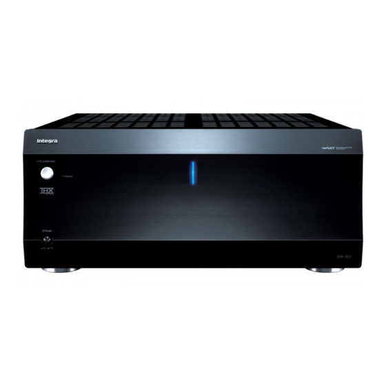
Summary of Contents for Integra DTA-70.1
- Page 1 DTA-70.1_En_100108.book Page 1 Friday, January 8, 2010 2:04 PM 9-Channel Amplifier DTA-70.1 Instruction Manual...
-
Page 2: Important Safety Instructions
DTA-70.1_En_100108.book Page 2 Friday, January 8, 2010 2:04 PM WARNING: TO REDUCE THE RISK OF FIRE OR ELECTRIC SHOCK, DO NOT EXPOSE THIS APPARATUS TO RAIN OR MOISTURE. CAUTION: TO REDUCE THE RISK OF ELECTRIC SHOCK, DO NOT REMOVE COVER (OR BACK). NO USER-SERVICEABLE PARTS INSIDE. -
Page 3: Precautions
DTA-70.1_En_100108.book Page 3 Friday, January 8, 2010 2:04 PM Precautions 1. Recording Copyright—Unless it’s for personal use only, recording copyrighted material is illegal with- out the permission of the copyright holder. 2. AC Fuse—The AC fuse inside the unit is not user- serviceable. -
Page 4: Features
DTA-70.1_En_100108.book Page 4 Friday, January 8, 2010 2:04 PM Thank you for purchasing an Integra 9-Channel Ampli- fier. Please read this manual thoroughly before making connections and plugging in the unit. Following the instructions in this manual will enable you to obtain optimum performance and listening enjoyment from your new 9-Channel Amplifier. -
Page 5: Table Of Contents
Appendix Troubleshooting... 18 Specifications ... 19 Supplied Accessories Check that the following accessories are supplied with the DTA-70.1. Power cord (Plug type varies from country to country.) Mono mini-plug cable (For connecting to the 12V trigger terminals.) Speaker cable labels... -
Page 6: Amplifier Precautions
DTA-70.1 to allow room for the cables and cords without excessively bend- ing them. Do not place the DTA-70.1 near TV or radio. This may cause noise or instable video on radio or TV respectively. Power cord Do not use a power cord other than the one supplied with the DTA-70.1. -
Page 7: Quick Operation Guide
Connections and operations are explained briefly here for the purpose of just getting you started. For those of you who want to operate the DTA-70.1 (the amplifier) right away, follow the guide below. However, this instruction manual contains a great deal of other... -
Page 8: Front & Rear Panels
DTA-70.1_En_100108.book Page 8 Friday, January 8, 2010 2:04 PM Front & Rear Panels Front Panel a Power switch This is the main power switch. When set to OFF, the amplifier is completely shutdown. It must be set to On to set the amplifier to On or Standby. b On/Standby button This button is used to set the amplifier to On or Standby. -
Page 9: Connections
Refer to the instruction manual supplied with the control amplifier and verify that its output terminal is compatible with the pin assignments for this ter- minal. The output terminal of Integra DTC-80.1 is compatible with the pin assignments for the termi- nal of the amplifier. - Page 10 DTA-70.1_En_100108.book Page 10 Friday, January 8, 2010 2:04 PM Front & Rear Panels—Continued b INPUT SELECT switch This switch is located between the balanced input and single-ended RCA input for each channel. Use this switch to select the input type for its channel. When setting the switch to the upper side, the bal- anced input is selected.
-
Page 11: Connecting The Amplifier
DTA-70.1_En_100108.book Page 11 Friday, January 8, 2010 2:04 PM Connecting the Amplifier Connecting Your Speakers Before connecting the speakers, place them correctly by consulting the instruction manuals that came with them. For surround playback, the configuration and placement of your speakers are very important. Please note that connecting speakers with a low power input rating does not produce large sound volumes. - Page 12 DTA-70.1_En_100108.book Page 12 Friday, January 8, 2010 2:04 PM Connecting the Amplifier—Continued Connecting the Speaker Cables Strip about 1/2" to 5/8" (12 to 15 mm) of insu- lation from the ends of the speaker cables, and twist the bare wires tightly, as shown.
-
Page 13: Connecting To An Av Controller With Xlr Output
Connecting to an AV Controller with XLR output Since many users will purchase the amplifier together with the Integra AV controller DHC-80.1, here is an explanation of how to connect the amplifier to the DHC-80.1. For more details, see the instruction manual of the connected compo- nent. -
Page 14: Connecting To An Av Controller With Rca Output
Connecting to an AV Controller with RCA output Since many users will purchase the amplifier together with the Integra AV controller DHC-80.1, here is an explanation of how to connect the amplifier to the DHC-80.1. For more details, see the instruction manual of the connected compo- nent. -
Page 15: Bi-Amping The Front Speakers
DTA-70.1_En_100108.book Page 15 Friday, January 8, 2010 2:04 PM Connecting the Amplifier—Continued Bi-amping the Front Speakers The FRONT L/R and SURR BACK L/R outputs can be used with front speakers and surround back speakers respec- tively, or bi-amped to provide separate tweeter and woofer feeds for a pair of front speakers that support bi-amping, providing improved bass and treble performance. -
Page 16: Multiroom Connections
DTA-70.1_En_100108.book Page 16 Friday, January 8, 2010 2:04 PM Connecting the Amplifier—Continued Multiroom Connections You can use three speaker systems with this amplifier—a surround-sound speaker system in your main listening room, Zone 2: a stereo speaker system in a second room, Zone 3: a stereo speaker system in a third room. The following examples are based on using the amplifier with the AV controller, DHC-80.1. - Page 17 DTA-70.1_En_100108.book Page 17 Friday, January 8, 2010 2:04 PM Connecting the Amplifier—Continued ■ Connection 2 Main room: You can enjoy up to 7-channel surround-sound playback. Zone 2: You can enjoy 2-channel stereo playback and video playback. Make either connection. Zone 2 AV controller Front right Front left...
-
Page 18: Troubleshooting
DTA-70.1_En_100108.book Page 18 Friday, January 8, 2010 2:04 PM Troubleshooting If the DTA-70.1 fails to function normally, first check the following points before contacting the dealer from whom you purchased this unit. If the problem is not solved after going through the following list, unplug the power cord and contact the dealer from whom you pur- chased this unit. -
Page 19: Specifications
DTA-70.1_En_100108.book Page 19 Friday, January 8, 2010 2:04 PM Specifications Amplifier section Rated Output Power All channels: North American: 150 watts minimum continuous power per channel, 8 ohm loads, 2 channels driven from 20 Hz to 20 kHz, with a maximum total harmonic distortion of 0.05% (FTC) 175 watts minimum continuous power per channel, 8 ohm loads,... - Page 20 DTA-70.1_En_100108.book Page 20 Friday, January 8, 2010 2:04 PM Integra Division of ONKYO U.S.A. CORPORATION 18 park Way, Upper Saddle River, N.J. 07458, U.S.A. Tel: 800-225-1946, 201-818-9200 Fax: 201-785-2650 http://www.integrahometheater.com Integra Division of ONKYO CORPORATION Y1001-1 Sales & Product Planning Div.: 2-1, Nisshin-cho, Neyagawa-shi, OSAKA 572-8540, JAPAN...
Need help?
Do you have a question about the DTA-70.1 and is the answer not in the manual?
Questions and answers