Table of Contents
Advertisement
Quick Links
Advertisement
Chapters
Table of Contents

Related Manuals for NAD T 562


Summary of Contents for NAD T 562
- Page 1 DRAFT DATE: 30 OCT, 2002 T 562 DVD / VCD / CD PLAYER...
-
Page 2: Table Of Contents
SECTION 1 SUMMARY CONTENTS PRODUCT SAFETY SERVICING GUIDELINES FOR VIDEO PRODUCTS … … … … … 1-4 SERVICING PRECAUTIONS … … … … … … … … … … … … … … … … … … … … … … … … … 1 - 5 *General Servicing Precautions *Insulation Checking Procedure *Electrostatically Sensitive Devices... -
Page 3: Product Safety Servicing Guidelines For Video Products
PRPDUCT SAFETY SERVICING GUIDELINES FOR VIDEO PRODUCTS CAUTION: DO NOT ATTEMPT TO MODIFY THIS PRODUCT IN CORRESPONDS TO 0.5 MILLIAMP A.C. ANY VALUE EXCEEDING THIS ANYWAY. NEVER PERFORM CUSTOMINIZED INSTALLATIONS LIMIT CONSTITUTED A POTENTIAL SHOCK HAZARD AND MUST BE WITHOUT MANUFACTURER ’... -
Page 4: Servicing Precautions
SERVICING PRECAUTIONS CAUTION: Electrostatically Sensitive (ES) Devices Before servicing the DVD player covered by this service data and its supplements and addends, read and follow Some semiconductor (solid state) devices can be damaged the SAFETY PRECAUTIONS. NOTE: if unforeseen easily by static electricity. Such components commonly are circumstances create conflict between the following called Electrostatically Sensitive (ES) Devices. -
Page 5: Specifications
SPECIFICATIONS DVD VIDEO PLAYER POWER SUPPLY……………………………………………… AC 230V,50Hz (EUR)/120V,60Hz(US/CANADA) Power consumption…………………………………………. 30W External dimensions ………………………………………… 435×80×280mm Weight (net) …………………………………………………… 4.6kg Signal system…………………………………………………. PAL (EUR)/NTSC (USA/CANADA) Laser ……………………………………………………………. Semiconductor laser, wavelength 650nm Frequency range(digital audio) …………………………….. 2Hz to 22kHz Signal-to-noise………………………………………………… More than 102dB(A-WEIGHTED) Audio dynamic ……………………………………………….. -
Page 6: Location Of Customer Controls
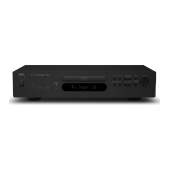
LOCATION OF CUSTOMER CONTROLS FRONT PANEL PAUSE Button Progressive Scan LED Disc Tray PLAY Button SKIP Button MENU Button DVD / CD / MP 3 Player T 562 PLAY PAUSE MENU SELECT PROGRESSIVE OPEN/CLOSE STOP SCAN OPEN/CLOSE Button SELECT Button... - Page 7 DISPLAY WINDOW MP3 Indicator ANGLE Indicator PROGRAM Indicator VCD Indicator PBC Indicator TITLE Indicator DTS Indicator DVD Indicator DIGITAL Indicator CHARTER Indicator PLAY Indicator REPEAT All Indicator L&R CHNNEL Indicator PAUSE Indicator REPEAT TRACK Indicator REMOTE CONTROL 1.POWER ON Button 2.POWER OFF Button 3.SUBTITLE Button 4.AUDIO Button...
- Page 8 EXPLODED VIEW T562 REF. NO. PART NO. DESCRIPTION Qty. F 001 67-009001-0 F ascia (C V ersion) 67-009002-0 F ascia (AH V ersion) P ower B utton F 002 77-009003-0 P ower B utton B ezel 77-001007-0 F 003 E nd C ap 66-009007-0 F 004 F 005...
- Page 9 IM 2(Spa. Starts) 90-009001-1 Manual Polybag 88-009001-0 Carton Box C Version 88-009002-0 Carton Box AH Version Proprietary information for servicing purposes only. The information herein may not be used commercially without the prior written agreement of NAD International, Toronto, Canada.
- Page 10 SECTION 2 ELECTRICAL CONTENTS CONTENTS ELECTRICL TROUBLESHOOTING GUIDE 1. SYSTEM CHECK … … … … … … … … … … … … … … … … … … … … … … … … … … … … … … … … 2-12 2.
-
Page 11: Electrical Troubleshooting Guide
ELECTRICAL TROUBLESHOOTING GUIDE 1. SYSTEM CHECK Power ON Power led green? Power led red? Check power board Check ext. trig part Does logo appear? Is J414 voltage normal? Check power board Check video part Is J409.CN7200, J16. CN7100 Disc reading? Reconnect Connected normal? Is J409 voltage normal? -
Page 12: Power Circuit
POWER CIRCUIT Input voltage 230V (C.Ver.) START Is F402 normally? Is voltage T403,D401 230V? A primary side abnormal Are D401, D409 normal? Is voltage J410 Are D409 T403 pin1 5V? Q405 normal? Replace defective parts Are U401,V401 normal? Check R420,C441, Is U401 pin6 U401. -
Page 13: Decode Circuit
3. DECODE CIRCUIT POWER ON Does NAD logo appear on screen? Does OSD appear normally? Check Video part Check U5 Does the Moving picture of the DVD Disc play on the Check U5, U22 screen normal? Does Check U5,U1,J2 and audio part... - Page 14 4. FRONT CIRCUIT START Is power led normally? Is U302 normal? Replace Check D311 Is display normal? Check U302 U301 Do all Does buttons Work normal? TACT switch normal? Replace TACT switch Check U302 Does remote Control work normally? Check U301 PROGRESSIVE SCAN Check D313, D314 l e d and HDCD l e d work...
-
Page 15: Etc
5. ETC A. Audio abnormal B. Video abnormal AUDIO ABNORMAL VIDEO ABNORMAL Check Audio Jack. Check Video Jack. Check the Mute TR. Refer to Video part. Refer to Audio part. Refer to decode. Refer to decode board. Replace B/D. Replace B/D. C. -
Page 16: Ic Block Diagrams & Signal Description
IC BLOCK DIAGRAMS & SIGNAL DESCRIPTION 1. U5 (V8601VWA DVD DSP) SIGNAL DESCRIPTION Signal Pins Description Front End DSYNC DVD parallel mode Sector Sync DREQ DVD parallel mode Data Request DCLK Data sampling clock DSTB Parallel mode Data Valid, serial mode Left/Right Clock DVD[7:0] DVD drive parallel data port, pins: 217, 219-223, 225, 226 External I/O... - Page 17 Signal Type Pins Description Comm Ports UART1 RXD1 UART1 serial data input from external serial device, used for IR receive / can be used as GPIO SSP1 SSPCLK1/CTS1- SSP1 clock or UART1 Clear to Send signal / can be used as GPIO SSPOUT1/DTR1- SSP1 data out or UART1 Data Terminal Ready signal / can be used as GPIO SSPIN1/BAUD1...
- Page 18 Signal Type Pins Description Video Port VIO[7:0] 126-131 Bidirectional digital video port data bus / can be used as GPIO 133-134 HSYNC Bidirectional HSYNC signal for devices that do not use EAV/SAV codes / can be used as GPIO VSYNC Bidirectional VSYNC signal for devices that do not use EAV/SAV codes / can be used as GPIO VIOCLK VCLK input/output for Video I/O Port function...
-
Page 19: Block Diagram
BLOCK DIAGRAM PIN CONNECTIONS DDIO MD10 MD11 SSIO MD12 SSIO MD13 MD14 MD15 DDIO DQM1 PWE1- DDIO SSIO AD10 AD11 AD12 AD13 DDIO SSIO SCLK MCLK AD14 SSIO AD15 PWE2- AD16 DDIO DDIO AD17 NDV8601 MA10 AD18 MA11 AD19 AD20 SSIO MA12 AD21... - Page 20 BLOCK DIAGRAM DIGITAL +3.3V REAR PANEL DIGITAL +5V ANALOG +12V ANALOG -12V SDRAM FLASH FLASH POWER SUPPLY OPITICAL OUT V-20V ANALOG +5V W986432 AM29LV800BB-90EC DIGITAL AUDIO STANDBY +5V COAXIAL OUT 12V TRG CONTROL EEPROM 93C46 DVD FRONT END AUDIO DOWN MIX DAC DECODE PCB NDV8601VWA XWM8716...
-
Page 21: Wiring Diagram
WIRING DIAGRAM J412 J410 J503 J413 J502 J405 J613 J608 J612 J414 CN7200 J409 FP7100 J406 J411 J301 J303 J304... - Page 22 PSU V2.0 AC IN J406 POWER SWITCH TO FPP R403 D402 8R2/0.5W FR104 C433 TO J413 222/400V C405 -20V 100U/10V R405 R404 TO J405 D408 R402 J412 J413 D403 6.8V 33R/0.5W FR104 R406 C406 L405 47U/50V C434 2*16mH Q407 J409 FB403 D406 R413...
- Page 23 MECHANISM AND MEMORY DIAGRAM FLASHCS0- PWE0- DQM3- V3.3 V3.3 DQM2- RSTP- FLASHVCC DQM1- DQM0- HIGH MD23 MD31 LA16 DQ24 DQ23 CAS- VSSQ VCCQ MD22 MD30 LA15 RAS- DQ25 DQ22 LA[3:0] MD21 MD29 LA14 CS1- DQ26 DQ21 LA13 CS0- VCCQ VSSQ MD20 MD28 LA12...
- Page 24 KEYBOARD AND DISPLAY J301 FROM PSU -20V C301 C303 C302 10UF/16V 10UF/50V 0.1uF/50V U301 20U39119BAN GRID4 SEG8 GRID3 SEG7 GRID2 SEG6/KS6 GRID1 SEG5/KS5 SEG4/KS4 LED4 SEG3/KS3 D305 D301 D302 D303 D304 LED3 SEG2/KS2 UPD16312 IN4148 IN4148 R317 LED2 SEG1/KS1 IN4148 IN4148 IN4148 D311...
- Page 25 PANTERA V2.0 VIDEO SIGNALS RXD0 TXD0 RSTP- SSPIN0 16BY9 16BY9R TO DVD FE BUFFOEN SCARTINT SCARTINTR V5.0 To FLASH SRST- STANDBY STANDBYR SRST- VIDEO output SPAREINT SPAREINTR LM809P3 0.1UF SSPOUT0B 20PF TOP VIEW 100K CVBS SSPCLK1XR SSPCLK0B 16BY9 0.1UF LP3965EMP-18 150R SSPOUT1XR SSPCLK1BF...
- Page 26 VIDEO DIAGRAM R604 330R J606 TOP VIEW Q603 FB602 SCART-AOR SAORC UN2216CT U605 C678 +5V-VID 680P SAOLC R603 FB603 VOUT VOUT2 330R C607 gnda SCART-AOL AGND C638 C609 10UF 10V Q604 0.1UF 10UF 10V UN2216CT C679 C643 BGND LM1117MP-5.0 680P MUTECTRL 0.1UF C677...
- Page 27 AUDIO DIAGRAM LRCLK DMDACCS- LRCIN ML/I2S AOUT3 SSPCLK1 MC/DM1 ACLK SSPOUT1 BCKIN MD/DM0 C701 CLKO MUTE PCMCLK 220PF MODE CS/IWO gnda L601 SRST- C698 gnda DGND 10UH ZERO 390PF R689 R685 LEFT VCC2 Q605 J611 VCC2R VCC2L C616 C662 10K 1% AUDIO DOWNMIX 3.83K 1% UN2216CT...
- Page 28 ADDENDUM 8 PIN SCART MODIFICATON SCART PIN8 from r699 wire A1015 wire +12V IN4148 C1815 from R615 wire 16:9 H from R703 wire from SCART H wire C1815...
- Page 30 © NAD 2002 NAD ELECTRONICS INTERNATIONAL CANADA...
Need help?
Do you have a question about the T 562 and is the answer not in the manual?
Questions and answers