Table of Contents
Advertisement
Advertisement
Table of Contents

Subscribe to Our Youtube Channel
Related Manuals for Toa FS-7006PA


Summary of Contents for Toa FS-7006PA
-
Page 1: Power Amplifiers
OPERATING INSTRUCTIONS POWER AMPLIFIERS FS-7006PA FS-7012PA AMPLIFIER AUTO SWITCHING YA-7000 MODULE (Optional) Thank you for purchasing TOA's Power Amplifiers. Please carefully follow the instructions in this manual to ensure long, trouble-free use of your equipment. -
Page 2: Table Of Contents
8. FAILURE INDICATION ..................16 9. DIMENSIONAL DIAGRAM ................17 10. BLOCK DIAGRAMS 10.1. FS-7006PA ..................... 18 10.2. FS-7012PA ..................... 19 10.3. YA-7000 ......................20 11. SPECIFICATIONS 11.1. FS-7006PA/7012PA Power Amplifiers ............21 11.2. YA-7000 Amplifier Auto Switching Module (Optional) ........22... -
Page 3: Safety Precautions
AC outlet and • Be sure to replace the unit's terminal cover after contact your nearest TOA dealer. Make no further connection completion. Because the voltage of up attempt to operate the unit in this condition as this to 100 V is applied to the high impedance speaker may cause fire or electric shock. - Page 4 • When unplugging the power supply cord, be sure • Contact your TOA dealer as to the cleaning. If dust to grasp the power supply plug; never pull on the is allowed to accumulate in the unit over a long cord itself.
-
Page 5: General Description
2. GENERAL DESCRIPTION TOA's FS-7006PA (600 W) and FS-7012PA (1,200 W) are power amplifiers designed for 100 V line and high impedance applications. By mounting an optional YA-7000 module in the power amplifier and connecting it to a standby amplifier, the power amplifier can be automatically switched over to the standby amplifier if the power amplifier fails, allowing broadcasts in progress to continue uninterrupted. -
Page 6: Installation Precautions
• Because the amplifier is heavy (24.8 kg for FS-7006PA, 35.4 kg for FS-7012PA), be sure to reinforce the fittings used to fix the amplifier in place when mounting in a rack and requiring extra strenght. -
Page 7: Nomenclature And Functions
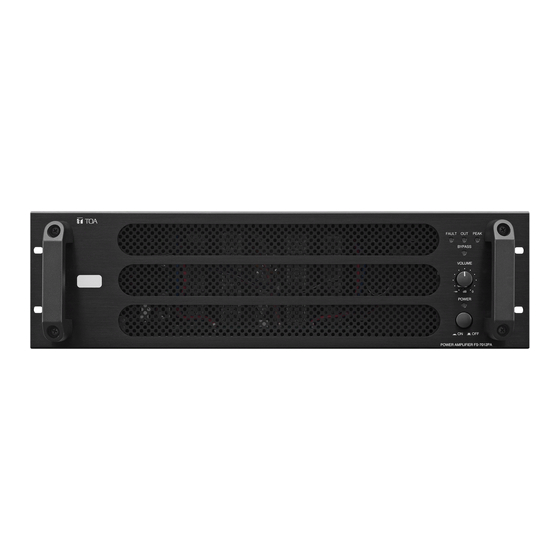
6. NOMENCLATURE AND FUNCTIONS 6.1. FS-7006PA/7012PA Power Amplifiers [Front] Figure shows the FS-7012PA. 1. Power Switch 6. Signal Indicator Press this switch to turn on the power. To turn off Lights when a signal that exceeds a level 24 dB the power, press this switch again. -
Page 8: Rear
• FS-7012PA M4 screw terminal; barrier distance: 9 mm; load impedance: 8.3 Ω Note Never connect this terminal to the speaker output terminal of other FS-7006PA or FS-7012PA power amplifier. Failure to follow this instruction could lead to equipment failures. -
Page 9: Ya-7000 Amplifier Auto Switching Module (Optional)
Note Standby Amplifier Input (3) are output if a main Only 1 piece of the FS-7006PA or FS-7012PA can amplifier failure is detected. be connected to this terminal. Never connect 2 or (M4 screw terminal; barrier distance: 9 mm) more units to this terminal, as the excessive load could cause the amplifier to fail. -
Page 10: Connections
The TERMINALS marked with the symbol are HAZARDOUS LIVE. The external wiring to these terminals requires installation by an INSTRUCTED PERSON. Composite impedance 100 V line 16.7Ω (FS-7006PA) 8.3Ω (FS-7012PA) FS-7006PA/7012PA Speaker Output Terminal 7.2. Volume Control Bypass Control Input Connections Announcements requiring particular urgency (such as emergency broadcasts) can override the normal volume control on the front of the amplifier in order to be heard at maximum sound volume. -
Page 11: Mounting And Connecting The Ya-7000
7.3. Mounting and Connecting the YA-7000 7.3.1. YA-7000 Installation Step 1. Use nippers or a similar tool to remove the amplifier's rear-mounted YA-7000 receptacle panel by cutting away the portions marked with (6 places). Figure shows the FS-7012PA. Step 2. Connect the YA-7000's harness to the amplifier's internal connector. -
Page 12: Ya-7000 Connections
• Standby amplifiers cannot be shared with other main amplifiers. • Only 1 piece of FS-7006PA or FS-7012PA can be connected to the YA-7000's main amplifier input and standby amplifier input. Never connect 2 or more amplifiers to each of these terminals, as the excessive load could cause the amplifier to fail. - Page 13 [Wiring Diagram] 100 V line Composite impedance 16.7Ω (FS-7006PA) Speaker Output Terminal 8.3Ω (FS-7012PA) Main Amplifier YA-7000 Input Terminal [Main Amplifier] Standby Amplifier Input Terminal Speaker Output Terminal Audio Signal Input Terminal [Standby Amplifier] Speaker Output Terminal Audio Signal Input Terminal...
-
Page 14: Checking Amplifier Operation
7.3.3. Checking Amplifier Operation Step 1. Shift the YA-7000's Operation mode selector switch to the "TEST" position while making a broadcast. Confirm that even with the switch in this Test position, the broadcast continues and the main amplifier's Fault indicator lights. Fault Indicator (lights) NORMAL... -
Page 15: Removable Terminal Plug Connection
7.4. Removable Terminal Plug Connection Cautions • Avoid soldering cable conductor, as contact resistance may increase when the cable is tightened and the solder is crushed, possibly resulting in an excessive rise in joint temperatures. • Use cables of AWG 12 – 24. Cable end treatment 2-core shielded cable 7 mm... -
Page 16: Failure Indication
Contact your TOA dealer to arrange for diagnosis and repair. The following causes can be considered when the Fault indicator lights:... -
Page 17: Dimensional Diagram
9. DIMENSIONAL DIAGRAM Unit: mm The FS-7006PA's external dimensions are identical to those of the FS-7012PA. 532.7 441.2... -
Page 18: Block Diagrams
10. BLOCK DIAGRAMS 10.1. FS-7006PA... -
Page 19: Fs-7012Pa
10.2. FS-7012PA... -
Page 20: Ya-7000
10.3. YA-7000 TO FS-7012PA/FS-7006PA SPEAKER OUTPUT POWER FAULT IN FAULT OUT MAIN AMP INPUT PILOT TONE IN PILOT TONE PILOT TONE STANDBY AMP INPUT OSCILLATOR DETECTOR... -
Page 21: Specifications
11. SPECIFICATIONS 11.1. FS-7006PA/7012PA Power Amplifiers Model No. FS-7006PA FS-7012PA Power Source 230 V AC, 50 Hz Power Consumption 1,090 W (1,540 VA) (at rated output), 2,130 W (2,670 VA) (at rated output), 390 W (600 VA) (IEC 65), 750 W (950 VA) (IEC 65),... -
Page 22: Ya-7000 Amplifier Auto Switching Module (Optional)
11.2. YA-7000 Amplifier Auto Switching Module (Optional) Power Source 24 V DC (supplied from the power amplifier) Current Consumption 70 mA Input Main amplifier input: Connects to the main amplifier's output (100 V line), M4 screw terminal, distance between barriers: 9 mm Standby amplifier input: Connects to the standby amplifier's output (100 V line), M4 screw terminal, distance between barriers: 9 mm Output... - Page 24 133-22-066-70...
Need help?
Do you have a question about the FS-7006PA and is the answer not in the manual?
Questions and answers