
Subscribe to Our Youtube Channel
Related Manuals for Toa A-1706


Summary of Contents for Toa A-1706
-
Page 1: Operating Instructions
OPERATING INSTRUCTIONS PA AMPLIFIER A-1706 A-1712 A-1724 Please follow the instructions in this manual to obtain the optimum results from this unit. We also recommend that you keep this manual handy for future reference. -
Page 2: Table Of Contents
TABLE OF CONTENTS 1. SAFETY PRECAUTIONS ................3 2. GENERAL DESCRIPTION ................4 3. FEATURES ......................4 4. NOMENCLATURE AND FUNCTIONS Front ......................... 5 Rear .......................... 5 5. CONNECTIONS 5.1. Speaker Connections ..................7 5.2. Remote Volume Control Connection ..............7 5.3. -
Page 3: Safety Precautions
When Installing the Unit the power supply plug from the AC outlet and contact your nearest TOA dealer. Make no further • Do not expose the unit to rain or an environment attempt to operate the unit in this condition as this where it may be splashed by water or other liquids, may cause fire or electric shock. -
Page 4: General Description
2. GENERAL DESCRIPTION Equipped with 6 Microphone inputs and 5 AUX inputs (simultaneous use of 9 inputs possible), TOA's A-1706, A-1712, and A-1724 PA Amplifiers are designed to suit PA system applications such as announcements, BGM and broadcasting in mosques, churches, large rooms and factories. -
Page 5: Nomenclature And Functions Front
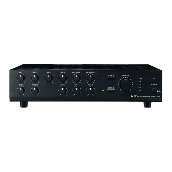
4. NOMENCLATURE AND FUNCTIONS [Front] This figure represents the A-1724. [Rear] This figure represents the A-1724. 1. Power switch 6. Bass control Press to turn ON the power. Adjusts bass response. Rotate clockwise to Press again to turn the power OFF. increase bass output, and counterclockwise to reduce it. - Page 6 9. Zone selector switches 19. AUX input terminals [AUX 3, 4] Select the desired broadcast zone. –20 dB, 10 kΩ, unbalanced. Monaural RCA pin Pressing the ZONE 1 and 2 switches allows the jacks. Accept external equipment output signals. ZONE 1 and 2 output terminals (14) to output signals, respectively.
-
Page 7: Connections
100 V 100 V 4 16Ω 100 V 100 V 100 V Total impedance 167 Ω (A-1706) 83 Ω (A-1712) 42 Ω (A-1724) 4 – 16 Ω 100 V line 100 V line Notes • Both the 4 – 16 Ω and 100 V terminals cannot be used at the same time. -
Page 8: External Equipment Connection To The Line Out And Pwr Amp In Terminals
5.4. External Equipment Connection to the LINE OUT and PWR AMP IN Terminals By connecting a signal processor such as an A-1700 series equalizer or limiter between the preamplifier section (LINE OUT) and the power amplifier section (PWR AMP IN) of the A-1700 series, signals can be tailored for desired sound output. -
Page 9: Rack Mounting
9. RACK MOUNTING To mount the unit in a standard 19" equipment rack, use the optional MB-25B Rack Mounting Bracket. Attach the MB-25B to the unit using the supplied 4 screws. When using other screws, each screw must be shorter than 16 mm. M4 x 16 Machine screw included in MB-25B Amplifiers MB-25B... -
Page 10: Block Diagram
11. BLOCK DIAGRAM... -
Page 11: Specifications
13.5 kg 0 dB = 1 V 167 Ω (A-1706), 83 Ω (A-1712), 42 Ω (A-1724) Distance between barriers on the above screw terminals: 7 mm (M3 screw), 9 mm (M4 screw) Note: The design and specifications are subject to change without notice for improvement. -
Page 12: Dimensional Diagram
13. DIMENSIONAL DIAGRAM (Applicable to all models) Unit: mm 18.5 326.5 Traceability Information for Europe (EMC directive 2004/108/EC) Manufacturer: Authorized representative: TOA Corporation TOA Electronics Europe GmbH 7-2-1, Minatojima Nakamachi, Chuo-ku, Kobe, Hyogo, Suederstrasse 282, 20537 Hamburg, Japan Germany URL: http://www.toa.jp/ 133-12-845-5C...
Need help?
Do you have a question about the A-1706 and is the answer not in the manual?
Questions and answers