Table of Contents
Advertisement
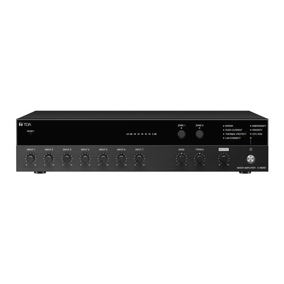
MIXER AMPLIFIER
A-3606D, A-3612D, A-3624D, A-3648D
About Firmware Upgrade
The latest firmware is available on the TOA DATA Library (https://www.toa-products.com/international/).
Perform a search for the product number "A-3606D, A-3612D, A-3624D, or A-3648D" and download
the latest firmware.
Thank you for purchasing TOA's Mixer amplifier.
Please carefully follow the instructions in this manual to ensure long, trouble-free use of your equipment.
OPERATING INSTRUCTIONS
The figure represents the A-3648D.
Advertisement
Table of Contents


Need help?
Do you have a question about the A-3606D and is the answer not in the manual?
Questions and answers