Table of Contents
Advertisement
EMERGENCY PUBLIC
ADDRESS SYSTEM
Thank you for purchasing TOA's EMERGENCY PUBLIC ADDRESS SYSTEM.
Please carefully follow the instructions in this manual to ensure long, trouble-free use of your equipment.
MONITOR VOLUME
MONITOR VOLUME
5
4
6
3
7
-24dB
-18dB
-12dB
-6dB
-3dB
0dB
2
8
9
1
OFF
10
MIN
MAX
MONITOR PANEL MP-210-AS
BUZZER CTRL
AMP1
AMP2
AMP3
AMP4
AMP5
AMP6
STANDBY
POWER
ON
FAULT
OFF
CHANGEOVER
AMPLIFIER CHANGEOVER PANEL FV-200CA-AS
DC
AC
DC POWER SUPPLY PANEL FV-200PS-AS
INSTRUCTION MANUAL
FV-200 SERIES
Advertisement
Table of Contents

Subscribe to Our Youtube Channel
Related Manuals for Toa FV-200 Series


Summary of Contents for Toa FV-200 Series
- Page 1 AMP5 AMP6 STANDBY POWER FAULT CHANGEOVER AMPLIFIER CHANGEOVER PANEL FV-200CA-AS DC POWER SUPPLY PANEL FV-200PS-AS Thank you for purchasing TOA's EMERGENCY PUBLIC ADDRESS SYSTEM. Please carefully follow the instructions in this manual to ensure long, trouble-free use of your equipment.
- Page 1 -12dB -6dB -3dB MONITOR PANEL MP-210-AS AMPLIFIER CHANGEOVER PANEL FV-200CA-AS DC POWER SUPPLY PANEL FV-200PS-AS Thank you for purchasing TOA's EMERGENCY PUBLIC ADDRESS SYSTEM. Please carefully follow the instructions in this manual to ensure long, trouble-free use of your equipment.
-
Page 2: Table Of Contents
TABLE OF CONTENTS 1. SAFETY PRECAUTIONS ........................2. SYSTEM SUMMARY ......................... 3. FEATURES ............................4. INSTALLATION PRECAUTIONS ......................5. NOMENCLATURE AND FUNCTIONS ....................5.1. FV-200EV-AS Emergency Message Panel ................5.2. FV-200PP-AS Pre-Amplifier Mixer Panel ................... 5.3. FV-200RF-AS Microphone Receiver Panel ................5.4. -
Page 2: Table Of Contents
TABLE OF CONTENTS 1. SAFETY PRECAUTIONS ........................2. SYSTEM SUMMARY ......................... 3. FEATURES ............................4. INSTALLATION PRECAUTIONS ......................5. NOMENCLATURE AND FUNCTIONS ....................5.1. FV-200EV-AS Emergency Message Panel ................5.2. FV-200PP-AS Pre-Amplifier Mixer Panel ................... 5.3. FV-200RF-AS Microphone Receiver Panel ................5.4. - Page 3 7.17.3 . Wiring Diagram Connection to UPS ................7.17.4. Wiring Diagram Connection to VX-2000DS ..............8. SETTINGS ............................FV-200RF-AS Settings 8.1........................ 8.1.1. DIP Switch Functions ......................8.1.2. Priority Setting : Last-in-first-out / First-in-first-out / Individual priority ......8.1.3. RM-200M Unit Number Setting ..................8.2.
- Page 3 7.17.3 . Wiring Diagram Connection to UPS ................7.17.4. Wiring Diagram Connection to VX-2000DS ..............8. SETTINGS ............................8.1. FV-200RF-AS Settings ....................... 8.1.1. DIP Switch Functions ......................8.1.2. Priority Setting : Last-in-first-out / First-in-first-out / Individual priority ......8.1.3. RM-200M Unit Number Setting ..................8.2.
-
Page 4: Safety Precautions
1. SAFETY PRECAUTIONS Before installation or use, be sure to carefully read all the instructions in this section for correct and safe operation. Be sure to follow all the precautionary instructions in this section, which contain important warnings and/or cautions regarding safety. After reading, keep this manual handy for future reference. -
Page 4: Safety Precautions
1. SAFETY PRECAUTIONS Before installation or use, be sure to carefully read all the instructions in this section for correct and safe operation. Be sure to follow all the precautionary instructions in this section, which contain important warnings and/or cautions regarding safety. After reading, keep this manual handy for future reference. - Page 5 FV-200PS-AS / FV-224PA-AS / FV-248PA-AS / WARNING FV-248PA-AS 4 F00 When installing the unit All units All units CAUTION FV-200PS-AS / FV-224PA-AS / FV-248PA-AS / When the unit is in use FV-248PA-AS 4 F00 Only FV-224PA-AS / FV-248PA-AS / FV-248PA-AS 4 F00 Only Do not operate the unit for an extended period of time with the sound distorting.
- Page 5 FV-200PS-AS / FV-224PA-AS / FV-248PA-AS Only WARNING When installing the unit All units All units CAUTION FV-200PS-AS / FV-224PA-AS / FV-248PA-AS Only When the unit is in use FV-224PA-AS / FV-248PA-AS Only Do not operate the unit for an extended period of time with the sound distorting.
-
Page 6: System Summary
2. SYSTEM SUMMARY... -
Page 6: System Summary
2. SYSTEM SUMMARY... -
Page 7: Features
3. FEATURES 4. INSTALLATION PRECAUTIONS The required power volatge for this system is 220~ 230V AC. Calculate the total combined power consumption of all equipment in the system to ensure sufficient power capacity. Note that the system may not work properly due to breaker cutoff or power voltage drops when the total supply voltage is insufficient. -
Page 7: Features
3. FEATURES 4. INSTALLATION PRECAUTIONS FV-200PS-AS FV-200PS-AS FV-200PS-AS FV-200PS-AS (FV-200PS-AS) -
Page 8: Nomenclature And Functions
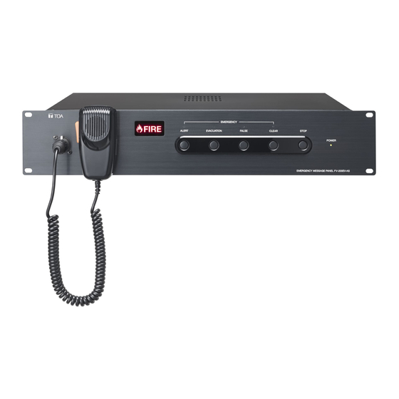
5. NOMENCLATURE AND FUNCTIONS 5.1. FV-200EV-AS Emergency Message Panel The FV-200EV-AS is an emergency broadcast operation panel for FV-200 Series Emergency Public Address Systems. This panel is not required if the system is to be used solely for general-purpose public address applications. -
Page 8: Nomenclature And Functions
5. NOMENCLATURE AND FUNCTIONS 5.1 FV-200EV-AS Emergency Message Panel The FV-200EV-AS is an emergency broadcast operation panel for FV-200 Series Emergency Public Address Systems. This panel is not required if the system is to be used solely for general-purpose public address applications. - Page 9 [Rear] EMERGENCY MESSAGE PANEL FV-200EV-AS TOA Corporation , JAPAN MADE IN INDONESIA FA INPUT CONTROL OUTPUT MICROPHONE DC IN 24V, 250mA EV OUTPUT GROUND FV-200PS-AS 20. EV Output Terminal Connect the FV-200PP-AS to this terminal. 22. Functional Earth Terminal Connect this terminal to the...
- Page 9 [Rear] EMERGENCY MESSAGE PANEL FV-200EV-AS TOA Corporation , JAPAN MADE IN INDONESIA FA INPUT CONTROL OUTPUT MICROPHONE DC IN 24V, 250mA EV OUTPUT GROUND FV-200PS-AS 20. EV Output Terminal Connect the FV-200PP-AS to this terminal. 22. Functional Earth Terminal Connect this terminal to the...
-
Page 10: Fv-200Pp-As Pre-Amplifier Mixer Panel
5.2. FV-200PP-AS Pre-Amplifier Mixer Panel The FV-200PP-AS is a standard operation panel for the FV-200 Series Emergency Public Address Systems. The FV-200PP-AS is equipped with a built-in pre-amplifier function. Audio output can be set either and priority broadcast. [Front] P OW ER PRE AMPLIFIER MIXER PANEL FV-200PP-AS 1. -
Page 10: Fv-200Pp-As Pre-Amplifier Mixer Panel
5.2 FV-200PP-AS Pre-Amplifier Mixer Panel The FV-200PP-AS is a standard operation panel for the FV-200 Series Emergency Public Address Systems. The FV-200PP-AS is equipped with a built-in pre-amplifier function. Audio output can be set either and priority broadcast. [Front] P OW ER PRE AMPLIFIER MIXER PANEL FV-200PP-AS 1. - Page 11 [Rear] PRE-AMPLIFIER MIXER PANEL FV-200PP-AS TOA Corporation , JAPAN MADE IN INDONESIA 24V, 110mA GROUND 4. DC Power Input Terminal 11. Timer Input Terminal Connect this terminal to 24 V DC power supply. Connect audio and control signals from timer-...
- Page 11 [Rear] PRE-AMPLIFIER MIXER PANEL FV-200PP-AS TOA Corporation , JAPAN MADE IN INDONESIA 24V, 110mA GROUND 4. DC Power Input Terminal 11. Timer Input Terminal Connect this terminal to 24 V DC power supply. Connect audio and control signals from timer-...
- Page 12 (Default: 0 dB) Note: If using unbalanced connection in BGM output terminal and Priority output terminal, connect H and E only and remain C left open.
- Page 12 (Default: 0 dB) Note: If using unbalanced connection in BGM output terminal and Priority output terminal, connect H and E only and remain C left open.
-
Page 13: Fv-200Rf-As Microphone Receiver Panel
5.3. FV-200RF-AS Microphone Receiver Panel The FV-200RF-AS is used to connect the RM-200M to FV-200 Series Emergency Public Address System. Up to 4 RM-200M units can be connected using the FV-200RF-AS. It is possible to control 50 speaker lines as well as all-zone calls. -
Page 13: Fv-200Rf-As Microphone Receiver Panel
5.3 FV-200RF-AS Microphone Receiver Panel The FV-200RF-AS is used to connect the RM-200M to FV-200 Series Emergency Public Address System. Up to 4 RM-200M units can be connected using the FV-200RF-AS. It is possible to control 50 speaker lines as well as all-zone calls. -
Page 14: Fv-200Ca-As Changeover Amplifier Panel
The FV-200CA-AS Amplifier Changeover Panel is used to automatically changeover fault FV-200 series duty amplifier to working standby amplifier. One unit of FV-200CA-AS can handle up to six nos. of FV-200 series amplifier (FV-224PA-AS, FV-248PA-AS, FV-248PA-AS 4 F00). Amplifier with lower number have higher changeover priority. -
Page 14: Fv-200Ca-As Changeover Amplifier Panel
5.4 FV-200CA-AS Changeover Amplifier Panel The FV-200CA-AS Amplifier Changeover Panel is used to automatically changeover fault FV-200 series duty amplifier to working standby amplifier. Can handle up to six FV-200 series amplifier (FV-224PA-AS, FV-248PA-AS). Amplifier with lower number have higher changeover priority. Cascade connection make connection with more six duty amplifier with only one standby amplifier possible. -
Page 15: Fv-224Pa-As 240W Power Amplifier Panel
5.5. FV-224PA-AS 240W Power Amplifier Panel [Front] Lights when : - Power off ( for a few seconds ) - Overheat - Fuse broken - Short circuit [Rear] 11. Input Terminal Connect this terminal to the FV-200PP-AS Priority Output and BGM Output. 12. -
Page 15: Fv-224Pa-As 240W Power Amplifier Panel
5.5 FV-224PA-AS 240W Power Amplifier Panel [Front] Lights when : - Power off ( for a few seconds ) - Overheat - Fuse broken - Short circuit [Rear] 11. Input Terminal Connect this terminal to the FV-200PP-AS Priority Output and BGM Output. 12. -
Page 16: Fv-248Pa-As 480W Power Amplifier Panel
5.6. FV-248PA-AS / FV-248PA-AS 4 F00 480W Power Amplifier Panel [Front] Lights when : - Power off ( for a few seconds ) - Overheat - Fuse broken - Short circuit [Rear] 11. Input Terminal Connect this terminal to the FV-200PP-AS Priority Output and BGM Output. -
Page 16: Fv-248Pa-As 480W Power Amplifier Panel
5.6 FV-248PA-AS 480W Power Amplifier Panel [Front] Lights when : - Power off ( for a few seconds ) - Overheat - Fuse broken - Short circuit [Rear] 11. Input Terminal Connect this terminal to the FV-200PP-AS Priority Output and BGM Output. 12. -
Page 17: Rm-200M Remote Microphone
5.7. RM-200M Remote Microphone [Top] [Rear] 9. Not use. 16. External microphone input jack [EXTERNAL MIC IN] A 3.5 mm-diameter Mini-jack. Connects electronic condenser microphone (ex. headset). Inserting a Mini-plug switches the microphone sound source to that which is connected to this jack. -
Page 17: Rm-200M Remote Microphone
5.7 RM-200M Remote Microphone [Top] [Rear] 9. Not use. 16. External microphone input jack [EXTERNAL MIC IN] A 3.5 mm-diameter Mini-jack. Connects electronic condenser microphone (ex. headset). Inserting a Mini-plug switches the microphone sound source to that which is connected to this jack. -
Page 18: Rm-210 Remote Microphone Extension
5.8. RM-210 Remote Microphone Extension The RM-210 is an expansion unit for the RM-200M Remote Microphone. Up to 4 Expansion Units can be added, expanding the available zone selection keys to up to 10 per unit. Only the right-side indicators are used. -
Page 18: Rm-210 Remote Microphone Extension
5.8 RM-210 Remote Microphone Extension The RM-210 is an expansion unit for the RM-200M Remote Microphone. Up to 4 Expansion Units can be added, expanding the available zone selection keys to up to 10 per unit. Only the right-side indicators are used. -
Page 19: Fv-200Ps-As Dc Power Supply Panel
5.10. FV-200PS-AS DC Power Supply Panel The FV-200PS-AS supplies 24 V DC power to each unit used in FV-200 series Emergency Public Address System. In additional, the FV-200PS-AS shall connect to an emergency power supply for uninterrupted DC power during AC power failure. -
Page 19: Fv-200Ps-As Dc Power Supply Panel
5.10 FV-200PS Power Supply Panel The FV-200PS-AS supplies 24 V DC power to each unit used in FV-200 series Emergency Public Address System. Put power supply as far as can from FV-200PP-AS to prevent unexpected noise, is best to put at the bottom of cabinet rack. -
Page 20: Installation
6. INSTALLATION 6.1. Panels Installation 6.1.1. Installation on the Cabinet Rack The assembly work of the cabinet rack, please assemble according to the instructions attached to cabinet rack. The installation work of each panel to the cabinet rack, can work safely and easily, if put upward the front of the rack as shown in the figure on the below. -
Page 21: Installation Example
6.1.3. Installation Example Rack : CR-273 MP-21 -AS Install FV-200EV-AS to make FV-200EV-AS Emergency broadcasting. FV-200PP-AS CD-2011R AS TT-104B EV-350R Install FV-200RF-AS near the speaker FV-200RF-AS selector to reduce the length connection cable. SS-2010 AS SS-2010 AS Install Speaker selector near the SS-2010 AS power amplifier to reduce the length... -
Page 21: Installation Example
6.1.3. Installation Example Rack : CR-273 MP-21 -AS FV-200EV-AS Install FV-200EV-AS to make Emergency broadcasting. FV-200PP-AS CD-2011R AS TT-104B EV-350R Install FV-200RF-AS near the speaker FV-200RF-AS selector to reduce the length connection cable. SS-2010 AS SS-2010 AS F-AS Install Speaker selector near the SS-2010 AS power amplifier to reduce the length... -
Page 22: Installing Rm-200M
6.2. Installing the RM-200M 6.2.1. Installing RM-200M on the Wall To mount the RM-200M on the wall, the following parts are required. Step 1. Install the optional WB-RM200 bracket on the [Positional dimensions of the WB-RM200] wall. Pull out the link cable through the bracket’s notch. -
Page 23: Installing Rm-210 On The Wall
6.2.2. Installing the RM-210 on a Wall Step 1. Install the RM-200M on the wall. (Refer to "Installing the RM-200M on a Wall" on page 22.) Step 2. Install the WB-RM200 used for the RM-210 mounting on the wall. Step 3. Connect the extension cable supplied with the RM-210 between both extension connectors on the RM-200M’s side and the RM-210’s side. -
Page 23: Installing Rm-210 On The Wall
Installing the RM-210 on a Wall Step 1. Install the RM-200M on the wall. (Refer to "Installing the RM-200M on a Wall" on page 22.) Step 2. Install the WB-RM200 used for the RM-210 mounting on the wall. Step 3. Connect the extension cable supplied with the RM-210 between both extension connectors on the RM-200M’s side and the RM-210’s side. -
Page 24: Linking The Rm-200M With The Rm-210 (For Desktop Mounting)
6.2.3. Linking the RM-200M with the RM-210 (For Desktop Mounting) -
Page 24: Linking The Rm-200M With The Rm-210 (For Desktop Mounting)
6.2.3. Linking the RM-200M with the RM-210 (For Desktop Mounting) -
Page 25: Inserting The Name Label
6.2.4. Inserting the name label Zone 1 Zone 6 Zone 7 Zone 2 Zone 3 Zone 8 Zone 4 Zone 9 Zone 5 Zone 10 Name label A* 6.2.5. Dimensional diagram for printing devices... -
Page 25: Inserting The Name Label
6.2.4. Inserting the name label Zone 1 Zone 6 Zone 7 Zone 2 Zone 3 Zone 8 Zone 4 Zone 9 Zone 5 Zone 10 Name label A* 6.2.5. Dimensional diagram for printing devices... -
Page 26: Pattern Paper For Hand Writing
6.2.6. Pattern paper for hand writing Cutting guideline Shown in actual size... -
Page 26: Pattern Paper For Hand Writing
6.2.6. Pattern paper for hand writing Cutting guideline Shown in actual size... -
Page 27: Installing The Vp-200Vx Power Amplifier Input Module In The Power Amplifiers
6.3. Installing the VP-200VX Power Amplifier Input Module in the Power Amplifiers Step 1. Remove the top panel. Step 2. Using nippers, clip out 4 connecting sections and the plate over the VP-200VX mounting location on the power amplifier's rear panel. FV-224PA-AS Rear Cut off with nippers Z-FV224PA-AS... -
Page 27: Installing The Vp-200Vx Power Amplifier Input Module In The Power Amplifiers
6.3 Installing the VP-200VX Power Amplifier Input Module in the Power Amplifiers Step 1. Remove the top panel. Step 2. Using nippers, clip out 4 connecting sections and the plate over the VP-200VX mounting location on the power amplifier's rear panel. FV-224PA-AS Rear Cut off with nippers Z-FV224PA-AS... -
Page 28: Ground Lifting Using The Vp-200Vx Power Amplifier Input Module
6.4. Ground lifting using the VP-200VX Power Amplifier Input Module When operating the system, hum noise may be generated by a ground loop accidentally created in the system. The ground loop can be cut off with the Ground Lift jumper connector setting on the VP-200VX board. -
Page 28: Ground Lifting Using The Vp-200Vx Power Amplifier Input Module
6.4 Ground lifting using the VP-200VX Power Amplifier Input Module When operating the system, hum noise may be generated by a ground loop accidentally created in the system. The ground loop can be cut off with the Ground Lift jumper connector setting on the VP-200VX board. -
Page 29: Connections
7. CONNECTIONS 7.1. Basic System Configuration FV-200EV-AS EMERGENCY MESSAGE PANEL FV-200EV-AS TOA Corporation , JAPAN MADE IN INDONESIA FA INPUT CONTROL OUTPUT MICROPHONE DC IN EV OUTPUT 24V, 250mA GROUND FV-200PP-AS PRE-AMPLIFIER MIXER PANEL FV-200PP-AS TOA Corporation , JAPAN MADE IN INDONESIA... -
Page 29: Connections
7. CONNECTIONS 7.1 Basic System Configuration FV-200EV-AS EMERGENCY MESSAGE PANEL FV-200EV-AS TOA Corporation , JAPAN MADE IN INDONESIA FA INPUT CONTROL OUTPUT MICROPHONE DC IN EV OUTPUT 24V, 250mA GROUND FV-200PP-AS PRE-AMPLIFIER MIXER PANEL FV-200PP-AS TOA Corporation , JAPAN MADE IN INDONESIA... -
Page 30: Dc Power Supply Expansion
DC POWER OUTPUT (TOTAL MAX.5A) BATTERY POWER IN 24V MAX. 5A NAME LABEL 220-230V~ 50/60Hz 160W GROUND FV-200EV-AS EMERGENCY MESSAGE PANEL FV-200EV-AS TOA Corporation , JAPAN MADE IN INDONESIA FA INPUT CONTROL OUTPUT MICROPHONE DC IN 24V, 250mA EV OUTPUT GROUND... -
Page 30: Dc Power Supply Expansion
DC POWER OUTPUT (TOTAL MAX.5A) BATTERY POWER IN 24V MAX. 5A NAME LABEL 220-230V~ 50/60Hz 160W GROUND FV-200EV-AS EMERGENCY MESSAGE PANEL FV-200EV-AS TOA Corporation , JAPAN MADE IN INDONESIA FA INPUT CONTROL OUTPUT MICROPHONE DC IN 24V, 250mA EV OUTPUT GROUND... -
Page 31: Fv-200Ev-As Connection
The FV-200EV-AS's built-in voice alarm provides pre-recorded fire alert, evacuation, false clear announcements. [Connection Diagram] FV-200EV-AS EMERGENCY MESSAGE PANEL FV-200EV-AS TOA Corporation , JAPAN MADE IN INDONESIA FA INPUT CONTROL OUTPUT MICROPHONE DC IN 24V, 250mA EV OUTPUT GROUND FV-200PP-AS... -
Page 32: Telephone Paging
FV-200PP-AS's Paging Input. While the Paging Input's (+) and (–) terminals are closed, audio signals entering the Paging Input are output to all speaker lines. [Connection Diagram] FV-200PP-AS PRE-AMPLIFIER MIXER PANEL FV-200PP-AS TOA Corporation , JAPAN MADE IN INDONESIA 24V, 110mA GROUND Play make output... -
Page 33: Rf-Pp Link Connection
7.6. RF-PP Link Connection e se o et ee... -
Page 33: Rf-Pp Link Connection
7.6 RF-PP Link Connection e se o et ee... -
Page 34: Rm-200M Connection
7.7. RM-200M Connection... -
Page 34: Rm-200M Connection
7.7 RM-200M Connection... -
Page 35: Rm-200M Connection Without Ac Adapter
Notes R M - 2 0 0 M ( I D 1 ) (ID ) (ID3) (ID4) : tot 4 7.7.1. RM-200M Connection without AC adapter ø ø ø... -
Page 35: Rm-200M Connection Without Ac Adapter
Notes RM-200M (ID1) (ID ) (ID3) (ID4) : tot 4 7.7.1. RM-200M Connection without AC adapter ø ø ø... -
Page 36: Rm-200M Connection With Ac Adapter
FV-200PP-AS PRE-AMPLIFIER MIXER PANEL FV-200PP-AS TOA Corporation , JAPAN MADE IN INDONESIA 24V, 110mA GROUND Balanced Stereo Instrument... -
Page 36: Rm-200M Connection With Ac Adapter
FV-200PP-AS PRE-AMPLIFIER MIXER PANEL FV-200PP-AS TOA Corporation , JAPAN MADE IN INDONESIA 24V, 110mA GROUND Balanced Stereo Instrument... -
Page 37: Power Amplifier Connection
7.9. Power Amplifier Connection 7.9.1. 1-Channel Broadcast FV-200PP-AS Selector switch to CH1 PRE-AMPLIFIER MIXER PANEL FV-200PP-AS CH2 CH1 TOA Corporation , JAPAN MADE IN INDONESIA 24V, 110mA GROUND FV-224PA-AS 7.9.2. 2-Channel Broadcast FV-200PP-AS Selector switch to CH2 PRE-AMPLIFIER MIXER PANEL... -
Page 37: Power Amplifier Connection
7.9 Power Amplifier Connection 7.9.1 1-Channel Broadcast FV-200PP-AS PRE-AMPLIFIER MIXER PANEL FV-200PP-AS CH2 CH1 TOA Corporation , JAPAN MADE IN INDONESIA 24V, 110mA GROUND FV-224PA-AS 7.9.2 2-Channel Broadcast FV-200PP-AS PRE-AMPLIFIER MIXER PANEL FV-200PP-AS CH2 CH1 TOA Corporation , JAPAN MADE IN INDONESIA... -
Page 38: Power Amplifier Expansion
7.9.3. Power Amplifier Expansion FV-200PP-AS PRE-AMPLIFIER MIXER PANEL FV-200PP-AS TOA Corporation , JAPAN MADE IN INDONESIA 24V, 110mA GROUND FV-224PA-AS FV-224PA-AS... -
Page 38: Power Amplifier Expansion
7.9.3 Power Amplifier Expansion FV-200PP-AS PRE-AMPLIFIER MIXER PANEL FV-200PP-AS TOA Corporation , JAPAN MADE IN INDONESIA 24V, 110mA GROUND FV-224PA-AS FV-224PA-AS... -
Page 39: Power Amplifier Connection With Sx-2000 System
7.9.4. Power Amplifier Connection with SX-2000 system FV-200 series amplifier unit can use with SX-2000 system. Please refer to SX-2000 series instruction manual and software setting manual. SX-2100AO FV-224PA-AS PA LINK VP-200VX 7.9.5. Power Amplifier Connection with VX-2000 system FV-200 series Amplifier unit can use with VX-2000 system. Please refer to VX-2000 series instruction manual. -
Page 39: Power Amplifier Connection With Sx-2000 System
7.9.4 Power Amplifier Connection with SX-2000 system FV-200 series amplifier unit can use with SX-2000 system. Please refer to SX-2000 series instruction manual and software setting manual. SX-2100AO FV-224PA-AS PA LINK VP-200VX 7.9.5 Power Amplifier Connection with VX-2000 system FV-200 series Amplifier unit can use with VX-2000 system. Please refer to VX-2000 series instruction manual. -
Page 40: Connecting The Speaker And Attenuators
Relay Circuit In 4-wire system attenuator the volume automatically set to maximum when 24 V DC power is supplied. FV-200EV-AS EMERGENCY MESSAGE PANEL FV-200EV-AS TOA Corporation , JAPAN MADE IN INDONESIA FA INPUT CONTROL OUTPUT MICROPHONE DC IN 24V, 250mA... -
Page 41: Changeover Amplifier Connection
7.11. Amplifier Changeover Connection Connect FAULT OUT from each power amplifier into FV-200CA-AS FAULT IN. Connect duty power amplifier output into FV-200CA-AS duty amp IN, connect standby power amplifier output into FV-200CA-AS STANDBY INPUT. Connect FV-200CA-AS duty amplifier output into speaker selector or directly into speaker. SS-1010R FV-200CA-AS DC IN... -
Page 41: Changeover Amplifier Connection
7.11 Changeover Amplifier Connection Connect FAULT OUT from each power amplifier into FV-200CA-AS FAULT IN. Connect duty power amplifier output into FV-200CA-AS duty amp IN, connect standby power amplifier output into FV-200CA-AS STANDBY INPUT. Connect FV-200CA-AS duty amplifier output into speaker selector or directly into speaker. SS-1010R FV-200CA-AS DC IN... -
Page 42: Changeover Amplifier Cascade Connection
7.12. Amplifier Changeover Cascade Connection FV-200CA-AS can make cascade connection up to 3 FV-200CA-AS, cascade connection make connection one standby amplifier can serve more than six duty amplifier. 1st FV-200CA-AS AMP 6 AMP 5 AMP 4 AMP 3 AMP 2 AMP 1 DC IN STANDBY... -
Page 42: Changeover Amplifier Cascade Connection
7.12 Changeover Amplifier Cascade Connection FV-200CA-AS can make cascade connection up to 3 FV-200CA-AS, cascade connection make connection one standby amplifier can serve more than six duty amplifier. 1st FV-200CA-AS AMP 6 AMP 5 AMP 4 AMP 3 AMP 2 AMP 1 DC IN STANDBY... -
Page 43: Speaker Selector Connection
7.14. Speaker Selector Connection Speaker selector SS-2010, SS-1010, SS-1010R have maximum capacity 480W each zone, make sure not connect a speaker with total ouput more than 480W. Please use SS series from serial number 14E1100001 (May 2014) or later for best performance of system. 7.14.1. -
Page 43: Speaker Selector Connection
7.14 Speaker Selector Connection Speaker selector SS-2010, SS-1010, SS-1010R have maximum capacity 480W each zone, make sure not connect a speaker with total ouput more than 480W. Please use SS series from serial number 14E1100001 (May 2014) or later for best performance of system. 7.14.1 2 Channel Mode using SS-2010 FV-224PA-AS (For B.G.M.) FV-200CA-AS... -
Page 44: 1-Channel Mode Using Ss-1010R
7.15. Automatic Fire Alarm Systems Fire alert announcement can be made to all zones selected automatically when the connected automatic fire alarm system is activated. FV-200EV-AS EMERGENCY MESSAGE PANEL FV-200EV-AS TOA Corporation , JAPAN MADE IN INDONESIA FA INPUT CONTROL OUTPUT MICROPHONE... -
Page 44: 1-Channel Mode Using Ss-1010R
7.15 Automatic Fire Alarm Systems Fire alert announcement can be made to all zones selected automatically when the connected automatic fire alarm system is activated. FV-200EV-AS EMERGENCY MESSAGE PANEL FV-200EV-AS TOA Corporation , JAPAN MADE IN INDONESIA FA INPUT CONTROL OUTPUT MICROPHONE... -
Page 45: Fault Out Connection
7.16. Fault Out Connection Power amplifier panel FV-224PA-AS/ FV-248PA-AS/ FV-248PA-AS 4 F00 can control external equipments using fault out terminal. FV-224PA-AS/ FV-248PA-AS/ FV-248PA-AS 4 F00 outputs contact when failure occurs in the unit. FV-224PA-AS Fault Indicator Panel FV-200CA-AS 7.17. Power Failure Backup If broadcasts need to continue even during power failures, power must be supplied from an uninterruptible power supply system (UPS) or emergency power supply unit. -
Page 45: Fault Out Connection
7.16 Fault Out Connection Power amplifier panel FV-224PA-AS/ FV-248PA-AS can control external equipments using fault out terminal. FV-224PA-AS/ FV-248PA-AS outputs contact when failure occurs in the unit. FV-224PA-AS Fault Indicator Panel FV-200CA-AS 7.17 Power Failure Backup If broadcasts need to continue even during power failures, power must be supplied from an uninterruptible power supply system (UPS) or emergency power supply unit. -
Page 46: Wiring Diagram Connection To Ups
Where, C : Required storage battery capacity at 25°C L : Maintenance rate* (generally 0.8) K1 : Capacity conversion time corresponding to the sum (T1+T2) of Waiting time T1 and Operation time T2 . K2 : Capacity conversion time corresponding to Operation time T2 . I1 : Current consumption in standby or idle from the time that power fails until emergency broadcasting begins. -
Page 47: Wiring Diagram Connection To Vx-2000Ds
7.17.4. Power Failure Backup with VX-2000DS Wiring Connection Recomended connection to VX-2000DS (Online Connection) FV-200RF-AS, FV-224PA-AS and other FV-200 system equipment MICROPHONE RECEIVER PANEL FV-200RF-AS ALL 9 ALL 9 ALL 9 ALL 9 ALL 9 24V, 230mA GND 10 8 GND 10 8 GND 10 8 GND 10 8... -
Page 47: Wiring Diagram Connection To Vx-2000Ds
7.17.4 Power Failure Backup with VX-2000DS Wiring Connection Recomended connection to VX-2000DS (Online Connection) FV-200RF-AS, FV-224PA-AS and other FV-200 system equipment MICROPHONE RECEIVER PANEL FV-200RF-AS ALL 9 ALL 9 ALL 9 ALL 9 ALL 9 24V, 230mA GND 10 8 GND 10 8 GND 10 8 GND 10 8... -
Page 48: Settings
8. SETTINGS 8.1. FV-200RF-AS Settings 8.1.1. DIP Switch Functions MICROPHONE RECEIVER PANEL FV-200RF-AS ALL 9 ALL 9 ALL 9 ALL 9 ALL 9 24V, 230mA GND 10 8 GND 10 8 GND 10 8 GND 10 8 GND 10 8 ERROR Switch No. -
Page 48: Settings
8.1. SETTINGS 8.1. FV-200RF-AS Settings 8.1.1. DIP Switch Functions MICROPHONE RECEIVER PANEL FV-200RF-AS ALL 9 ALL 9 ALL 9 ALL 9 ALL 9 24V, 230mA GND 10 8 GND 10 8 GND 10 8 GND 10 8 GND 10 8 ERROR Switch No. -
Page 49: Remote Microphone Settings
8.2. Remote Microphone Settings 8.2.1. DIP Switch Functions Switch Function Factory-preset Unit ID No. setting – Talk key operation – Compression ON/OFF RM-200M side 8.2.2. Unit ID Number Settings (Switch 1 and 2 operation) To set the unit ID number, use the DIP switches 1 and 2 for the RM-200M. Note The DIP switch is located on the side surface for the RM-200M. -
Page 49: Remote Microphone Settings
8.2 REMOTE MICROPHONE SETTINGS 8.2.1. DIP Switch Functions Switch Function Factory-preset Unit ID No. setting – Talk key operation – Compression ON/OFF RM-200M side 8.2.2. Unit ID Number Settings (Switch 1 and 2 operation) To set the unit ID number, use the DIP switches 1 and 2 for the RM-200M. Note The DIP switch is located on the side surface for the RM-200M. -
Page 50: Muting Function
MIC/LINE input 2 ~ 4, Aux1 and Aux2 inputs by 0 to 30 dB, which is adjustable with the MUTE ADJ on rear panel. The attenuation level is preset for 0 dB at the factory. FV-200PP-AS PRE-AMPLIFIER MIXER PANEL FV-200PP-AS TOA Corporation , JAPAN MADE IN INDONESIA 24V, 110mA GROUND 8.4. -
Page 50: Muting Function
MIC/LINE input 2 ~ 4, Aux1 and Aux2 inputs by 0 to 30 dB, which is adjustable with the MUTE ADJ on rear panel. The attenuation level is preset for 0 dB at the factory. FV-200PP-AS PRE-AMPLIFIER MIXER PANEL FV-200PP-AS TOA Corporation , JAPAN MADE IN INDONESIA 24V, 110mA GROUND 8.4 Volume Control Settings... -
Page 51: Operation
9. OPERATION 9.1. Emergency Broadcasts A system that integrates the FV-200EV-AS allows emergency broadcasts to be made automatically, through connection to an automatic fire alarm system, or manually via ALERT button or Fireman’s microphpne in FV-200EV-AS unit. Emergency broadcasts have the highest priority. When an emergency broadcast is activated, General- purpose broadcasts* are stopped to allow the emergency broadcast to be heard. -
Page 52: General-Purpose Broadcasts
9.2. General-Purpose Broadcasts 9.2.1. Types of General-Purpose Broadcasts General-purpose broadcasts can be classified as follows, depending on the type of equipment, broadcast priority, etc. (Listed by priority) - Microphone announcements from the FV-200EV-AS - FV-200EV-AS Emergency message General-Purpose Priority -Timer-activated automatic broadcasts Broadcasts Broadcasts -Paging... -
Page 53: Order Of Priority Among Priority Broadcasts
1-Channel Broadcasting Priority broadcast start Priority broadcast end Priority B.G.M. Priority broadcast B.G.M. broadcast broadcast Output B.G.M. B.G.M. Output broadcast 9.2.3. Order of Priority among Priority Broadcasts Priority broadcasts are not broadcast all at once; rather, they are issued one at a time following a specific order of priority, as follows. -
Page 54: Emergency Operating Procedures
9.3. Emergency operating procedures Under manual operation, the broadcast to all areas and the broadcast is conducted using either a microphone or the pre-recorded voice alarm messages stored in the FV-200EV-AS. [Buttons and keys used for operation] EMERGENCY ALERT EVACUATION FALSE CLEAR STOP... -
Page 54: Emergency Operating Procedures
9.3 Emergency operating procedures Under manual operation, the broadcast to all areas and the broadcast is conducted using either a microphone or the pre-recorded voice alarm messages stored in the FV-200EV-AS. [Buttons and keys used for operation] EMERGENCY ALERT EVACUATION FALSE CLEAR STOP... - Page 55 Check the site In case of fire In case of no fire Press the evacuation announcement Press the false anouncement button. button. EVACUATION FALSE Evacuation message will be broadcasted False message will be broadcasted to all zones. Evacuation announcement to all zones. False announcement indicator will light.
- Page 55 Check the site In case of fire In case of no fire Press the evacuation announcement Press the false anouncement button. button. EVACUATION FALSE Evacuation message will be broadcasted False message will be broadcasted to all zones. Evacuation announcement to all zones. False announcement indicator will light.
-
Page 56: Broadcasting From The Rm-200M
9.4. Broadcasting from the RM-200M [Individual zone broadcast operation] Step 1. Press the broadcast zone selector key to select the broadcast zone. The selected zone’s indicator lights green [RM-200M] Zone selector key Zone indicator Step 2. Press the Talk key to make an broadcast. The talk indicator lights green while the Talk key is pressed. Notes : Two modes are available for Talk key operation: "PTT"... -
Page 56: Broadcasting From The Rm-200M
9.4 Broadcasting from the RM-200M [Individual zone broadcast operation] Step 1. Press the broadcast zone selector key to select the broadcast zone. The selected zone’s indicator lights green [RM-200M] Zone selector key Zone indicator Step 2. Press the Talk key to make an broadcast. The talk indicator lights green while the Talk key is pressed. Notes : Two modes are available for Talk key operation: "PTT"... - Page 57 [All-Zone broadcast operation] Step 1. Press the ALL-ZONE key. ALL-ZONE The All-zone indicator and all zone indicators will light. (Press the ALL-ZONE key again to cancel.) Step 2. Check the Busy indicator. (1) When the indicator remains off, other connected equipment are not in use for broadcast. (2) When the indicator flashes, other priority broadcasts are performed.
- Page 57 [All-Zone broadcast operation] Step 1. Press the ALL-ZONE key. ALL-ZONE The All-zone indicator and all zone indicators will light. (Press the ALL-ZONE key again to cancel.) Step 2. Check the Busy indicator. (1) When the indicator remains off, other connected equipment are not in use for broadcast. (2) When the indicator flashes, other priority broadcasts are performed.
-
Page 58: Failure Indication
10. FAILURE INDICATION [FV-200RF-AS] The Error indicator light is red MICROPHONE RECEIVER PANEL FV-200RF-AS ALL 9 ALL 9 ALL 9 ALL 9 ALL 9 24V, 230mA GND 10 8 GND 10 8 GND 10 8 GND 10 8 GND 10 8 ERROR Error Indicator A communication failure has occurred between the RM-200M and the FV-200RF-AS. -
Page 58: Failure Indication
10. FAILURE INDICATION [FV-200RF-AS] The Error indicator light is red MICROPHONE RECEIVER PANEL FV-200RF-AS ALL 9 ALL 9 ALL 9 ALL 9 ALL 9 24V, 230mA GND 10 8 GND 10 8 GND 10 8 GND 10 8 GND 10 8 ERROR Error Indicator A communication failure has occurred between the RM-200M and the FV-200RF-AS. - Page 59 [FV-224PA-AS] If overheat failure happens, Fault indicator lights red. If an indicator lights continuously, the following possible causes may be considered: Check the following points if the indicator automatically goes out within 30 minutes after it has lit. [FV-248PA-AS / FV-248PA-AS 4 F00] If overheat failure happens, Fault indicator lights red.
- Page 59 [FV-224PA-AS] If overheat failure happens, Fault indicator lights red. If an indicator lights continuously, the following possible causes may be considered: Check the following points if the indicator automatically goes out within 30 minutes after it has lit. [FV-248PA-AS] If overheat failure happens, Fault indicator lights red. If an indicator lights continuously, the following possible causes may be considered: Check the following points if the indicator automatically goes out within 30 minutes after it has lit.
-
Page 60: Specification
[FV-200CA-AS] FV-200CA-AS can handle changeover six duty amplifier with one standby amplifier, if standby amplifier replac- ing one fault duty amplifier then another duty amplifier with higher priority fault the standby amplifier will replace the higher fault duty amplifier instead. Higher Priority Duty Duty... -
Page 60: Specification
11. SPECIFICATIONS 11.1. FV-200EV-AS Emergency Message Panel Power Source Usable power supply unit : FV-200PS-AS 24 V DC (operating range: 19.5V ~ 27V), M3 Screw terminal Current Consumption 250 mA (rated) , 160 mA (standby) Emergency Announcement Alert (repeated continuously) Evacuation (repeated continuously) False (repeated continuously) Clear (repeated continuously) -
Page 61: Fv-200Pp-As Pre Amplifier Mixer Panel
11.2 FV-200PP-AS Pre Amplifier Mixer Panel Usable power supply unit : FV-200PS-AS Power Source 24 V DC (operating range: 19.5 V ~ 27 V), M3 Screw terminal Current Consumption 110 mA (rated), 70 mA (standby) Audio Input EV: -20 dB*, 600 , unbalanced, Removable terminal block (2 pins) Timer: -20 dB*, 600 , unbalanced, Removable terminal block (2 pins) Paging: -60/-20 dB* (selectable), 600 , balanced, Removable terminal block (3 pins) -
Page 62: Fv-200Rf-As Microphone Receiver Panel
11.2. FV-200PP-AS Pre Amplifier Mixer Panel Usable power supply unit : FV-200PS-AS Power Source 24 V DC (operating range: 19.5 V ~ 27 V), M3 Screw terminal Current Consumption 110 mA (rated), 70 mA (standby) Audio Input EV: -20 dB*, 600 , unbalanced, Removable terminal block (2 pins) Timer: -20 dB*, 600 , unbalanced, Removable terminal block (2 pins) Paging: -60/-20 dB* (selectable), 600 , balanced, Removable terminal block (3 pins) -
Page 62: Fv-200Rf-As Microphone Receiver Panel
11.3 FV-200RF-AS Remote Microphone Receiver Panel Usable power supply unit : FV-200PS-AS Power Source 24 V DC (operating range: 19.5V ~ 27V), M3 Screw terminal 230mA (rated), 130 mA (standby) Current Consumption No. of Zone Groups in Speaker Max. 10(SS-2010, SS-1010R, SS-1010) Selector 55 outputs, No-voltage make contact output, removable Control Output... -
Page 63: Fv-200Ca-As Amplifier Changeover Panel
11.3. FV-200RF-AS Microphone Receiver Panel Usable power supply unit : FV-200PS-AS Power Source 24 V DC (operating range: 19.5V ~ 27V), M3 Screw terminal 230mA (rated), 130 mA (standby) Current Consumption No. of Zone Groups in Speaker Max. 10(SS-2010, SS-1010R, SS-1010) Selector 55 outputs, No-voltage make contact output, removable Control Output... -
Page 63: Fv-200Ca-As Amplifier Changeover Panel
11.4 FV-200CA-AS Changeover Amplifier Panel Usable power supply unit : FV-200PS-AS Power Source 24 V DC (operating range : 21.6 ~ 26.4 V), M3 screw terminal Current Consumption 240 mA No. of Input Channel 6 Duty Amplifiers, 1 Standby Amplifier No. -
Page 64: Fv-224Pa-As 240W Power Amplifier Panel
11.4. FV-200CA-AS Amplifier Changeover Panel Usable power supply unit : FV-200PS-AS Power Source 24 V DC (operating range : 21.6 ~ 26.4 V), M3 screw terminal (rated), 80 mA (standby) Current Consumption 240 mA No. of Input Channel 6 Duty Amplifiers, 1 Standby Amplifier No. -
Page 64: Fv-224Pa-As 240W Power Amplifier Panel
11.5 FV-224PA-AS 240W Power Amplifier Panel Power Source AC: 220 ~ 230 V AC, 50/60Hz DC: 24 V DC (operating range: 19.5V ~ 27V) M4 screw terminal, distance between barriers: 12 mm Power Consumption AC at rated output : 565W (Condition : AC 230 V) AC at no signal : 22 W IEC60065 : 245W Current Consumption... -
Page 65: Fv-248Pa-As 480W Power Amplifier Panel
11.5. FV-224PA-AS 240W Power Amplifier Panel Power Source AC: 220 ~ 230 V AC, 50/60Hz DC: 24 V DC (operating range: 19.5V ~ 27V) M4 screw terminal, distance between barriers: 12 mm AC at rated output : 565W (Condition : AC 230 V) Power Consumption AC at no signal : 22 W IEC60065 : 245W... -
Page 65: Fv-248Pa-As 480W Power Amplifier Panel
11.6 FV-248PA-AS 480W Power Amplifier Panel AC: 220 ~ 230 V AC, 50/60Hz Power Source DC: 24 V DC (operating range: 19.5V ~ 27V) M4 screw terminal, distance between barriers: 12 mm Power Consumption AC at rated output : 1110 W (Condition : AC 230 V) AC at no signal : 44 W IEC60065 : 480 W DC at rated output : 30 A (Condition : DC 27V) -
Page 66: Rm-200M Remote Microphone
11.6. FV-248PA-AS / FV-248PA-AS 4 F00 480W Power Amplifier Panel Power Source AC: 220 ~ 230 V AC, 50/60Hz DC: 24 V DC (operating range: 19.5V ~ 27V) M4 screw terminal, distance between barriers: 12 mm Power Consumption AC at rated output : 1110 W (Condition : AC 230 V) AC at no signal : 44 W IEC60065 : 480 W DC at rated output : 30 A (Condition : DC 27V) -
Page 66: Rm-200M Remote Microphone
11.8. RM-200M Remote Microphone 24 V DC (operating range: 14 ~ 28 V DC) Power Source Power input jack: Non-polarity type Usable power input plug* : Outer diameter ø5.5 mm, inner diameter ø2.1 mm, length 9.5 mm Current Consumption 100 mA or less Audio Output 0 dB* , 600 , balanced... -
Page 67: Fv-200Ps-As Dc Power Supply Panel
11.10 FV-200PS-AS DC Power Supply Panel 220 ~ 230 V AC, 50/60 Hz Power Source 24 V DC (19.5 ~ 27 V), M3 screw terminal Power Consumption 160 W (275 VA) at rated power output ( AC operation ) AC Operation : 24 V DC ±0.5, 5 A (total) Output AC Operation : Voltage lowering DC input voltage approx. - Page 68 3.2 kg Note: Specification measured at 230 V AC, 50 Hz. The design and specification are subject to change without notice for improvement. Accessory Power Cable YA-301 (FV-200PS-AS 1) ............1 Power Cable YA-313 (FV-200PS-AS 4) ............1 URL: http://www.toa.com.sg 133-05-00029-02...
- Page 68 URL: http://www.toa.com.sg 133050002900...
Need help?
Do you have a question about the FV-200 Series and is the answer not in the manual?
Questions and answers