Toa BG-1015 Operating Instructions Manual
Mixer power amplifiers
Hide thumbs
Also See for BG-1015:
- Specification sheet (4 pages) ,
- Operating instructions manual (16 pages) ,
- Manual (28 pages)
Table of Contents
Advertisement
MIXER POWER AMPLIFIERS
TABLE OF CONTENTS
1. IMPORTANT SAFETY INSTRUCTIONS ..... 2
2. SAFETY PRECAUTIONS ............................ 3
3. GENERAL DESCRIPTION .......................... 5
4. FEATURES .................................................. 5
Front ............................................................. 6
Rear .............................................................. 7
6. INPUT CONNECTIONS ............................... 8
7. OUTPUT CONNECTIONS ........................... 9
8.1. Module Installation .............................. 10
8.2. Module Selector Switch Settings ......... 10
9.1. Mute Function ...................................... 10
9.1.1. Mute operation A ....................... 11
9.1.2. Mute operation B ....................... 11
Thank you for purchasing TOA's Mixer Power Amplifier.
Please carefully follow the instructions in this manual to ensure long, trouble-free use of your equipment.
OPERATING INSTRUCTIONS
This figure represents the BG-1120.
9.2. TEL Input Impedance Selection .......... 12
Output Selection .................................. 12
for Microphone Input ........................... 12
9.5.1. MIC input ................................... 13
9.5.2. Program input ............................ 13
10. INSTALLATION ......................................... 13
12. CONTROL SETTINGS ............................... 14
13. DIMENSIONAL DIAGRAM ........................ 15
14. BLOCK DIAGRAM .................................... 15
15. SPECIFICATIONS ..................................... 16
Accessories ................................................ 16
Optional products ....................................... 16
BG-1015
BG-1030
BG-1060
BG-1120
Advertisement
Table of Contents

Subscribe to Our Youtube Channel
Related Manuals for Toa BG-1015


Summary of Contents for Toa BG-1015
-
Page 1: Table Of Contents
9.1.1. Mute operation A ....... 11 Optional products ........16 9.1.2. Mute operation B ....... 11 Thank you for purchasing TOA's Mixer Power Amplifier. Please carefully follow the instructions in this manual to ensure long, trouble-free use of your equipment. -
Page 2: Important Safety Instructions
1. IMPORTANT SAFETY INSTRUCTIONS • Read these instructions. • Keep these instructions. • Heed all warnings. • Follow all instructions. • Do not use this apparatus near water. • Clean only with dry cloth. • Do not block any ventilation openings. Install in accordance with the manufacturer's instructions. •... -
Page 3: Safety Precautions
• Should the following irregularity be found during use, immediately switch off the power, disconnect the power supply plug from the AC outlet and contact your nearest TOA dealer. Make no further attempt to operate the unit in this condition as this may cause fire or electric shock. - Page 4 Indicates a potentially hazardous situation which, if mishandled, could CAUTION result in moderate or minor personal injury, and/or property damage. When Installing the Unit • Never plug in nor remove the power supply plug with wet hands, as doing so may cause electric shock. •...
-
Page 5: General Description
TOA's BG-1015, BG-1030, BG-1060, and BG-1120 Mixer Power Amplifiers can mix up to a total of 5 independent input signals. Power output is rated at 15 W for the BG-1015, 30 W for the BG-1030, 60 W for the BG-1060, and 120 W for the BG-1120. -
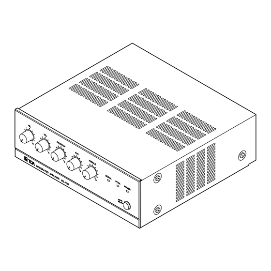
Page 6: Nomenclature And Functions Front
5. NOMENCLATURE AND FUNCTIONS [Front] PROGRAM MODULE SIGNAL PEAK POWER INTEGRATED AMPLIFIER BG-1120 This figure represents the BG-1120. 5. Microphone input volume control [MIC] 1. Power switch [ ON / OFF] Power is switched on and off with each depression Adjusts gain of microphone input. -
Page 7: Rear
[Rear] 14 15 22 23 Blank panel 120V 60Hz SENSE MAX 500W UNIT OUTLET MUTE MODULE PUSH PUSH BREAKER BREAKER RESET RESET PAGE PROGRAM BASS TREBLE UNSWITCHED – – OUTPUT 120 W OUTPUT 1 W MUTE 120V 60Hz PREAMP POWER 4Ω... -
Page 8: Input Connections
22. Mute selector switch [MUTE] 26. Power amplifier input terminal [POWER IN] Changes the type of mute operation. 0 dB, 10 kΩ, unbalanced, RCA jack. (Refer to p. 10, "Mute Function.") Used to connect input signals from external signal processing equipment such as limiters and 23. -
Page 9: Output Connections
10.4 Ω (BG-1060) 81.7 Ω (BG-1060) 21 Ω (BG-1030) 163 Ω (BG-1030) 42 Ω (BG-1015) 330 Ω (BG-1015) 4 Ω 25 V line 70 V line The terminals marked with the symbol are hazardous live. WARNING The external wiring to these terminals requires installation by an instructed person. -
Page 10: Plug-In Module Input Port
8. PLUG-IN MODULE INPUT PORT A single port for TOA plug-in modules is located on the unit's rear panel. Any 900 Series plug-in module can be inserted into this port. Note: Consult your nearest TOA dealer for selection of appropriate module types. -
Page 11: Mute Operation A
9.1.1. Mute operation A The mute function can be activated either by the TEL, MIC, or MODULE (PAGE) input signal, or by shorting the rear panel-mounted mute terminals. [Mute signal settings] Input signals to activate the mute function can be selected by the internal jumper wire settings. The TEL, MIC, and MODULE (PAGE) input signals are all factory-preset (Jumpers JP207, JP208, and JP209 are set.) as muting signals. -
Page 12: Tel Input Impedance Selection
9.2. TEL Input Impedance Selection The impedance is factory-preset to 10 kΩ. To switch to 600 Ω, change the position of the unit's internal jumper switch JP204. 600 Ω 10 kΩ T203 T202 T201 Jumper switch JP204 Preamplifier board 9.3. AUX, PROGRAM, MODULE (BGM) Output Selection Operations shown in the following tables can be enabled with the unit's internal jumper settings. -
Page 13: Changing Mic And Program Input Types
9.5. Changing MIC and PROGRAM Input Types Both MIC and PROGRAM inputs can be changed from electronically balanced to transformer balanced types with the following procedures. 9.5.1. MIC input • Install an optional IT-450 Line Transformer on the preamplifier board as shown below. •... -
Page 14: Rack Mounting Bracket Attachment
11. RACK MOUNTING BRACKET ATTACHMENT To mount the amplifier in a standard 19" equipment rack, use the optional MB-1000 Rack Mounting Bracket. Attach the MB-1000 to the amplifier using the 4 supplied screws. When using other screws, ensure that each screw is shorter than 16 mm (0.63"). -
Page 15: Dimensional Diagram
13. DIMENSIONAL DIAGRAM (Applicable to all models) Unit: mm (inches) 280 (11.02) 264 (10.39) 266.5 (10.49) This figure represents the BG-1015. 14. BLOCK DIAGRAM Phantom Power (DC 24 V) JP201 Option Mic Vol. –60 dB/600 Ω Mute Balanced JP207 I.T. -
Page 16: Specifications
15. SPECIFICATIONS BG-1015 BG-1030 BG-1060 BG-1120 Model No. Power Source 120 V AC, 60 Hz Rated Output 15 W 30 W 60 W 120 W Power Consumption Rated output 50 W 80 W 160 W 260 W Based on cUL standards...
Need help?
Do you have a question about the BG-1015 and is the answer not in the manual?
Questions and answers