Toa MA-725F Service Manual
Matrix amplifier, matrix pre-amplifier
Hide thumbs
Also See for MA-725F:
- Operating instructions manual (36 pages) ,
- Operating instructions manual (50 pages)
Table of Contents
Advertisement
Advertisement
Table of Contents

Related Manuals for Toa MA-725F


Summary of Contents for Toa MA-725F
- Page 1 SERVICE MANUAL MATRIX AMPLIFIER MATRIX PRE-AMPLIFIER MA-725F MM-700F...
-
Page 2: Table Of Contents
TABLE OF CONTENTS NOTE ON REPAIR WORK SAFETY ......................... 3 About lead-free solders ............................. 4 GENERAL DESCRIPTION ............................4 SPECIFICATIONS ..............................5 NOMENCLATURE AND FUNCTIONS ........................7 BLOCK DIAGRAM ..............................12 WIRING DIAGRAMS ............................... 13 TROUBLESHOOTING ............................15 MOUNTING DIAGRAMS ............................17 EXPLODED VIEWS AND PARTS LISTS ........................ -
Page 3: Note On Repair Work Safety
NOTE ON REPAIR WORK SAFETY Follow the instructions below, both to prevent accidents when making repairs and to ensure post-repair product safety. WARNING Hazardous voltages are present inside the equipment. When replacing the pc board assemblies or parts, be sure to disconnect the power cord to avoid electric shock that could result from accidental contact with these parts. -
Page 4: About Lead-Free Solders
GENERAL DESCRIPTION TOA's MA-725F matrix amplifier and MM-700F is all-in-one solution for multi-channel or multi-zone applications combined 6x4 audio matrix, DSP and 4ch Class-D amplifier (*) into one chassis. It is equipped with 4 independent line inputs, 2 MIC/LINE priority inputs. Each output has independent DSP preset adjustment also comes with input source matrix selection. -
Page 5: Specifications
SPECIFICATIONS ■SPECIFICATION (* 0dB = 1V) Model Number MA-725F Power Source 100 - 240V AC, 50/60Hz 1350 W (rated output), 200 W (based on cULus standards), 42.5 W (idle), Power Consumption 22 W or less (Stand-by) Frequency Response 20Hz - 20 kHz (-3dB / +1dB, LPF OFF) - Page 6 ■SPECIFICATION (* 0dB = 1V) Model Number MM-700F Power Source 100 - 240V AC, 50/60Hz Power Consumption 9W or less Frequency Response 20Hz - 20 kHz (-3dB / +1dB) Total Harmonic Distortion 1% or less, at 1kHz, rated output Certification cULus 60065, EN60065, EN55032, EN55020, FCC part15 class A Mic -60dB* / Line -10dB* selectable, 2.2kΩ, electrically balanced, Input...
-
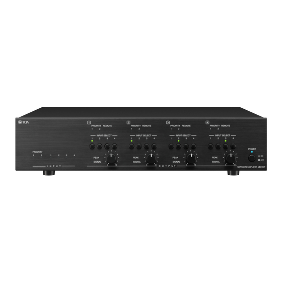
Page 7: Nomenclature And Functions
NOMENCLATURE AND FUNCTIONS [Front] POWER SIWITCH [ON /OFF] Press this switch to turn on the amplifier, press the switch again to turn off the amplifier. POWER INDICATOR [POWER] (Blue) During the power on process the indicator flashes, after amplifier is ready, the indicator lights. CH1 OUTPUT LEVEL CONTROL Adjust CH1 output level Note: The functionality of CH2, CH3, CH4 is the same as CH1. - Page 8 Select from LINE 1-4 inputs as the input source for amplifier CH1 output. Select again on the previous selected input turns off the selection of input source. Note: The functionality of CH2, CH3, CH4 is the same as CH1. (*) MA-725F only [Rear]...
- Page 9 11. AC inlet Connect the supplied power cord to this inlet. The socket-outlet should be installed near the equipment and the plug (disconnected device) shall be easily accessible. 12. Functional ground terminal [SIGNAL GND] Hum noise may be generated when external equipment is connected to the unit. Connecting this terminal to the functional ground terminal of the external equipment may reduce the hum noise.
- Page 10 21. PRIORITY FUNCTIONAL DIP SWITCH (PRIORITY 1, PRIORITY 2) Control the functionality of the PRIORITY 1 and PRIORITY 2 Switch No. PRIORITY 1/2 can be switched to CH1 output PRIORITY 1/2 cannot be switched to CH1 output PRIORITY 1/2 can be switched to CH2 output PRIORITY 1/2 cannot be switched to CH2 output PRIORITY 1/2 can be switched to CH3 output PRIORITY 1/2 cannot be switched to CH3 output...
- Page 11 33. SPEAKER OUTPUT TERMINAL (CH1, CH2, CH3, CH4) MA-725F: 70V/100V output (select by the 70V/100V OUTPUT MODE SWITCH (27)), removable terminal block type. Connect to speaker. MM-700F: 600Ω, 0dB*, removable terminal block type. Line level output. * 0 dB = 1Vrms (*) MA-725F only...
-
Page 12: Block Diagram
BLOCK DIAGRAM MA-725F MM-700F... -
Page 13: Wiring Diagrams
WIRING DIAGRAMS MA-725F... - Page 14 MM-700F...
-
Page 15: Troubleshooting
LINE OUTPUT CH1 ~ 4 -no output BGM PCB MOH ( INPUT 4 ) – no input The power consumption is correct after the power is on normally. (MA-725F is about 49 W; MM-700F is about 6W) LINE1~LINE4 input and speaker output are correct PRIORITY But after input the priority 1.2 signal, the front panel green light is off, no PRIORITY output... - Page 16 After the power turns on, the blue POWER light does not flash continuously, and the machine does not work. ETHERNET Back panel REMOTE CH1 ~ 4, no response (ETH) Back panel REMOTE LINK CH1-2, CH3-4, no action Back panel switch to EQ1 ~ 4, no Connected to the Internet route, the light is not on, fail to connect to the computer.
-
Page 17: Mounting Diagrams
MOUNTING DIAGRAMS ■MAIN POWER PCB (Part code : JB00228) - Page 18 ■Power Amp PCB (Part code : JB00230)
- Page 19 ■BGM+STB+SPK PCB (Part code : JB00229) BGM PCB SPK PCB STB PCB BGM PCB...
- Page 20 SPK PCB STB PCB...
- Page 21 ■ETH+PRI+Front+SW PCB (Part code : JB00227) SW PCB PRI PCB FRONT PCB ETH PCB PRI PCB FRONT PCB ETH PCB SW PCB...
- Page 22 Mechanical parts Part Code 1) Aluminum front panel D012503800 2) Bottom chassis D010600880 3) Top cover D210302380 4) Inner carton D320416250 5) EPE cushion sponge D321104170 6) DC FAN 214AJF0815HA D145100880...
-
Page 23: Exploded Views And Parts Lists
EXPLODED VIEWS AND PARTS LISTS... -
Page 27: Rework Sop
Rework SOP 1. STB PCB rework SOP 2. MAIN POWER PCB rework SOP 3. POWER AMP PCB rework SOP... - Page 28 STB PCB rework SOP 1. Open the outer carton and take out the inner carton (Total 2 units) 2. Open the inner carton.
- Page 29 3. Take out the unit and remove the side cushions from the unit. Remove the transparent packaging bag. 4. Remove all screws around the unit.
- Page 30 5. Lift the cover up.
- Page 31 6. Remove the two cables and 3 PCB fixing screws, then remove the upper PCB. 7. Remove 3 PCB fixed copper posts and remove the lower PCB.
- Page 32 8. Remove the screw and wire...
- Page 33 9.Change the new board Lock the screw and wire...
- Page 34 10.Put on lower PCB and lock the copper column 11.Put on upper PCB and lock the screw Install the wire...
- Page 35 12.Put on cover up and lock the screw 13. Rework is complete. Cover up the unit and screw back all 11 screws. Put on the transparent packaging bag. Put on the 2 side cushions for each unit. Place the manual and accessories. Place the unit into inner carton and seal the inner carton.
- Page 36 MAIN POWER PCB rework SOP 1. Open the outer carton and take out the inner carton (Total 2 units) 2. Open the inner carton.
- Page 37 3. Take out the unit and remove the side cushions from the unit. Remove the transparent packaging bag. 4. Remove all screws around the unit.
- Page 38 5. Lift the cover up.
- Page 39 6. Remove the wire,screw and heat sink Remove the screw and copper column...
- Page 40 When proceeding the replacement with SPS board, if there are no copper columns and washers at these three Please pay attention to the circled position, please use the spares directions of the two thermal we sent to you to fasten the screws conductive films.
- Page 41 7. Change the new board Lock the copper column,and confirm that the thermal conductive film is still.
- Page 42 8.Put on the heat sink,all the screw and wire 9. Rework is complete. Cover up the unit and screw back all 11 screws. Put on the transparent packaging bag. Put on the 2 side cushions for each unit. Place the manual and accessories. Place the unit into inner carton and seal the inner carton.
- Page 43 POWER AMP PCB rework SOP 1. Open the outer carton and take out the inner carton (Total 2 units) 2. Open the inner carton.
- Page 44 3. Take out the unit and remove the side cushions from the unit. Remove the transparent packaging bag. 4. Remove all screws around the unit.
- Page 45 5. Lift the cover up.
- Page 46 6. Remove wire,screw and heat sink...
- Page 47 7. Remove screw In case the new vision have to remove two more scew...
- Page 48 8.Change the new board Put the four thermal conductive film on the MOSFET...
- Page 49 Apply thermal grease to the circle Please take notice that these thermal pointed position and lock the heat sink. conductive films can not be damaged during the repairing process. The thermal grease needs to cover the thermistor and foam.
- Page 50 9.Put on heat sink and all the sink and screw 10. Rework is complete. Cover up the unit and screw back all 11 screws. Put on the transparent packaging bag. Put on the 2 side cushions for each unit. Place the manual and accessories. Place the unit into inner carton and seal the inner carton.
Need help?
Do you have a question about the MA-725F and is the answer not in the manual?
Questions and answers