GE Profile PHP900 Technical Service Manual
30/36-in. induction cooktop
Hide thumbs
Also See for Profile PHP900:
- Owner's manual (72 pages) ,
- Installation instructions manual (33 pages) ,
- Dimensions and installation information (2 pages)

Related Manuals for GE Profile PHP900


Summary of Contents for GE Profile PHP900
-
Page 1: Induction Cooktop
GE Consumer & Industrial Technical Service Guide April 2008 Profi le and Monogram 30- and 36-in. Induction Cooktop PHP900 PHP960 ZHU30 ZHU36 31-9164 GE Appliances General Electric Company Louisville, Kentucky 40225... - Page 2 If grounding wires, screws, straps, clips, nuts, or washers used to complete a path to ground are removed for service, they must be returned to their original position and properly fastened. GE Consumer & Industrial Technical Service Guide Copyright © 2008 All rights reserved.
-
Page 3: Table Of Contents
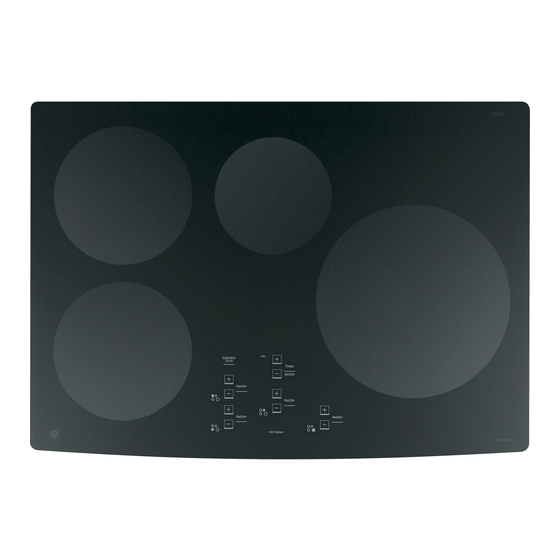
Table of Contents Appearance Defects ................................21 Component Locator Views ............................17 Control Features ................................8 Cooktop Components ..............................21 Cooktop Removal From Countertop ........................21 Diagnostics and Service Information ........................31 Elements ....................................22 Fans ......................................30 Filter Board ..................................29 Generator Boards ................................28 Glass Maintop ..................................22 Heat Shield ...................................26 Installation ................................... - Page 4 • Distinguished appearance ―Sleek cooktop fi ts fl ush with the countertop, and is surrounded completely in full-frame stainless steel trim. This cooktop can be installed above a GE or GE Profi le™ wall oven.** ® The four-burner models feature 1 ten-inch, 3700 W element, 2 seven-inch, 2500 W elements, and 1 six-inch 1800 W element.
- Page 5 Nomenclature Profi le Model Number P H P 9 0 0 D 1 M B B Brand Color Code P = Profi le BB = Black on Black SS = Stainless Steel H = Induction Model Year P = Cooktop M = 2007 Engineering Digit Feature Pack...
- Page 6 Introduction to Induction Cooking How Induction Cooking Works created by the induction coil is applied to only the Induction cooking uses high frequency (20-50 K hz) bottom of the pan. magnetic energy to heat a ferrous metal pan when it is placed over the induction coil. The induction fi...
- Page 7 Installation Models PHP900 and ZHU30 WARNING: Before beginning the installation, switch power off at the service panel and lock the 21-3/8″ service disconnecting means. When the service 29-3/4″ (21-1/2″ SS) at center (29-7/8″ SS) disconnecting means cannot be locked, securely 4-5/8“...
- Page 8 Control Features Features of your cooktop. Throughout this manual, features and appearance may vary from your model. NOTE: 30” models have cooking element location PHP900 30″ Cooktops indicators next to each control. PHP960 36″ Cooktops Feature Index Explained on page (Features and appearances may vary.)
-
Page 9: How Induction Cooking Works
How induction cooking works. ge.com The elements beneath the cooking Magnetic induction cooking requires surface produce a magnetic field that the use of cookware made of ferrous causes the electrons in the ferrous metals—metals to which magnets will metal pan to vibrate and produce stick, such as iron or steel. -
Page 10: Cookware Recommendations
Choosing the correct cookware to use. Cookware recommendations INCORRECT CORRECT Cookware must fully contact the surface of the cooking element. Use flat-bottomed pans sized to fit the cooking element and also to the amount of food being prepared. CAUTION: ■ The cooking elements may appear to be cool while turned ON and after they have been turned OFF. -
Page 11: Suitable Cookware
Suitable Cookware Use quality cookware with heavier Cookware “noise” bottoms for better heat distribution Slight sounds may be produced by and even cooking results. Choose different types of cookware. Heavier cookware made of magnetic stainless pans such as enameled cast iron Use flat-bottomed pans. -
Page 12: Setting The Controls
Setting the controls. Using the Touch Control. Touch the pad lightly with the flat part A "beep" sound can be heard with each of your fingertip. Touch the center of the touch to any pad. pad to ensure the cooktop response. Operating the Cooking Elements Each of the cooking elements have The induction circuit detects the pan and... -
Page 13: Power Sharing
Boost Setting Boost is the highest power level, designed NOTE: If the pan is removed, the display for large quantity rapid cooking and will flash “F” alternating to “H”. After 30 boiling. Boost will operate for a maximum seconds, the elements will turn off of 10 minutes. -
Page 14: Using The Kitchen Timer
Using the "L" Low Setting Place a pan with food onto the The Low setting will keep hot, cooked food induction element. The pan size at serving temperature. Always start with should match the indicator ring. hot food. Do not use to heat cold food. Touch the ON/OFF pad. -
Page 15: Using The Surface Elements
Using the surface elements. ge.com Error Alerts (Flashing “E”/”c” and “E” “o”) Error alerts indicate a temporary problem Touch the ON/OFF pad and allow the that may be corrected by the user. cooktop to cool for 30 to 45 minutes before operation can begin again. - Page 16 Operation Overview Normal Operation: The 36-in. cooktops have 2 fi lter boards that supply voltage to 3 generator boards. The left fi lter board When activated by the touch board, a fi lter board supplies voltage to the left generator board. The left supplies 240 VAC to 1 or 2 generator boards along generator board operates the 2 left-side elements.
-
Page 17: Component Locator Views
Component Locator Views 36-in. Models ZHU36 and PHP960 Glass Insulation Right Elements Wiring Cable Harness Insulation Left Touch Board Aluminum Left Heat Shield Generator Module Right Gene Filter Modu Board Filter Board Center Generator Board Left Side Right Side Generator Generator Board Board Right Generator Module Box... - Page 18 30-in. Models ZHU30 and PHP900 Glass Wiring Harness Cable Kit Elements Touch Board Shield Generator Module Filter Board Right Side Left Side Generator Generator Board Board Generator Module Box Protective Tape Fan Cover Burner Box Hold-Down Brackets with Electrical Thumbscrews...
- Page 19 36-in. Models ZHU36 and PHP960 Aluminum Heat Shield Touch Board Filter Board Filter Board Left Side Main Fan Thermal Thermal Cut-out Cut-out Left Side Generator Board Center Generator Board Right Side Generator Board (Continued next page) – 19 –...
- Page 20 30-in. Models ZHU30 and PHP900 Aluminum Heat Shield Touch Board Filter Board Thermal Cut-out Right Side Generator Board Left Side Generator Board – 20 –...
-
Page 21: Cooktop Components
Cooktop Components WARNING: Before servicing the cooktop, power Cooktop Removal From Countertop must be removed from the cooktop by turning the power off at the circuit breaker. To remove the cooktop from the countertop: WARNING: Sharp edges may be exposed when Caution: The hold-down brackets, heat baffl... -
Page 22: Glass Maintop
4. Turn the bracket inwards to avoid interference Glass Maintop when lifting the cooktop from the countertop. The glass maintop must be removed for element, sensor testing, and touch board replacement. The glass maintop is attached to the burner box with Bottom of Cooktop twelve 1/4-in hex-head screws (4 on the front, 4 on the back, and 2 on each side). - Page 23 4. Lift and fold back the insulation from the wire Note: On 11- and 8-in. elements, the choke must entry in the heat shield. be removed and transferred to the replacement element. The choke must be attached at the same location on the wires and secured with a plastic wire tie.
- Page 24 Note: The bottom of the touch board is attached to Note: If one or more functions do not work and no the heat shield with an adhesive foam cushion. apparent damage is present, the cause can be an excessive fl at-bottom drop of the packaged unit 3.
- Page 25 Tab Locations - 36-in. Model It may be necessary to insert the screwdriver in the right-side gap, push down on the screwdriver, and raise the heat shield even with the tab. In the following illustrations, the heat shield is out of alignment due to an excessive fl...
- Page 26 6. Remove the 20 Phillips-head screws from the Heat Shield top of the heat shield. (On 30-in. models, remove the 5 Phillips-head screws from the top of the To remove the heat shield: heat shield.) Remove the elements. (See Elements 36-in.
- Page 27 Correct way: Use side-to-side motion to remove the LINbus Connectors LINbus connector. Caution: To prevent damage to LINbus (Local Interconnect Networkbus) connections, properly use (as shown below) a Molex 69008-1070 tool when removing LINbus connectors. CORRECT Note: A Molex 69008-1070 tool will be provided with any part that requires the LINbus connectors to be removed.
- Page 28 6. Remove the two T-15 Torx screws that hold the Generator Boards generator to the module base. To remove the generator boards: 7. Lift the heat sink side and slide the generator board away from the 2 tabs on the module Remove the heat shield.
-
Page 29: Filter Board
5. Mark the location, then disconnect the black L1, Filter Board blue L2, and ground wire connections on the fi lter board. To remove the main fi lter board: 6. Disconnect the thermal cut-out, touch board, Remove the heat shield. (See Heat Shield and fan motor wire harnesses. - Page 30 30-in. Model Fan and 36-in Model Main Fan Fans The fan on the 30-in. model cools the left and right generator board heat sinks. The 36-in. model utilizes 2 fans. The main fan cools the right and center generator board heat sinks. An additional fan cools the left side generator board heat sink.
-
Page 31: Diagnostics And Service Information
Diagnostics and Service Information Failure Codes The cooktop operates a self-diagnostic mode when power is applied. The touch board has error codes that can be utilized by the service technician in order to quickly identify failed or improper operation of certain cooktop components. - Page 32 FAULT CAUSE CORRECTIVE ACTION Internal electronic failure on fi lter Check AC coming to home >208 VAC. board Replace fi lter board. Internal electronic failure on gen- Replace generator board. erator board Unknown error in system Visually check for loose wires/connections. Replace generator module.
-
Page 33: Linbus Connectors
Schematics and Wiring Diagrams WARNING: To prevent electrical shock, disconnect power to the cooktop prior to servicing. Model ZHU36 and PHP960 Aluminum Plate 2 Wire CAUTION: *A special tool is required when removing the connections (marked with an *) from the circuit boards. -
Page 34: Touch Board
Model ZHU30 and PHP900 Aluminum Plate Ground CAUTION: *A special tool is required when removing the connections (marked with an *) from the circuit boards. Damage to the circuit boards or cables may occur without the special tool. Touch Board... -
Page 35: Warranty
This warranty is extended to the original purchaser and any succeeding owner for products purchased for home use within the USA. If the product is located in an area where service by a GE Authorized Servicer is not available, you may be responsible for a trip charge or you may be required to bring the product to an Authorized GE Service location for service.