GE PHP960 Installation Instructions Manual
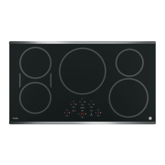
36"
Hide thumbs
Also See for PHP960:
- Owner's manual (72 pages) ,
- Instalation instructions (33 pages) ,
- Installation instructions manual (33 pages)
Table of Contents
Advertisement
Available languages
Available languages
Quick Links
Installation
Instructions
"If you have questions, call 800.GE.CARES or visit our website at: ge.com"
BEFORE YOU BEGIN
Read these instructions completely
and carefully.
IMPORTANT
•
for local inspector's use.
IMPORTANT
•
codes and ordinances.
• Note to Installer – Be sure to leave these
instructions with the Consumer.
• Note to Consumer – Keep these instructions
for future reference.
• Product failure due to improper installation is
not covered under the Warranty.
WARNING
properly grounded.
ATTENTION INSTALLER
•
COOKTOPS MUST BE HARD WIRED (DIRECT
WIRED) INTO AN APPROVED JUNCTION BOX.
A "PLUG AND RECEPTACLE" IS NOT PERMITTED
ON THESE PRODUCTS.
• Proper installation is the responsibility
of the installer and product failure due to
improper installation is NOT covered under
warranty.
PARTS INCLUDED
Baffle
(For all installations
except over an oven.)
Foam Tape
31-10668
(06 -07 JR)
— Save these instructions
— Observe all governing
— This appliance must be
— ALL
2 Hold-Down Brackets
6 Hex-Head Screws
2 Thumbscrews
36" Induction Cooktop
PHP960, ZHU36
MATERIALS YOU WILL NEED
Junction Box
(Sized for conduit
per local electrical
codes.)
TOOLS YOU WILL NEED
Phillips Head
Screwdriver
1/4" Nut Driver
Ruler or Straightedge
Safety Glasses
1
Large Size
Wire Nuts
Pencil
1/8" Drill Bit & Electric or
90º or Straight
Squeeze Connector
for 1" Conduit
Saber Saw
Hand Drill
Advertisement
Table of Contents

Subscribe to Our Youtube Channel
Related Manuals for GE PHP960


Summary of Contents for GE PHP960
- Page 1 Installation 36″ Induction Cooktop Instructions PHP960, ZHU36 “If you have questions, call 800.GE.CARES or visit our website at: ge.com” BEFORE YOU BEGIN MATERIALS YOU WILL NEED Read these instructions completely and carefully. IMPORTANT • — Save these instructions for local inspector’s use.
-
Page 2: Important Safety Instructions
Installation Instructions IMPORTANT SAFETY INSTRUCTIONS FOR YOUR SAFETY ELECTRICAL REQUIREMENTS • For Personal Safety, remove house fuse or open This appliance must be supplied with the proper circuit breaker before beginning installation. voltage and frequency, and connected to an Failure to do so could result in serious injury individual, properly grounded branch circuit, or death. -
Page 3: Pre-Installation Checklist
Installation Instructions PRE-INSTALLATION CHECKLIST BEFORE YOU BEGIN ADVANCE PLANNING Combination Installations WARNING – The electrical power to These cooktops may be installed in combination the cooktop supply line must be shut off while with an approved downdraft vent or a single oven. connections are being made. -
Page 4: Preparing The Opening
Installation Instructions PREPARING THE OPENING VERTICAL CLEARANCES (CONT.) The following MINIMUM clearance dimensions must be maintained. IMPORTANT: To ensure long life of the 13″ MAX. Depth of uprotected 2″ MIN. Clearance electronic components, allow a minimum of overhead cabinets from cutout to 12″... -
Page 5: Installing Options
Installation Instructions INSTALLING OPTIONS COOKTOP INSTALLATION WITH COOKTOP REQUIREMENTS A GE OR GE MONOGRAM 30″ The countertop must have a deep flat surface to DOWNDRAFT VENT accommodate the cooktop and vent. Countertops with a rolled front edge and backsplash will not The installation of the downdraft vent with provide the flat surface area required. -
Page 6: Power Supply
INSTALLING OPTIONS COOKTOP INSTALLATION OVER A POWER SUPPLY GE OR GE MONOGRAM SINGLE OVEN The oven requires a separate, properly grounded 20 Amp, 3-wire 208 or 240 volt, 60 Hz power supply. These cooktops may be installed over a single The cooktop requires a separate 50 Amp, 3-wire, oven. -
Page 7: Electrical Connections
Installation Instructions ELECTRICAL CONNECTIONS THREE-CONDUCTOR BRANCH CIRCUIT NEW CONSTRUCTION AND BRANCH CIRCUIT CONNECTION CONNECTION When connecting to a three-conductor branch WARNING: circuit, if local codes permit: Improper connection of aluminum house wiring to copper a. Connect the bare cooktop ground conductor leads can result in an electrical hazard or with the crimped ground (green) lead to the fire. -
Page 8: Installing The Cooktop
Installation Instructions INSTALLING THE COOKTOP PROTECT SURFACE OF COOKTOP ATTACH FOAM TAPE Place a towel or tablecloth onto the countertop. Apply the foam tape around the outer edge of the Lay the cooktop upside down onto the protected glass. Do not overlap the foam tape. surface. - Page 9 Installation Instructions INSERT COOKTOP INTO CUTOUT ATTACH HOLD-DOWN BRACKETS TO CABINET Insert the cooktop centered into the cutout opening. Make sure the front edge of the countertop is Open the cabinet door. Install the second screw parallel to the cooktop. Make final check that all through the bracket and tighten.
-
Page 10: Pre-Test Checklist
Installation Instructions CHECKLISTS PRE-TEST CHECKLIST OPERATION CHECKLIST Remove all protective film, if present, and any Remove all items from the top stickers. of the cooktop surface. Check to be sure that all wiring is secure and Turn on the power to the cooktop. not pinched or in contact with moving parts. -
Page 11: Instructions D'installation
Instructions Table de cuisson à induction de 36″ d’installation PHP960, ZHU36 « Si vous avez des questions, appelez au 800.561.3344 ou visitez notre site web : electromenagersge.ca » AVANT DE COMMENCER ÉQUIPEMENTS DONT VOUS AUREZ BESOIN Lisez attentivement la totalité de ces instructions. -
Page 12: Consignes De Sécurité Importantes
Instructions d’installation CONSIGNES DE SÉCURITÉ IMPORTANTES POUR VOTRE SÉCURITÉ CONDITIONS ÉLECTRIQUES REQUISES • Pour votre sécurité personnelle, enlevez le fusible Cet appareil doit être alimenté avec la tension et la ou coupez le disjoncteur avant de commencer fréquence correcte, branché sur un circuit dérivé l’installation. - Page 13 Instructions d’installation CHECK-LIST DE PRÉPARATION AVANT DE COMMENCER PLANIFICATION AVANCÉE AVERTISSEMENT – Installations combinées L’alimentation électrique de la table de cuisson doit être coupée Ces tables de cuisson peuvent être installées en pour effectuer les raccordements. Le non-respect combinaison avec un extracteur agréé ou un four de cette consigne peut provoquer des blessures simple.
- Page 14 Instructions d’installation PRÉPARATION DE L’OUVERTURE ESPACES LIBRES VERTICAUX (SUITE) L’espace libre doit avoir AU MINIMUM les dimensions suivantes. IMPORTANT : pour garantir la longévité des 33 cm (13″) MAX. de profondeur des 5 cm (2″) MIN. composants électroniques, laissez un espace placards supérieurs non protégés d’espace libre sur la libre minimal de 30 cm (12″) pour la circulation...
- Page 15 OPTION D’INSTALLATION—POUR GE MONOGRAM INSTALLATION COMBINÉE DE LA TABLE CONDITIONS REQUISES DU PLAN DE TRAVAIL DE CUISSON À INDUCTION GE OU GE Le plan de travail doit disposer d’une surface plate et MONOGRAM ET DE L’EXTRACTEUR 30” profonde pour accepter l’installation de la table de cuisson et de l’extracteur.
-
Page 16: Options D'installation
ALIMENTATION ÉLECTRIQUE CUISSON AU-DESSUS D’UN FOUR Le four nécessite une alimentation indépendante, SIMPLE GE OU GE MONOGRAM correctement raccordée à la terre de 20 ampères, à trois fils de 208/240 V CA, 60 Hz. La table de cuisson Ces tables de cuisson peuvent être installées nécessite une alimentation indépendante de 40... -
Page 17: Branchements Électriques
Instructions d’installation BRANCHEMENTS ÉLECTRIQUES CONSTRUCTION NEUVE ET RACCORDEMENT AU CIRCUIT DÉRIVÉ À RACCORDEMENT AU CIRCUIT DÉRIVÉ TROIS CONDUCTEURS Lors du branchement à un circuit dérivé à trois AVERTISSEMENT : conducteurs, si les normes locales le permettent : raccordement incorrect entre le a. -
Page 18: Installation De La Table De Cuisson
Instructions d’installation INSTALLATION DE LA TABLE DE CUISSON PROTÉGER LA SURFACE DE LA FIXEZ L’ISOLANT ADHÉSIF TABLE DE CUISSON Appliquez l’isolant adhésif autour de la bordure extérieure de la vitre. Ne faites pas chevaucher Placez une serviette ou une nappe sur le plan de l’isolant adhésif. - Page 19 Instructions d’installation INSÉREZ LA TABLE DE CUISSON SERREZ LES FIXATIONS DE DANS LA DÉCOUPE MAINTIEN AU MEUBLE Insérez la table de cuisson centrée dans l’ouverture Ouvrez la porte du meuble. Installez la deuxième vis découpée. Assurez-vous que la bordure avant du à...
- Page 20 Instructions d’installation CHECK-LISTS CHECK-LIST DE PRÉTEST CHECK-LIST DE FONCTIONNEMENT Enlevez la totalité du film protecteur, si applicable, et tous les autocollants. Enlevez tous les objets de la surface de la table de cuisson. Assurez-vous que tout le câblage est bien fixé sans pincement et qu’il n’est pas en contact Mettez sous tension la table de cuisson.
-
Page 21: Instrucciones De Instalación
Instrucciones Anafe de inducción de 36″ de instalación PHP900, ZHU30 “Si tiene alguna pregunta, llame a 800.GE.CARES o visite nuestro sitio Web en: ge.com” ANTES DE COMENZAR MATERIALES NECESARIOS Lea estas instrucciones por completo y con detenimiento. IMPORTANTE • — Guarde estas instrucciones para el uso de inspectores locales. -
Page 22: Instrucciones De Seguridad Importantes
Instrucciones de instalación INSTRUCCIONES DE SEGURIDAD IMPORTANTES PARA SU SEGURIDAD REQUERIMIENTOS ELÉCTRICOS • Para seguridad personal, quite los fusibles o abra Este artefacto debe abastecerse con el voltaje y el disyuntor antes de comenzar la instalación. No frecuencia adecuados y debe conectarse en un hacerlo puede provocar la muerte o una lesión circuito derivado individual con correcta conexión a personal grave. -
Page 23: Antes De Comenzar
Instrucciones de instalación LISTA DE CONTROL PRE-INSTALACIÓN ANTES DE COMENZAR PLANIFICACIÓN PREVIA Instalaciones en combinación ADVERTENCIA – La energía eléctrica Estos anafes pueden instalarse en combinación de la línea de abastecimiento del anafe debe con una ventilación de corriente descendente estar desconectada mientras se realizan las aprobada o un horno único. - Page 24 Instrucciones de instalación CÓMO PREPARAR LA ABERTURA ESPACIOS LIBRES VERTICALES Deben mantenerse las siguientes dimensiones (CONT.) MÍNIMAS de espacio libre. 13″ de profundidad MÁX en 2″ de espacio libre IMPORTANTE: Para garantizar una larga vida gabinetes aéreos sin protección MÍN desde el corte útil de los componentes electrónicos, deje 12″...
- Page 25 Instrucciones de instalación OPCIÓN DE INSTALACIÓN—PARA EL GE MONOGRAM SÓLO PARA LA INSTALACIÓN DE REQUERIMIENTOS DEL ANAFE COMBINACIÓN DE ANAFE DE La mesada debe contar con una superficie plana y INDUCCIÓN MONOGRAM Y profunda para que entren el anafe y la ventilación.
-
Page 26: Opciones De Instalación
Instrucciones de instalación OPCIONES DE INSTALACIÓN INSTALACIÓN DEL ANAFE SOBRE UN SUMINISTRO DE ENERGÍA HORNO GE O UN HORNO ÚNICO GE El horno requiere un suministro de energía individual MONOGRAM con adecuada conexión a tierra de 20 amperios, tres hilos 208 o 240 voltios, y 60 hercios. El anafe requiere Estos anafes pueden instalarse sobre un horno un suministro de energía individual de 40 amperios,... -
Page 27: Conexiones Eléctricas
Instrucciones de instalación CONEXIONES ELÉCTRICAS CONEXIÓN DE CONSTRUCCIÓN NUEVA CONEXIÓN DE CIRCUITO DERIVADO DE Y DE CIRCUITO DERIVADO TRES CONDUCTORES Cuando conecte un circuito derivado de tres ADVERTENCIA: conductores, si lo permiten los códigos locales: Una conexión inadecuada de cableado doméstico de a. - Page 28 Instrucciones de instalación CÓMO INSTALAR EL ANAFE PROTEJA LA SUPERFICIE DEL ANAFE COLOQUE CINTA DE ESPUMA Coloque una toalla o mantel sobre la mesada. Aplique la cinta de espuma alrededor de los Deposite el anafe dado vuelta sobre la superficie extremos exteriores del vidrio.
- Page 29 Instrucciones de instalación INTRODUZCA EL ANAFE EN LA CONECTE LOS SOPORTES DE ABERTURA SUJECIÓN AL GABINETE Coloque el anafe centrado dentro de la abertura Abra la puerta del gabinete. Instale el segundo cortada. Asegúrese de que el extremo frontal de la tornillo a través del soporte y ajuste.
-
Page 30: Listas De Control
Instrucciones de instalación LISTAS DE CONTROL LISTA DE CONTROL PREVIA A LA LISTA DE CONTROL DE PRUEBA FUNCIONAMIENTO Quite toda la película protectora, si la hubiera, Quite todos los elementos de la superficie del y todos los autoadhesivos. anafe. Verifique que todo el cableado esté seguro y Conecte la energía del anafe. - Page 31 Instrucciones de instalación NOTAS...
- Page 32 Instrucciones de instalación NOTAS...
Need help?
Do you have a question about the PHP960 and is the answer not in the manual?
Questions and answers