Table of Contents
Advertisement
Advertisement
Table of Contents

Related Manuals for HAMPTON BAY SOVANA 14412


Summary of Contents for HAMPTON BAY SOVANA 14412
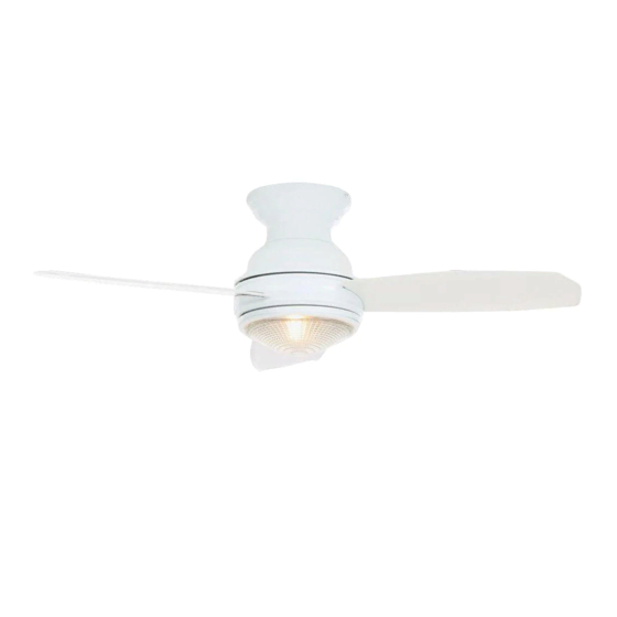
- Page 1 Model #14412 Item# 161-646 USE AND CARE GUIDE SOVANA 44 INCH CEILING FAN Questions, problems, missing parts? Before returning to the store call Hampton Bay Customer Service 8 a.m. - 6 p.m., EST, Monday-Friday 1-800-527-0998 HAMPTONBAY.COM THANK YOU THANK YOU...
-
Page 2: Table Of Contents
Table of Contents Table of Contents ............Operation ..............Remote Control Operating Instructions ........Safety Information ............Installing the Remote Control Holder .......... Warranty ................. Reverse Switch Operating Instructions ........Pre-installation .............. Care and Cleaning ............Specifications ................Troubleshooting ............Tools Required ................ -
Page 3: Safety Information
Safety Information □ Read and save these instructions. WARNING: To reduce the risk of fire or electronic shock, this fan must only use a UC7067RC solid-state speed control □ To reduce the risk of electric shock, ensure electricity has with a UC9050T wall control. been turned off at the circuit breaker or fuse box before beginning. -
Page 4: Warranty
Warranty We warrant the fan motor to be free from defects in workmanship and material present at time of shipment from the factory for a period of lifetime after the date of purchase by the original purchaser. We also warrant all other fan parts, excluding any glass or acrylic blades, to be free from defects in workmanship and material at the time of shipment from the factory for a period of one year after the date of purchase by the original purchaser. -
Page 5: Hardware Included
Pre-Installation (continued) HARDWARE INCLUDED HARDWARE INCLUDED NOTE: Hardware shown to actual size unless noted otherwise in the table below. Part Part Description Description Quantity Quantity Blade attachment hardware (3/16 in. x 17mm screws and lock washer) Plastic wire nut Balance kit (not to scale) Mounting bracket screws (preassembled) (3/16 in. -
Page 6: Package Contents
Pre-Installation (continued) PACKAGE CONTENTS PACKAGE CONTENTS Part Part Description Description Quantity Quantity Part Part Description Description Quantity Quantity Mounting bracket Receiver Fan motor assembly Remote control Blades Remote control holder Light kit mounting plate 100W halogen bulb Light kit plate 12V MN21/A23 battery Glass shade... -
Page 7: Installation
Installation MOUNTING OPTIONS MOUNTING OPTIONS WARNING: To reduce the risk of fire, electric shock, or personal injury, mount the fan to an outlet box marked acceptable for fan support using the screws provided with the outlet box. An outlet box commonly used for the support of lighting fixtures may not be acceptable for fan support and may need to be replaced. -
Page 8: Assembly
Assembly — Hanging the Fan Hanging the fan motor assembly Attaching the mounting bracket from the mounting plate to the electrical box □ Lift the fan into position by hanging the fan motor WARNING: To reduce the risk of fire, electric shock or assembly (B) onto the hook from the ceiling mounting other personal injury, mount the fan only to an outlet box or bracket (A) allowing it to hang freely. -
Page 9: Setting Up The Remote Control
Assembly — Setting up the Remote Control Preparing the receiver and remote control WARNING: To avoid possible electrical shock, ensure electricity is turned off at the main fuse box before wiring. CAUTION: The frequency switches on the receiving unit are covered with a rubber cover. -
Page 10: Making The Electrical Connections
Assembly — Making the Electrical Connections Making the electrical connections □ If your outlet box (JJ) has a ground wire (VV) (green WARNING: To avoid possible electrical shock, ensure or bare copper), connect it to the fan ground wires electricity is turned off at the main fuse box before wiring. (WW);... -
Page 11: Finishing The Fan Motor Installation
Assembly — Finishing the Fan Motor Installation Attaching the fan motor assembly Tightening the screws to the mounting bracket □ □ Loosen two of the four mounting bracket screws (DD) Install the two mounting bracket screws (DD) from the mounting bracket (A), and remove the other previously removed, and tighten all four mounting two screws (DD). -
Page 12: Attaching The Fan Blades
Assembly — Attaching the Fan Blades Fastening the blade assemblies to the motor WARNING: To reduce the risk of personal injury, do not bend the blade arms while installing, balancing the blades (C), or cleaning the fan. Do no insert foreign objects between rotating fan blades (C). -
Page 13: Installing The Light Kit
Assembly — Installing the Light Kit Attaching the light kit mounting Attaching the light kit plate to plate to the mounting ring the mounting plate □ □ Remove one of three mounting ring screws (HH) from While holding the light kit plate (E) under your fan (B), the mounting ring (YY) and loosen the other two make the polarized plug connections: screws. - Page 14 Assembly — Installing the Light Kit (continued) Finishing the light kit assembly and mounting the glass shade WARNING: Before starting installation, disconnect the power by turning off the circuit breaker or removing the fuse at the fuse box. Turning power off using the fan switch is not sufficient to prevent electric shock.
-
Page 15: Operation
Operation REMOTE CONTROL OPERATING INSTRUCTIONS REMOTE CONTROL OPERATING INSTRUCTIONS Install a 12V MN21/A23 battery (K) (included) in-to the remote control (H). To prevent damage to the remote control (H), remove the battery (K) if not used for long periods. □ Restore power to the ceiling fan and test for proper operation. -
Page 16: Reverse Switch Operating Instructions
Operation (continued) REVERSE SWITCH OPERATING INSTRUCTIONS REVERSE SWITCH OPERATING INSTRUCTIONS The reverse switch is located on the surface of the switch housing. This switch controls directions: forward (switch left) or reverse (switch right). NOTE: Wait for the fan to stop before reversing the direction of the blade rotation. -
Page 17: Troubleshooting
Troubleshooting WARNING: Make sure the power is off at the electrical panel box before you attempt any repairs. Refer to step 4 “Making the electrical connections” on page 10. Problem Problem Solution Solution □ Check main and branch circuit fuses or breakers. □... -
Page 18: Service Parts
Service Parts Part Part Description Description Part Part Description Description Mounting bracket Blade attachment hardware (3/16 in. x 17mm screws Fan motor assembly and lock washers) 3 blades Plastic wire nut Light kit mounting plate Balance kit Light kit plate Mounting bracket screws (3/16 in. - Page 19 Questions, problems, missing parts? Before returning to the store call Hampton Bay Customer Service 8 a.m. - 6 p.m., EST, Monday-Friday 1-800-527-0998 HAMPTONBAY.COM Retain this manual for future use. 11MA0620-1H000001-C...