Advertisement
3 1 1 8
INSTRUCTION MANUAL
November 2002 Revised edition 1
3118A981-01 02-11H Printed in Japan
Introduction
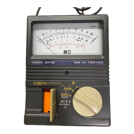
Thank you for purchasing the Hioki 3118 MΩ HiTESTER. To obtain
maximum performance from the product, please read this manual first,
and keep it handy for future reference.
Inspection
When you receive the product, inspect it carefully to ensure that no
damage occurred during shipping. If damage is evident, or if it fails to
operate according to the specifications, contact your dealer or Hioki
representative.
Maintenance and Service
To clean the product, wipe it gently with a soft cloth moistened with
water or mild detergent. Never use solvents such as benzene, alcohol,
acetone, ether, ketones, thinners or gasoline, as they can deform and
discolor the case.
If the product seems to be malfunctioning, confirm that the batteries are
not discharged, and that the test probes are not open circuited before
contacting your dealer or Hioki representative.
Pack the product carefully so that it will not be damaged during
shipment, and include a detailed written description of the problem. Hioki
cannot be responsible for damage that occurs during shipment.
Specifications
General Specifications
Operating
0 to 40
(32 to 104
), 90% RH max
temperature and
(with no condensations)
humidities
Storage temperature
-10 to 50
(-4 to 122
), 90% RH max
and humidities
(with no condensations)
Operating
Altitude up to 2000 m (6562 feet)
environment
Rated power voltage: 1.5 VDC X 6,
Power source
R6P manganese battery X 6
External power (DC8.5 V/600mA, MAX. 10 V)
Maximum rated power 4 VA
Continuous operating
Approx. 8 hours at 500 V, 1 MΩ
time
(using mannganese batteries)
3 kVAC 50/60 Hz for one minute
Dielectric strength
Between electric circuit and case
Dimensions
106W X 145H X 52D mm approx.
(excluding protrusions)
4.17"W X 5.71"H X 2.05"D approx.
Mass
500 g, (17.6 oz.) approx. (including batteries)
9294 TEST PROBE
9363 CARRYING CASE (3118-11)
Accessories
9364 CARRYING CASE (3118-12)
Instruction Manual, Instruction label
R6P manganese battery X 6, Spare fuse
9288 BREAKER PIN, 9289 TEST PROBE,
Option
9257 CONNECTION CORD
Specifications
Guaranteed at 23 5 (73 9
), 90% RH or less, for 1 year.
Model
3118-11
3118-12
Rated voltage
250 V
500 V
500 V
Maximum effective
50 MΩ
100 MΩ
200 MΩ
reading
1st effective
0.05 to 20 MΩ 0.1 to 50 MΩ
0.1 to 50 MΩ
2 to 500 MΩ
measurement
5% of scale reading
range
2nd effective
20 to 50MΩ
50 to 100MΩ
50 to 200MΩ 500 to 2000MΩ
measurement
10% of scale reading
range
0.7% of scale length
Other accuracy
(including 0 and
reading)
10% of rated voltage at infinity
Measurement
terminal voltage
90% min. of rated voltage at 1 MΩ
accuracy
(3118-12: 1000 V range at 20 MΩ)
5% of scale reading plus basic allowance at 1 MΩ
Effective of
(3118-12: 1000 V range at 20 MΩ)
temperature
(0 to 40 )
0.7% of scale length plus basic allowance at 0 and
Measurement
current (when
3.4 mA
short-circuited)
3 s or less at 1 MΩ or 0
Response time
(3118-12: 1000 V range at 20 MΩ)
Overload
protection
280 V rms
600 V rms
600 V rms
1100 V rms
(measurement
terminal)
Discharge function
Yes
No
Yes
Resistance range
0 to 100 Ω /
3% of scale length
and accuracy
Effective of
temperature
3% of scale length plus basic allowance
(0 to 40 )
Open terminal
310 mV max.
voltage
Overload
250 V rms
protection
(Fuse protection: 1 A/250 V with non-arcing type
AC voltage range
0 to 600 V
and accuracy
7% of maximum scale value (50/60 Hz)
Effective of
temperature
7% of maximum scale value
(0 to 40 )
Input resistance
Approx. 160 kΩ
Approx. 3.3 MΩ
Overload
700 V rms
protection
Safety
This manual contains information and warnings essential for safe
operation of the product and for maintaining it in safe operating condition.
Before using the product, be sure to carefully read the following safety
notes.
Safety Symbols
The
symbol printed on the product indicates that
the user should refer to a corresponding topic in the
manual (marked with the
relevant function.
In the manual, the
symbol indicates particularly
important information that the user should read before
using the product.
Indicates that dangerous voltage may be present at this
terminal.
Indicates AC (Alternating Current).
Indicates DC (Direct Current).
The following symbols in this manual indicate the relative importance of
cautions and warnings.
Indicates that incorrect operation presents an
DANGER
extreme hazard that could result in serious
injury or death to the user.
Indicates that incorrect operation presents a
WARNING
significant hazard that could result in serious
injury or death to the user.
Indicates that incorrect operation presents a
CAUTION
possibility of injury to the user or damage to
1000 V
the product.
2000 MΩ
Advisory items related to performance or
NOTE
correct operation of the product.
Notes on Use
DANGER
Before connecting probes to the product, check that the
probes are disconnected from the object to be measured.
WARNING
To avoid electric shock, do not allow the product to get
wet, and do not use it when your hands are wet.
Before using the product, make sure that the
insulation on the probes is undamaged and that no
bare conductors are improperly exposed. Using the
0.32 mA
product in such conditions could cause an electric
shock. Replace the test probes with the specified
Hioki Model 9294.
Do not use the product where it may be exposed to
corrosive or combustible gases. The product may be
damaged or cause an explosion.
CAUTION
No
Do not store or use the product where it could be exposed to
direct sunlight, high temperature or humidity, or condensation.
Under such conditions, the product may be damaged and
insulation may deteriorate so that it no longer meets
specifications.
To avoid damage to the product, protect it from vibration or
shock during transport and handling, and be especially careful
to avoid dropping.
NOTE
Before use check that batteries are charged. Replace the old batteries
with fresh one if they are low.
When not in use for a long time, to prevent possible corrosion caused
by battery leakage, remove the batteries before storage.
Always release the MEASURE button after use.
The meter display is glass, so avoid subjecting it to strong impacts.
This product is provided with a label containing measurement
instruction and precautions. After purchase, be sure to fix this label to
the battery cover on the back of the product.
Before use, check whether the product operates properly. You can do
this by performing Insulation Resistance Measurement, then pressing
the MEASURE button in the MΩ setting (the indicator should read
zero).
If the needle remains in the position, the fuse has blown. In this case,
replace the fuse with a new one of the same rating (refer to "Fuse and
Battery Replacement").
Fuse and Battery Replacement
To avoid electric shock when replacing the batteries,
first disconnect the test probes from the object to be
measured. Before using the product after replacing
the batteries, replace the cover and screw.
Do not mix old and new batteries, or different types of
batteries. Also, be careful to observe battery polarity
during installation. Otherwise, poor performance or
symbol) before using the
damage from battery leakage could result.
To avoid the possibility of explosion, do not short
circuit, disassemble or incinerate batteries.
Keep batteries away from children to prevent
accidental swallowing.
Replace the fuse only with one of the specified
characteristics and voltage and current ratings. Using
a non-specified fuse or shorting the fuse holder may
cause a life-threatening hazard.
Fuse type: MF51NR1-S 1 A, 250 V (non-arcing) 20 mm
X 5 mm dia.
1. Rotate the decorative screw with a
coin or similar object.
2. Remove the battery cover.
3. Insert six new batteries.
If the fuse has blown, replace it
with a new one.
WARNING
Battery cover
Spare fuse
Advertisement

Related Manuals for Hioki 3118


Summary of Contents for Hioki 3118
- Page 1 The following symbols in this manual indicate the relative importance of Introduction X 5 mm dia. 9294 TEST PROBE cautions and warnings. Thank you for purchasing the Hioki 3118 MΩ HiTESTER. To obtain 9363 CARRYING CASE (3118-11) Accessories 9364 CARRYING CASE (3118-12) Indicates that incorrect operation presents an...
-
Page 2: Parts List
After measuring a circuit with capacitance, release the MEASURE Using the Carrying Case 6. Earth measurement terminal button and set the function selector to 250 V (3118-11) or 500 V Source Connect the EARTH probe (black). (3118-12) before detaching the probes. This will activate the 3118 (primary 7.
Need help?
Do you have a question about the 3118 and is the answer not in the manual?
Questions and answers