
Related Manuals for Toa C-QA40


Summary of Contents for Toa C-QA40
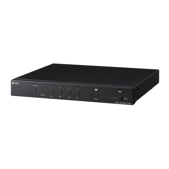
- Page 1 OPERATING INSTRUCTIONS QUAD ADAPTER C-QA40 Please follow the instructions in this manual to obtain the optimum results from this unit. We also recommend that you keep this manual handy for future reference.
-
Page 2: Table Of Contents
TABLE OF CONTENTS 1. SAFETY PRECAUTIONS ................3 2. GENERAL DESCRIPTION ................4 3. FEATURES ......................4 4. NOMENCLATURE AND FUNCTIONS Front ........................5 Rear ........................5 5. BASIC OPERATIONS 5.1. Switching on the Power ................... 6 5.2. Camera Image Selection (Monitor 2 Output Terminal) ........6 5.3. -
Page 3: Safety Precautions
AC outlet and shock. contact your nearest TOA dealer. Make no further attempt to operate the unit in this condition as this • When unplugging the power supply cord, be sure may cause fire or electric shock. -
Page 4: General Description
A fire or electric shock may result. 2. GENERAL DESCRIPTION TOA's C-QA40 Quad Adapter reduces the video images of up to 4 connected asynchronous color or black- and-white (B/W) cameras to quarter size, and displays these images on a monitor as a 4-segment split-screen display. -
Page 5: Nomenclature And Functions Front
4. NOMENCLATURE AND FUNCTIONS [Front] 1. Sequence/Clear Key Monitor 2 output terminal. When the setting screen Sequentially switches the outputs of cameras 1-4 is displayed, these keys are also used to move the at set time interval (p. 12) for monitor display cursor . -
Page 6: Basic Operations
5. BASIC OPERATIONS Operating Precautions : Please read this manual carefully to avoid operation errors. 5.1. Switching on the Power • Ensure that all connections, especially those of the power cables, are secure. • Switch ON the power by pressing the front panel Power switch, and check to confirm that the power lamp lights. -
Page 7: Using The Alarm & Remote Functions
5.3. Using the Alarm & Remote Functions • Select either "ALARM" or "REMOTE" in the Alarm/Remote settings shown on p. 17 (Item 4-1.). • For Alarm operations, select either "Make" or "Break" to activate an alarm depending on the type of sensor being connected (Item 4-2. -
Page 8: Freeze Screen Operations
5.4. Freeze Screen Operations 5.4.1. Freezing the screen in a 4-segment split-screen display F R E E Z E • Press the Channel Selector key while holding down the Quad Display key. The selected key's indicator lamp flashes and the corresponding channel title displayed on the monitor screen also flashes, indicating the selected channel has been placed in Freeze mode. -
Page 9: Operation Mode Settings
6. OPERATION MODE SETTINGS 6.1. Basic Setting Screen Operations 6.1.1. Setting screen display and operation Press the Menu key using a mechanical pen or other pointed stuff. The screen will then be switched to the setting screen display, and the menu screen will be displayed on the monitor. -
Page 10: Menu/Setting Item Table
6.2. Menu/Setting Item Table Setting Menu Menu Item Setting Items and Setting Contents Screen Menu (p. 9) 1. Sequence Switcher (p. 11) Automatic Sequential Switching Time Interval (p. 12) Sets the time interval to switch camera outputs in automatic sequential switching mode. Sequential Switching Skip Channel (p. -
Page 11: Initial Setting
6.3. Initial Setting Setting Item Initial Setting 3SEC DWELL TIME SEQUENCE SEQUENCE SKIP SWITCHER QUAD FULL SCREEN TITLE DISPLAY QUAD SCREEN Upper left POSITION Upper left Upper left Upper left Upper row Quad (upper screens) Quad (lower screens) Upper row TITLE SETTING ALARM REMOTE IN... -
Page 12: Automatic Sequential Switching Time Interval Setting [Dwell Time]
1-1. Automatic Sequential Switching Time Interval Setting [Dwell Time] Step 1. Using the [ ] and [ ] keys at the sequential switching S E Q U E N C E S W I T C H E R setting screen, move the cursor to Item [1. DWELL TIME]. -
Page 13: Title Display And Position Settings [Title Display]
2. Title Display and Position Settings [Title Display] [Setting screen displays and operations] M E N U Step 1. Using the [ ] and [ ] keys at the setting menu screen, move the cursor to Item [2. TITLE DISPLAY]. S E Q U E N C E S W I T C H E R The selected item will then flash as shown in the figure... -
Page 14: 4-Segment Split-Screen Title Display Setting [Quad Screen]
2-2. 4-Segment Split-Screen Title Display Setting [Quad Screen] Step 1. Using the [ ] and [ ] keys at the Title Display setting screen, move the cursor to Item [2. QUAD SCREEN]. T I T L E D I S P L A Y The selected item will then flash. -
Page 15: Title Setting [Title Setting]
[Setting for a 4-segment split-screen display] Step 1. Using the [ ] and [ ] keys at the Title Display setting T I T L E D I S P L A Y screen, move the cursor to [4. QUAD] for selection of the title setting position. - Page 16 Step 2. Press the Setting key. The Title Setting Camera Selection screen will then be T I T L E S E T T I N G displayed, and the selectable camera number will flash C H 1 C H 1 as shown in the figure on the right.
-
Page 17: Alarm/Remote Setting [Alarm/Remote]
4. Alarm/Remote Setting [Alarm/Remote] [Setting screen display and operation] Step 1. Using the [ ] and [ ] keys at the setting menu screen, move the cursor to Item [4. ALARM/REMOTE]. M E N U The selected item will then flash as shown in the figure S E Q U E N C E S W I T C H E R on the right. -
Page 18: Alarm Contact Input Detection Polarity Setting [Input Contact]
4-2. Alarm Contact Input Detection Polarity Setting [Input Contact] Step 1. Using the [ ] and [ ] keys at the Alarm/Remote A L A R M / R E M O T E setting screen, move the cursor to Item [2. INPUT CONTACT]. -
Page 19: Operation Setting After The Alarm Interval Elapses [Auto Return]
4-4. Operation Setting after the Alarm Interval Elapses [Auto Return] Step 1. Using the [ ] and [ ] keys at the Alarm/Remote setting screen, move the cursor to Item [4. AUTO A L A R M / R E M O T E RETURN]. -
Page 20: Monitor 1 Output Selection Setting [Monitor 1]
5-1. Monitor 1 Output Selection Setting [Monitor 1] Step 1. Using the [ ] and [ ] keys at the Others setting C O N D I T I O N screen, move the cursor to Item [1. MONITOR 1]. The selected item will then flash. -
Page 21: Background Color Setting [Back Color]
5-3. Background Color Setting [Back Color] Step 1. Using the [ ] and [ ] keys at the Others setting C O N D I T I O N screen, move the cursor to Item [3. BACK COLOR]. The selected item will then flash. M O N I T O R 1 Q U A D Step 2. -
Page 22: Connection Example
Make connections referring to the following connection diagram. Monitor TV Separate room Single-cable camera CAMERA OUT Camera 1 VIDEO IN CAMERA OUT Monitor 1 C-QA40 Camera 2 CAMERA OUT Camera 3 CAMERA OUT Camera Drive Unit Camera 4 Insert a cable pushing in the tab with a screwdriver blade. -
Page 23: Alarm/Remote Signal Input Terminal Connection
7.2. Alarm/Remote Signal Input Terminal Connection • Select either Alarm or Remote in "4-1. Alarm/Remote Make connections referring to the Signal Input Terminal Setting [Remote In]" on the setting following wiring diagram. screen. (p. 17) • Alarm is activated or remote control is performed by Alarm/Remote inputted opening or closing between the signal input terminal and grounding terminal using a no-voltage contact pulse. -
Page 24: When You Think There Is A Failure
9. WHEN YOU THINK THERE IS A FAILURE Symptom Cause • Power cable is not connected to AC wall outlet. • Power switch is not set to ON position. No image is displayed. • No video signal input from camera. •...
Need help?
Do you have a question about the C-QA40 and is the answer not in the manual?
Questions and answers