Toa NX-100 Installation Setup Manual
Network audio adapters
Hide thumbs
Also See for NX-100:
- Cookbook (70 pages) ,
- User manual (12 pages) ,
- Operation manual (6 pages)

Related Manuals for Toa NX-100


Summary of Contents for Toa NX-100
- Page 1 INSTALLATION SETUP MANUAL NETWORK AUDIO ADAPTERS NX-100 NX-100S Thank you for purchasing TOA's Network Audio Adapter. Please carefully follow the instructions in this manual to ensure long, trouble-free use of your equipment.
-
Page 2: Table Of Contents
5.4.2. Update information ................... 2-14 5.4.3. Installation folder configuration ................. 2-15 5.5. Uninstalling Each Software ..................2-15 Chapter 3: SYSTEM SETTINGS (NX-100 SETUP PROGRAM) 1. GENERAL DESCRIPTION 1.1. What is the NX-100 Setup Program? ................3-2 1.2. About Network Settings ....................3-2 1.3. - Page 3 6.6.1. Contact input setting ..................3-23 6.6.2. Contact output setting ..................3-25 6.7. Serial Bridge Setting ................3-27 NX-100 only 6.8. System Settings ......................3-29 6.9. Saving the Unit Setting Files ..................3-29 6.10. Reopening Unit Setting Files ..................3-30 6.11.
- Page 4 8.3. Stream Logs ....................... 4-24 8.4. Operation Status ......................4-26 9. SYSTEM MANAGEMENT ..................4-27 Chapter 5: OPERATION SETTINGS (NX-100 OPERATION PROGRAM) 1. NX-100 OPERATION PROGRAM SUMMARY ............ 5-2 2. STARTUP AND INITIAL SCREEN ................5-2 3. OPERATION SCREEN DESCRIPTION ..............
- Page 5 ....................6-4 1.6. Contact OFF Delay Time ....................6-4 1.7. Sampling Frequency Correction ................... 6-4 2. INDICATOR STATUS AND TROUBLESHOOTING ........... 6-5 3. IF A FAILURE IS DETECTED ................... 6-7 4. SPECIFICATIONS 4.1. NX-100 ......................... 6-9 4.2. NX-100S ........................6-10...
-
Page 6: Chapter 1: Before Installations And Settings
Chapter 1 BEFORE INSTALLATIONS AND SETTINGS... -
Page 7: General Description
Chapter 1: BEFORE INSTALLATIONS AND SETTINGS 1. GENERAL DESCRIPTION TOA's NX-100/100S Network Audio Adapter is specially developed to transmit high-quality audio signals and such control data as serial data over IP networks such as LAN or Internet in real time. -
Page 8: Nomenclature And Functions [Front]
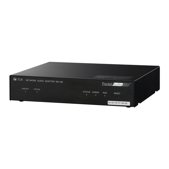
Chapter 1: BEFORE INSTALLATIONS AND SETTINGS 3. NOMENCLATURE AND FUNCTIONS [Front] • NX-100 NETWORK AUDIO ADAPTER NX-100 LNK/ACT FD/COL STATUS ERROR RESET 00-05-F9-FF-80-81 • NX-100S NETWORK AUDIO ADAPTER NX-100S INPUT LNK/ACT FD/COL SIGNAL PEAK STATUS ERROR RESET 00-05-F9-FF-80-81 1. LNK/ACT Indicator (Green) 5. -
Page 9: [Rear]
E: Ground (shield) 13. AC Adapter Terminal 19. Audio Input Terminal [AUDIO INPUT] [NX-100: AC ADAPTER, NX-100S: DC INPUT] A –58 to 0 dB/2 kΩ balanced input. Microphone Connect the AC adapter* to this terminal. or line level audio signals can be connected to * Use the AD-246 (optional) or its equivalent. - Page 10 Chapter 1: BEFORE INSTALLATIONS AND SETTINGS 20. Input Volume Control [INPUT VOLUME] Adjusts the audio input level. Turn the control clockwise to increase the level and counterclockwise to decrease it. NX-100S only Adjust the control so that the Input signal indicator (3) lights and the Input peak indicator (4) does not light.
-
Page 11: Setting Task Flows
Install the setup program, operation program, and Java Runtime Environment in the personal computer (PC). • The setup program can perform settings for multiple NX-100 and NX-100S units connected to the same network. • The operation program enables the PC to remotely operate the network PA system to make broadcasts. -
Page 12: Chapter 2: Unit And Software Installations
Chapter 2 UNIT AND SOFTWARE INSTALLATIONS... -
Page 13: Connections
Connect the AC adapter* to the unit's AC adapter terminal. Pinch the cord with a clamp and securely fix it. * Use the AC adapter AD-246 (optional) or the equivalent. As for the usable adapter, consult your TOA dealer. AC adapter... -
Page 14: Terminal Connections
Connect the microphone or other sound sources using 2-core shielded cable. • Network Connections The NX-100/100S automatically distinguishes between 10BASE-T and 100BASE-TX networks, and establishes a connection. For this connection, use a "straight" UTP Category 5 LAN (Ethernet) cable fitted with an RJ-45 connector. - Page 15 • RS-232C Interface Connections NX-100 only • Connections to the Control Input Terminal The NX-100 can be used to control such RS-232C Connect the control output terminals of all other components as DTE and DCE components over a connected units using 2 control lines.
-
Page 16: Connections To Terminal Plugs
Chapter 2: UNIT AND SOFTWARE INSTALLATIONS 2. CONNECTIONS TO TERMINAL PLUGS Wire the removable terminal plugs for power input (NX-100 only), audio input and output, and control input and output as follows: [Cable size and width to strip] Application Size... -
Page 17: Rack Mounting
3 x 4 tapping screw* Note M3 x 10 machine screw* Never use the screws supplied with the (supplied with NX-100/100S) MB-15B-BK to mount the bracket. The screws supplied with the MB-15B-BK are so long as to damage the internal parts, possibly causing the unit to fail. -
Page 18: Mac Addresses And Installation Locations
Be sure to record the relationship during installation to facilitate later network settings. * A 12-digit hexadecimal address number peculiar to and assigned to the network-connected unit. This figure represents the NX-100. NETWORK AUDIO ADAPTER NX-100 LNK/ACT... -
Page 19: Software Installation
Chapter 2: UNIT AND SOFTWARE INSTALLATIONS 5. SOFTWARE INSTALLATION 5.1. System Conditions The following minimum PC (personal computer) specifications are required in order to correctly operate the unit's software program. • OS: Windows 2000/XP • CPU: Pentium 800 MHz or greater •... -
Page 20: Installing Java Runtime Environment
Chapter 2: UNIT AND SOFTWARE INSTALLATIONS 5.3. Installing Java Runtime Environment The following procedures do not need to be carried out if J2SE Runtime Environment,5.0 Update 3 has already been installed in the PC. Step 1. Quit other activated applications before installation. Step 2. - Page 21 Chapter 2: UNIT AND SOFTWARE INSTALLATIONS Check the correct Runtime installation or version number from "Control Panel." Installation completion icon 2-10...
-
Page 22: Installing The Nx-100 Software
Enables integrated setting of the NX-100 and NX-100S from the PC. • NX-100 Operation Program Enables integrated setting of the NX-100 and NX-100S from the PC for broadcast activation. Install this software program to operate the unit from the PC. - Page 23 Chapter 2: UNIT AND SOFTWARE INSTALLATIONS Step 2. Click the Next button. The screen "Destination Folder" will be displayed. Step 3. When installing in a different folder from the one displayed, press the Change button to select the desired folder. Press the Next button if the currently displayed folder is correct. The "Setup Type"...
- Page 24 Chapter 2: UNIT AND SOFTWARE INSTALLATIONS Step 4. Select the NX-100 software program to install, then press the Next button. When installing simultaneously the NX-100 Setup Program (Installation Setting) and Operation Program, select "NX-100 Software Custom-Setup." [If something other than NX-100 Software Custom-Setup is selected] Installation will begin.
-
Page 25: Update Information
NX-100 Operation Program: 5.4.2. Update information • The latest versions of the following software and manuals are open to the public on the Toa's download site http://www.toa-products.com/international/: NX-100 firmware, NX-100 software (Setup program and Operation program), and Instruction manuals (Installation setup manual and Operations manual). Please download them from the above web site. -
Page 26: Installation Folder Configuration
Chapter 2: UNIT AND SOFTWARE INSTALLATIONS 5.4.3. Installation folder configuration The installed software program is stored by default in C:\Program Files\TOA\NX-100. The installation folder is configured as follows. (However, the unit setting file is only created after having been set by the setup program, and the unit operation log is created after the NX-100/100S unit's first actual operation.) -
Page 27: Chapter 3: System Settings (Nx-100 Setup Program)
Chapter 3 SYSTEM SETTINGS (NX-100 SETUP PROGRAM) -
Page 28: General Description
1.1. What is the NX-100 Setup Program? This program is used to set all the NX-100 and NX-100S units connected to a LAN. It also provides a simple display on the PC screen of operating data for multiple NX-100 and NX-100S units connected to a LAN. -
Page 29: Setup Software Configuration And Setting Items
The following two tools are made available: [Unit Scanning Tool] Performs unit scanning and network settings. Using this tool, first scan the NX-100 and NX-100S units connected to the LAN for the system initial setting. -
Page 30: Setting Procedure
Chapter 3: SYSTEM SETTINGS (NX-100 SETUP PROGRAM) 3. SETTING PROCEDURE Pattern 1: Initial On-Site Setup (1) Unit Scanning (Network Setting) • After scanning the unit using the Setup program's Unit Scanning Tool, set the IP address, default gateway, subnet mask, and unit name. - Page 31 If a data folder copy is saved, even when [Save in setting file format] is selected, it is possible to write the unit setting file into the NX-100 and NX-100S after recopying the previously saved and renamed folder to the data folder.
-
Page 32: Startup Of Installation Setting Program
Step 2. Enter the system name and password, then press the OK button. Note: Both the system name and password are case-sensitive. The default system name is factory-preset to "NX-100" and the password to "guest." To change them, refer to 3-31. - Page 33 Chapter 3: SYSTEM SETTINGS (NX-100 SETUP PROGRAM) Step 4. Click on [System Setting] when performing such system settings as broadcast configuration. When the settings are saved, a unit setting file is automatically created for each individual IP address and saved in the data folder. If a unit setting file of the same name already exists in the data folder, it is overwritten.
-
Page 34: Unit Scanning Tool
Scans the units connected to the LAN. Setting data can only be uploaded into the NX-100S and NX-100 units after each unit's IP address has been correctly set by way of either the Installation Setting Program's Unit Scanning Tool or a browser. -
Page 35: Menu
1. Upon completion of System Setting Tool settings, copy and save the data folder under a different name. If the data folder is copied, the unit setting file can be written into the NX-100 and the NX-100S after copying the renamed folder to the data folder, even when [Save in setting file format] is selected. -
Page 36: Help
Step 2. Either press the Unit Scan Button or select [Scan] → [Unit scan]. The MAC address, IP address, subnet mask, default gateway, and unit name of the NX-100 and NX-100S connected to the LAN will be displayed. Default values are factory-preset as follows: IP address: 192.168.1.1... -
Page 37: Changing The Unit Setting Values
Step 3. Press the Enter key or click on another cell. Step 4. After editing completion, press the Upload Button Caution Since the NX-100 and NX-100S units are automatically reset after uploading, any broadcasts currently in progress are stopped. 5.6. Automatic IP Address Assignment Set the IP address for the unit scanned. -
Page 38: Subnet Mask And Default Gateway Settings
Chapter 3: SYSTEM SETTINGS (NX-100 SETUP PROGRAM) 5.7. Subnet Mask and Default Gateway Settings The same subnet mask and default gateway numbers can be set for all selected units. Step 1. Tick the selection checkbox to select the unit. To select all units, select [Scan] → [Select all]. -
Page 39: System Setting Tool
Displays the unit names programmed into the system. (2) IP address Displays the unit IP addresses programmed into the system. (3) Web server port Displays the port number of the web server. (4) Unit type Displays either type of unit NX-100 or NX-100S. 3-13... -
Page 40: Menu
6.2.3. Setting Upload (Ctrl+U): Writes the settings currently being edited into the NX-100 and NX-100S. Download (Ctrl+D): Downloads the settings from the NX-100 and NX-100S, and displays them on the edit screen. (Not saved.) Firmware update: Updates the NX-100 and NX-100S firmware. -
Page 41: Buttons
Deletes NX-100 and NX-100S units from the network list (edit screen). (5) Upload button: Writes the currently edited settings into the NX-100 and NX-100S. (6) Download button: Downloads NX-100 and NX-100S settings and displays them on the edit screen. (Not saved.) 3-15... -
Page 42: Network Setting
Chapter 3: SYSTEM SETTINGS (NX-100 SETUP PROGRAM) 6.3. Network Setting Step 1. Click on the [Network] tab of the System Setting Tool. The setting screen will be displayed. Step 2. Set each item. (1) IP address Enter the unit's IP address. After the IP address is set with the Unit Scanning Tool, the assigned IP address is indicated when the unit setting file is loaded into the PC. - Page 43 Chapter 3: SYSTEM SETTINGS (NX-100 SETUP PROGRAM) [Start port No.] Enter the base number of the TCP port (other than web server, which is used by the unit). The default is "5000." Enter the number from within the range of 1 – 65532.
-
Page 44: Broadcast Spec Setting
Chapter 3: SYSTEM SETTINGS (NX-100 SETUP PROGRAM) 6.4. Broadcast Spec Setting Step 1. Click on the Broadcast Spec tab of the System Setting Tool. The setting screen will be displayed. Step 2. Select the usable bandwidth at Navigator. Selection of the usable bandwidth automatically sets recommended values except those related to Multicast. - Page 45 Chapter 3: SYSTEM SETTINGS (NX-100 SETUP PROGRAM) (2) Packet size Select the size of audio packet. The packet size cannot be changed when [Resend] is selected in the Packet loss recovery item. Smaller packet sizes result in a wider bandwidth, however delay times become shorter.
-
Page 46: Broadcast Pattern Setting
Chapter 3: SYSTEM SETTINGS (NX-100 SETUP PROGRAM) 6.5. Broadcast Pattern Setting 6.5.1. Setting new broadcast patterns Step 1. Click on the [Broadcast Pattern] tab of the System Setting Tool. The setting screen will be displayed. 3-20... - Page 47 Transmission: Transmits broadcast signals to the connected NX-100 and NX-100S units. Reception: Receives broadcast signals from the connected NX-100 and NX-100S units. Local: Makes broadcasts from the Audio Input of the NX-100 or NX-100S unit to its Audio Output. Selecting [Transmission] or [Reception] permits selection of the connected unit. Caution [Local] broadcasts cannot be made when the transmission sampling frequency is set to 32 kHz in the Broadcast Spec setting.
-
Page 48: Editing Broadcast Patterns
Chapter 3: SYSTEM SETTINGS (NX-100 SETUP PROGRAM) 6.5.2. Editing broadcast patterns Step 1. Click on the [Broadcast Pattern] tab of the System Setting Tool. The setting screen will be displayed. Step 2. Click on the broadcast pattern to be edited. -
Page 49: Contact Setting
Chapter 3: SYSTEM SETTINGS (NX-100 SETUP PROGRAM) 6.6. Contact Setting 6.6.1. Contact input setting Step 1. Click on the [Contact] tab of the System Setting Tool. Step 2. Click on the selection button for the contact input channel number. The setting contents will be displayed. - Page 50 Chapter 3: SYSTEM SETTINGS (NX-100 SETUP PROGRAM) Step 4. Set the type to [Momentary] or [Latch]. Momentary: The designated broadcast pattern or other unit's contact output is activated during the interval that input is ON. Activation stops while the input is OFF.
-
Page 51: Contact Output Setting
Chapter 3: SYSTEM SETTINGS (NX-100 SETUP PROGRAM) 6.6.2. Contact output setting Step 1. Click on the [Contact] tab of the System Setting Tool. Step 2. Click on the selection button for contact output channel numbers. The setting contents will be displayed. - Page 52 Chapter 3: SYSTEM SETTINGS (NX-100 SETUP PROGRAM) Step 5. Set the type to [Momentary] or [Latch]. Momentary: Provides output during the period between receiving an activation request and receiving a stop request. Latch: Provides 1 second of output upon receiving an activation request and 1 second of output upon receiving a stop request.
-
Page 53: Serial Bridge Setting
Chapter 3: SYSTEM SETTINGS (NX-100 SETUP PROGRAM) 6.7. Serial Bridge Setting NX-100 only Step 1. Click on the [Serial] tab of the System Setting Tool. Step 2. Tick [Enable serial port]. The setting screen will be displayed, allowing entry of each item. - Page 54 Tick the checkbox when transmitting and receiving raw data. Data with control information to be utilized between NX-100 units is usually transmitted, but raw data communications are generally carried out without such control information. However, when communications with other connected units are cut off, this cannot be detected.
-
Page 55: System Settings
6.9. Saving the Unit Setting Files Save the unit setting file to the specified location.* * The data folder is located in the installation folder (Default path: C:\Program Files\TOA\NX-100) of the setup program. The save location cannot be manually designated. -
Page 56: Reopening Unit Setting Files
[Update information] • The latest versions of the following software and manuals are open to the public on the TOA's download site http://www.toa-products.com/international/: NX-100 firmware, NX-100 software (Setup program and Operation program), and Instruction manuals (Installation setup manual and Operations manual). -
Page 57: Changing The System Name And Password
Chapter 3: SYSTEM SETTINGS (NX-100 SETUP PROGRAM) 7. CHANGING THE SYSTEM NAME AND PASSWORD Step 1. In the Installation Setting Program, click on [Password Change] on the initial screen. In the Management Setting Program, select [Help] → [Version data], and a dialog will then be displayed. -
Page 58: Chapter 4: System Settings (Setting Using Browser)
Chapter 4 SYSTEM SETTINGS (SETTING USING BROWSER) -
Page 59: Outline Of Setting Using Browser
Settings can also be changed without requiring installation of the dedicated NX-100 software by individually connecting to each NX-100/100S using the browser*. For NX-100/100S units connected by way of the NAT function, such as an access via internet, perform settings from the browser. - Page 60 • For the User name, enter the system name preset as default or by change. • Both the user name and password are case-sensitive. The default system name is factory-preset to "NX-100" and the password to "guest." To change them, refer to 4-28.
-
Page 61: Network Setting
3. NETWORK SETTING Set the NX-100/100S unit's network. This figure represents the NX-100. (1) IP Address Enter the NX-100/100S unit's IP address. (Factory-preset to "192.168.1.1.") (2) Subnet Mask Set the mask address. (Factory-preset to "255.255.255.0.") (3) Default Gateway Enter the gateway address if the unit is being used outside its assigned subnet. - Page 62 Enter the web server port number (Range: 1 – 65535; Factory-preset: 80) • Start port no. Enter the first TCP port number other than the HTTP, which is used by the NX-100/100S. (Range: 1 – 65532; Factory-preset: 5000) [UDP Port No. Assignment] Designate the first port number to be used by the UDP.
-
Page 63: Broadcast Spec Setting
Chapter 4: SYSTEM SETTINGS (SETTING USING BROWSER) 4. BROADCAST SPEC SETTING Set the specifications that determine broadcast streaming quality. The NX-100/100S starts its broadcasts based on this setting. This figure represents the NX-100. (1) Navigator Select the usable bandwidth and type of line, and press the Set button. A recommended values will then be set. - Page 64 Broadcast Spec settings. [Delay] The delay time is the duration until an audio signal received at the NX-100 and NX-100S passes through the network and is broadcast by other connected NX-100 and NX-100S units.
- Page 65 IP address and port number of the target unit. (6) Save button Updates the NX-100/100S setting file. Caution Never restart the unit or turn off the power during updates, or while the STATUS indicator on the front panel of the NX-100/100S is flashing.
-
Page 66: Broadcast Pattern Setting
1; Target multicast transmission units: 64) Create a new broadcast pattern by clicking on the Pattern Addition button, or select and edit a pattern which has already been programmed. This figure represents the NX-100. Pattern Selection Area Pattern Edit Area... -
Page 67: Pattern Selection Area
(4) Pattern Deletion button Deletes the selected broadcast pattern and updates the NX-100/100S setting file. Caution Never restart the unit or turn off the power during updates, or while the STATUS indicator on the front panel of the NX-100/100S is flashing. - Page 68 (3) Target Unit The IP addresses of the target NX-100 and NX-100S units are displayed. When "Transmission" is selected in the Direction setting, broadcasts are sent all added NX-100 and NX-100S target units. When "Reception" is selected, broadcasts are received from the added target NX-100 or NX-100S unit.
-
Page 69: Pattern Editing
This figure represents the NX-100. Press the Save button to program the edited pattern. Pressing the Save button will update the NX-100/100S setting file. Caution Never restart the unit or turn off the power during updates, or while the STATUS indicator on the front panel of the NX-100/100S is flashing. -
Page 70: Contact Setting
Chapter 4: SYSTEM SETTINGS (SETTING USING BROWSER) 6. CONTACT SETTING When the NX-100/100S unit's contact input is activated, its set broadcast pattern starts broadcasting while simultaneously enabling other unit's contact outputs. Here, contact input and output settings are performed. This figure represents the NX-100. -
Page 71: Contact Input Setting
Chapter 4: SYSTEM SETTINGS (SETTING USING BROWSER) 6.1. Contact Input Setting Set the broadcast pattern to be started, and the contact bridge. When the contact input is selected, the screen will switch over to the contact input setting screen. Select [Enable] and set the contact input contents. (1) Operation Mode Select from [Momentary] and [Latch]. - Page 72 Chapter 4: SYSTEM SETTINGS (SETTING USING BROWSER) (3) Broadcast Pattern The NX-100/100S unit's list of programmed broadcast patterns is displayed. Select the pattern to be started. Patterns which cannot be broadcast due to the Broadcast Spec settings are highlighted in red with a "NO"...
-
Page 73: Contact Output Setting
Chapter 4: SYSTEM SETTINGS (SETTING USING BROWSER) 6.2. Contact Output Setting Set the contact output to be activated when the NX-100/100S is enabled by other unit or the operation program. Selecting a contact output will switch the display to the contact output setting screen. Select "Enable"... - Page 74 For more information regarding OFF delay time, refer to p.6-4. (5) Save button Updates the NX-100/100S setting file. Caution Never restart the unit or turn off the power during updates, or while the STATUS indicator on the front panel of the NX-100/100S is flashing. 4-17...
-
Page 75: Serial Bridge Setting Nx-100 Only
[Protocol] Select the serial bridge communication configuration. TCP Server: The original unit carries out communications as a TCP server. The NX-100 unit connected to this server must be set as a TCP client in its protocol settings. TCP Client: The original unit carries out communications as a TCP client. The target NX-100 unit must be set as a TCP server in its protocol settings. - Page 76 Tick the checkbox when transmitting and receiving raw data. Data with control information to be utilized between NX-100 units is usually transmitted, but raw data communications are generally carried out without such control information. However, when communications with other connected units are cut off, this cannot be detected.
-
Page 77: Log Management
(1) Operation Log button Displays the NX-100/100S unit's operation log. (2) Stream Log button Displays streaming reception log. (3) Log Save button Saves log as a file in the PC. (4) Operation Status button Displays the NX-100/100S unit's current operation status. 4-20... -
Page 78: Operation Log
Chapter 4: SYSTEM SETTINGS (SETTING USING BROWSER) 8.1. Operation Log The operation log screen is displayed when the Operation Log button is pressed on the Log Management Menu screen. This figure represents the NX-100. [Operation button] (1) Latest button Updates the operation log to current data. - Page 79 Chapter 4: SYSTEM SETTINGS (SETTING USING BROWSER) [Items in the Table] (1) Time Indicates the time the event took place. (2) Category Indicates the type of log. SESSION: Communications between units REMOTE: Control by a PC SWITCH: Monitoring of the contact input and the contact control SERIAL: Serial bridge operating status SYSTEM:...
-
Page 80: Saving Operation Logs
Chapter 4: SYSTEM SETTINGS (SETTING USING BROWSER) 8.2. Saving Operation Logs Follow the procedures below to save logs to a PC: Step 1. Press the Operation Log Save button on the Log Management Menu screen. A dialog is displayed. Step 2. Press the Save Button. The screen for selecting the storage location is displayed. -
Page 81: Stream Logs
Chapter 4: SYSTEM SETTINGS (SETTING USING BROWSER) 8.3. Stream Logs The Stream Log screen is displayed when the Stream Log button is pressed on the Log Management Menu screen. This figure represents the NX-100. [Operation Button] (1) Refresh button Updates to the most recent data. - Page 82 Chapter 4: SYSTEM SETTINGS (SETTING USING BROWSER) [Items in the Table] (1) Current Stream • Stream Data • Reception Log Correct Reception: The number of packets received correctly. (The number of error packets or recovered packets is not included.) Error: The number of packets whose packet length and header data are not matched.
-
Page 83: Operation Status
Chapter 4: SYSTEM SETTINGS (SETTING USING BROWSER) 8.4. Operation Status The Operation Status screen is displayed when the Operation Status button is pressed on the Log Management Menu screen. This figure represents the NX-100. [Operation Button] (1) Refresh button Updates status to the most recent data. -
Page 84: System Management
Chapter 4: SYSTEM SETTINGS (SETTING USING BROWSER) 9. SYSTEM MANAGEMENT This figure represents the NX-100. Note The System Management Utility area is not displayed when in Management Setting mode. [Unit Data] (1) Unit Name Enter the NX-100/100S unit's name. (2) Audio Input Unit Name Enter a name when connecting the audio input unit. - Page 85 Chapter 4: SYSTEM SETTINGS (SETTING USING BROWSER) (4) Unit Data Change button Updates only system setting data in the NX-100/100S setting file. Caution Never restart the unit or turn off the power during updates, or while the STATUS indicator on the front panel of the NX-100/100S is flashing.
- Page 86 Step 2. Select the backup file (.cfg extension), then press the Upload button. Update of the setting file begins. Caution Never restart the unit or turn off the power during updates, or while the STATUS indicator on the front panel of the NX-100/100S is flashing. 4-29...
- Page 87 Chapter 4: SYSTEM SETTINGS (SETTING USING BROWSER) (2) Setting File Download Backs up the setting file. Step 1. Press the Download button. A dialog is displayed. Step 2. Press the Save button. A dialog is displayed. Step 3. Select the save destination and enter a filename. The default filename "[IP address].cfg"...
- Page 88 NX-100/100S is flashing. Tips • The latest versions of the following software and manuals are open to the public on the Toa's download site http://www.toa-products.com/international/: NX-100 firmware, NX-100 software (Setup program and Operation program), and Instruction manuals (Installation setup manual and Operations manual).
-
Page 89: Chapter 5: Operation Settings (Nx-100 Operation Program)
Chapter 5 OPERATION SETTINGS (NX-100 OPERATION PROGRAM) -
Page 90: Operation Program Summary
For more information concerning broadcast pattern settings, refer to Chapters 3 and 4. The NX-100's and NX-100S' contact output is controlled via the network. Up to 64 units x 8 channels can be controlled per button. 2. STARTUP AND INITIAL SCREEN Either double-click on the Operation program icon created on the desktop at the time of program installation or double-click on the application [nx100_control.jar] installed in the software folder. -
Page 91: Operation Screen Description
Chapter 5: OPERATION SETTINGS (NX-100 OPERATION PROGRAM) 3. OPERATION SCREEN DESCRIPTION This section explains the screen layout, using the accompanying operation setting screen as an example. (1) Selection Button Selects the broadcast pattern and contact output to be activated. The number of buttons programmed is 50 by default. -
Page 92: Menu
Button setting: Set the Selection button and the Group button. Unit settings: If there is a unit that has not yet been programmed into the system using the NX-100 setup program, select this menu item to add it as the operable unit. -
Page 93: Setting Procedures Using The Operation Program
5. SETTING PROCEDURES USING THE OPERATION PROGRAM Before performing the setting using the Operation program Set the NX-100 and NX-100S units in the system using the NX-100 Setup program. Broadcast settings that will be activated by the operation program must all be programmed into each connected unit as the "broadcast pattern."... -
Page 94: Unit Setting Addition
Chapter 4), add the unit setting using the following procedure: Step 1. Turn on the power to the NX-100 and NX-100S units for which the unit setting is to be added to make connections possible. Step 2. Start up the Operation program and select Setting → Unit settings. - Page 95 Pressing the Cancel button cancels the setting change. Setting can be attempted again after confirming the setting contents. • To delete an NX-100 or NX-100S unit from the Unit Settings screen list, select the desired unit and press the Delete button.
-
Page 96: Editting The Button Layout
OK button. Notes • Both the system name and the password are case-sensitive. • The default system name is preset to "NX-100" and the password to "guest" when the unit is shipped from the factory. To change, refer to p. 3-31 4-28. - Page 97 (1) Enable start button When the box is unchecked, the Start button on the operation screen is disabled and hidden. In this case, pressing the Selection or Group button automatically starts connection to the NX-100 or NX-100S programmed for that button.
-
Page 98: Setting The Selection Button Contents
Chapter 5: OPERATION SETTINGS (NX-100 OPERATION PROGRAM) 8. SETTING THE SELECTION BUTTON CONTENTS Program the broadcast pattern and the contact output activation setting into the Selection button. Step 1. Click on the Single selection button tab on the Button Setting screen 5-8). - Page 99 Step 5. Check the broadcast pattern to be activated in the Broadcast pattern list. Tips • The Broadcast pattern list displays all patterns that have been programmed into all NX-100 and NX- 100S units in the system, including the NX-100 and NX-100S units added in the unit setting procedure 5-6).
- Page 100 Chapter 5: OPERATION SETTINGS (NX-100 OPERATION PROGRAM) Step 7. Check the contact channel number to be used. To clear the setting contents of all NX-100 and NX-100S contact outputs, press the leftmost Clear button in the Edit area. Step 8. Press the OK button after completing all editing tasks.
-
Page 101: Setting The Group Button Contents
Chapter 5: OPERATION SETTINGS (NX-100 OPERATION PROGRAM) 9. SETTING THE GROUP BUTTON CONTENTS The Group button is used to simultaneously select two or more Selection buttons. Program the desired Selection buttons into the Group button. Step 1. Click on the Group button tab on the Button Setting screen 5-8). - Page 102 Step 7. Press the OK button after completing all editing tasks. The setting contents are saved to the data folder located in the installation folder (default path: C:\Program Files\TOA\NX-100) of the software program, and the Button Setting screen is closed. (Setting screen example)
-
Page 103: Error Messages
Chapter 5: OPERATION SETTINGS (NX-100 OPERATION PROGRAM) 10. ERROR MESSAGES If any of the following messages is displayed in the message display area, the NX-100/100S may be malfunctioning or have failed. Message Points to Check • "OO" connection failure. The NX-100 or NX-100S unit may have •... - Page 104 Chapter 6 APPENDIX...
-
Page 105: Explanation
The fixed global IP address must be assigned to the units connected via the Internet. When selecting an NX-100 or NX-100S which is connected through the Internet as the "target connection unit" for a broadcast pattern, contact or serial bridge* in NX-100 or NX-100S unit setting, the fixed global IP address must be designated. -
Page 106: Network Address Translation (Nat) And Setup Software Programs
Unit A by Router 1. Note that the NX-100 Setup program is not designed to enable the NAT function. Use a browser to select units connected by way of the NAT as the target connection unit for the broadcast pattern, contact or serial bridge* in the NX-100 and NX-100S unit settings. -
Page 107: Multicast And Simultaneous Multiple Broadcasts
The NX-100 and NX-100S convert audio data into IP packets to carry out communications. According to the condition of the network to be used, packets may be lost, deteriorating sound quality. The NX-100 and NX- 100S offer the following 3 different selection modes for recovering such lost packets. -
Page 108: Indicator Status And Troubleshooting
Continues for 30 seconds after the (for 30 seconds) unit is turned on. If this status remains unchanged over 30 seconds, this shows unit failure. Contact your TOA dealer. No audio signals Normal condition when broadcast is input and output not performed. - Page 109 This may cause intermittent sound when audio signals are transmitted. → It is preferable to use the NX-100/100S in full-duplex communications. Firmware exception handling occurrence → Push the front-mounted Reset button to restart the unit operation.
-
Page 110: If A Failure Is Detected
Turn power on again. Confirm that LAN cable is correctly connected. Confirm that the NX-100/100S is connected to the correct switching LNK/ACT LED does not light. hub's port and that the proper type of cable is used for the connection. - Page 111 Other malfunctions lights, check log. Refer to p. 4-21, Operation Log, to confirm log contents. Incorrect settings, or NX-100 or NX-100S failure may be the cause. Error message is displayed during operation using Operation program. → Refer to p. 5-15, Error Messages, for details.
-
Page 112: Nx-100
Note: The design and specifications are subject to change without notice for improvement. • Optional products Rack mounting bracket: MB-15B-BK (for rack-mounting one NX-100 unit) MB-15B-J (for rack-mounting two NX-100 units) AC adapter: AD-246 Note: When you need the AC adapter, be sure to consult your TOA dealer. -
Page 113: Nx-100S
Note: The design and specifications are subject to change without notice for improvement. • Optional products Rack mounting bracket: MB-15B-BK (for rack-mounting one NX-100S unit) MB-15B-J (for rack-mounting two NX-100S units) AC adapter: AD-246 Note: When you need the AC adapter, be sure to consult your TOA dealer. 6-10... - Page 114 URL: http://www.toa.jp/ 200708...
Need help?
Do you have a question about the NX-100 and is the answer not in the manual?
Questions and answers