Toa NX-100 Cookbook
Network audio adapters
Hide thumbs
Also See for NX-100:
- Installation setup manual (114 pages) ,
- User manual (12 pages) ,
- Operation manual (6 pages)
Table of Contents
Advertisement
Quick Links
Advertisement
Table of Contents

Related Manuals for Toa NX-100


Summary of Contents for Toa NX-100
-
Page 2: General Description
GENERAL DESCRIPTION General Description The NX-100 Network Audio Adapter can transmit high-quality audio signals and such control data as serial data over IP networks, such as LAN or Internet, in real time. It is especially useful when transmitting audio signals to remote locations, as Internet use keeps running costs lower than the use of dedicated lines. - Page 3 Using IP to transmit audio signals over the internet allows low cost operation rather than dedicated lines. ● The NX-100 is equipped with a DC input to allow operation on AC as well as ● Software-driven operational menus enhance ease of use.
-
Page 4: Network Audio Adapter Nx
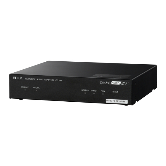
NOMENCLATURE & FUNCTION Network Audio Adapter NX-100 Status Indicator (Yellow) [Front] Remains lit during broadcasts. Flashes while the unit is writing data into the internal storage medium (flash memory). NETWORK AUDIO ADAPTER NX-100 LNK/ACT FD/COL LNK/ACT Indicator (Green) FD/COL Indicator (Yellow) -
Page 5: Application Example
Unattended Station A (172.16.0.2/16) ••• Line Communications panel (equipped with “Call in Progress” indicator) Control Office (172.16.0.1/16) C-out 1,2ch NX-100 “Calling up” indicator LED C-in 1-8ch Operating switch box Microphone Powered Speaker Unattended Station B (172.16.0.3/16) ••• Line... - Page 6 APPLICATION EXAMPLE-1 Passenger Handling System for Unattended Railway Stations Click (Scanning start) -1-2 UNIT SCAN-1 Click “Unit Scan (Network Setting)”...
-
Page 7: Network Setting
APPLICATION EXAMPLE-1 Passenger Handling System for Unattended Railway Stations Scanning Complete Change IP address -1-3 Network Setting-1 Change Unit name Change Subnet mask and Default gateway as required. (There is no in a change by this example) - Page 8 APPLICATION EXAMPLE-1 Passenger Handling System for Unattended Railway Stations 1) Click (Change settings) 2) Check all units 1) Confirm changed data 2) Click “File” 3) Select “Save in setting file format” -1-4 Network Setting-2...
-
Page 9: System Setting
APPLICATION EXAMPLE-1 Passenger Handling System for Unattended Railway Stations Broadcast Spec Setting for Office (1) Select “office” Broadcast Spec Setting for Office (2) SYSTEM SETTING-1 Click “System Setting” -1-5 1) Click “Broadcast Spec” 2) Change packet size from 64 to 128 3) Confirm that there is not “Two-ways streaming”... - Page 10 APPLICATION EXAMPLE-1 Passenger Handling System for Unattended Railway Stations Broadcast Pattern Setting for Office (1) Broadcast Pattern Setting for Office (2) SYSTEM SETTING-2 -1-6 1) Click “Broadcast Pattern” 2) Click “Add” 3) Input name 4) Click “A station” 1) Click “Add”...
- Page 11 APPLICATION EXAMPLE-1 Passenger Handling System for Unattended Railway Stations Broadcast Pattern Setting for Office (3) Broadcast Pattern Setting for Office (4) SYSTEM SETTING-3 -1-7 1) Click “Add” 2) Input name 3) Change “Direction” to “Reception” 4) Click “A station” 1) Click “Add”...
- Page 12 APPLICATION EXAMPLE-1 Passenger Handling System for Unattended Railway Stations Contact Input Setting for Office (1) 6) Click “A station” 7) Click “5” Contact Input Setting for Office (2) 5) Click “B station” 6) Click “5” SYSTEM SETTING-4 -1-8 1) Click “Contact”...
- Page 13 APPLICATION EXAMPLE-1 Passenger Handling System for Unattended Railway Stations Contact Input Setting for Office (3) 5) Click “A station” 6) Click “4” Contact Input Setting for Office (4) 4) Click “B station” 5) Click “4” SYSTEM SETTING-5 -1-9 1) Click “Input 3” 2) Click “Enable contact”...
- Page 14 APPLICATION EXAMPLE-1 Passenger Handling System for Unattended Railway Stations Contact Input Setting for Office (5) 3) Click “A station” 4) Click “1” and “4” Contact Input Setting for Office (6) 3) Click “B station” 4) Click “1” and “4” -1-10 SYSTEM SETTING-6 1) Click “Input 5”...
- Page 15 APPLICATION EXAMPLE-1 Passenger Handling System for Unattended Railway Stations Contact Input Setting for Office (7) 3) Click “office” and “A station” Contact Input Setting for Office (8) 3) Click “office” 5) Click “B station” -1-11 SYSTEM SETTING-7 1) Click “Input 7” 2) Click “Enable contact”...
- Page 16 APPLICATION EXAMPLE-1 Passenger Handling System for Unattended Railway Stations Contact Input Setting for A Station (1) 1) Select “A station” 4) Click “office” 6) Click “A station” Contact Input Setting for A Station (2) 3) Click “office” 5) Click “A station” -1-12 SYSTEM SETTING-8 2) Click “Input 1”...
- Page 17 APPLICATION EXAMPLE-1 Passenger Handling System for Unattended Railway Stations Contact Input Setting for B Station (1) 1) Select “A station” 4) Click “office” 6) Click “B station” Contact Input Setting for B Station (2) 3) Click “office” 5) Click “B station” -1-13 SYSTEM SETTING-9 2) Click “Input 1”...
- Page 18 APPLICATION EXAMPLE-1 SYSTEM SETTING-10 Passenger Handling System for Unattended Railway Stations Save 1) Click “File” 2) Select “Save to file” -1-14...
- Page 19 Securities Trading Companies Businesses such as these require cost-effective and versatile communications systems that facilitate realtime communication between various offices and a head office. TOA systems provide the communication reliability that these companies absolutely require and make it easy for all offices to receive important announcements and messages at the same time.
- Page 20 APPLICATION EXAMPLE-2 Transaction Information Transmission System for Securities Trading Companies Initial Screen Set IP address and name beforehand Broadcast Spec Setting 1) Select “TOKYO” Reception Pattern Setting for All Call SYSTEM SETTING-1 2) Click 3) Select “128” 4) Confirm that there is not 1) Click “Broadcast Pattern”...
- Page 21 APPLICATION EXAMPLE-2 SYSTEM SETTING-2 Transaction Information Transmission System for Securities Trading Companies Transmission Pattern Setting for Sapporo 1) Click “Broadcast Pattern” 2) Click “Add” 3) Input name 4) Check “SAPPORO” Reception Pattern Setting for Sapporo 1) Click “Add” 2) Input name 3) Change “Reception”...
- Page 22 APPLICATION EXAMPLE-2 Transaction Information Transmission System for Securities Trading Companies Transmission Pattern Setting for Sendai Reception Pattern Setting for Sendai SYSTEM SETTING-3 -2-4 1) Click “Broadcast Pattern” 2) Click “Add” 3) Input name 4) Check “SENDAI” 1) Click “Add” 2) Input name 3) Change “Reception”...
- Page 23 APPLICATION EXAMPLE-2 SYSTEM SETTING-4 Transaction Information Transmission System for Securities Trading Companies Transmission Pattern Setting for Yokohama 1) Click “Broadcast Pattern” 2) Click “Add” 3) Input name 4) Check “YOKOHAMA” Reception Pattern Setting for Yokohama 1) Click “Add” 2) Input name 3) Change “Reception”...
- Page 24 APPLICATION EXAMPLE-2 Transaction Information Transmission System for Securities Trading Companies Transmission Pattern Setting for Nagoya Reception Pattern Setting for Nagoya SYSTEM SETTING-5 -2-6 1) Click “Broadcast Pattern” 2) Click “Add” 3) Input name 4) Check “NAGOYA” 1) Click “Add” 2) Input name 3) Change “Reception”...
- Page 25 APPLICATION EXAMPLE-2 Transaction Information Transmission System for Securities Trading Companies Transmission Pattern Setting for Osaka Reception Pattern Setting for Osaka SYSTEM SETTING-6 -2-7 1) Click “Broadcast Pattern” 2) Click “Add” 3) Input name 4) Check “OSAKA” 1) Click “Add” 2) Input name 3) Change “Reception”...
- Page 26 APPLICATION EXAMPLE-2 SYSTEM SETTING-7 Transaction Information Transmission System for Securities Trading Companies Transmission Pattern Setting for Takamatsu 1) Click “Broadcast Pattern” 2) Click “Add” 3) Input name 4) Check “TAKAMATSU” Reception Pattern Setting for Takamatsu 1) Click “Add” 2) Input name 3) Change “Reception”...
- Page 27 APPLICATION EXAMPLE-2 Transaction Information Transmission System for Securities Trading Companies Transmission Pattern Setting for Fukuoka Reception Pattern Setting for Fukuoka SYSTEM SETTING-8 -2-9 1) Click “Broadcast Pattern” 2) Click “Add” 3) Input name 4) Check “FUKUOKA” 1) Click “Add” 2) Input name 3) Change “Reception”...
- Page 28 APPLICATION EXAMPLE-2 Transaction Information Transmission System for Securities Trading Companies Transmission Pattern Setting for Okinawa Reception Pattern Setting for Fukuoka SYSTEM SETTING-9 -2-10 1) Click “Broadcast Pattern” 2) Click “Add” 3) Input name 4) Check “OKINAWA” 1) Click “Add” 2) Input name 3) Change “Reception”...
- Page 29 APPLICATION EXAMPLE-2 Transaction Information Transmission System for Securities Trading Companies Initial Screen 1) Click “Setting” Button 2) Select “Button Setting” Button Setting Initial Screen Button Setting for All Call 1) Select “Button 1” CONTROL SOFT SETTING-1 -2-11 2) Indication Name Setting 3) Select Broadcast Pattern “All Call”...
- Page 30 APPLICATION EXAMPLE-2 Transaction Information Transmission System for Securities Trading Companies Button Setting to Sapporo 1) Unselect “Button 2 – 5” 2) Select “Button 6” Button Setting from Sapporo 1) Select “Button 7” CONTROL SOFT SETTING-2 -2-12 3) Indication Name Setting 4) Select Broadcast Pattern “to Sapporo”...
- Page 31 APPLICATION EXAMPLE-2 Transaction Information Transmission System for Securities Trading Companies Button Setting to Sendai 1) Select “Button 8” Button Setting from Sendai 1) Select “Button 9” CONTROL SOFT SETTING-3 -2-13 2) Indication Name Setting 3) Select Broadcast Pattern “to Sendai” 2) Indication Name Setting 3) Select Broadcast...
- Page 32 APPLICATION EXAMPLE-2 Transaction Information Transmission System for Securities Trading Companies Button Setting to Yokohama 1) Select “Button 10” Button Setting from Yokohama 1) Select “Button 11” CONTROL SOFT SETTING-4 -2-14 2) Indication Name Setting 3) Select Broadcast Pattern “to Yokohama” 2) Indication Name Setting 3) Select Broadcast...
- Page 33 APPLICATION EXAMPLE-2 Transaction Information Transmission System for Securities Trading Companies Button Setting to Nagoya 1) Select “Button 12” Button Setting from Nagoya 1) Select “Button 13” CONTROL SOFT SETTING-5 -2-15 2) Indication Name Setting 3) Select Broadcast Pattern “to Nagano” 2) Indication Name Setting 3) Select Broadcast...
- Page 34 APPLICATION EXAMPLE-2 Transaction Information Transmission System for Securities Trading Companies Button Setting to 0saka 1) Select “Button 14” Button Setting from Osaka 1) Select “Button 15” CONTROL SOFT SETTING-6 -2-16 2) Indication Name Setting 3) Select Broadcast Pattern “to Osaka” 2) Indication Name Setting 3) Select Broadcast...
- Page 35 APPLICATION EXAMPLE-2 Transaction Information Transmission System for Securities Trading Companies Button Setting to Takamatsu 1) Select “Button 16” Button Setting from Takamatsu 1) Select “Button 17” CONTROL SOFT SETTING-7 -2-17 2) Indication Name Setting 3) Select Broadcast Pattern “to Takamatsu” 2) Indication Name Setting 3) Select Broadcast...
- Page 36 APPLICATION EXAMPLE-2 Transaction Information Transmission System for Securities Trading Companies Button Setting to Fukuoka 1) Select “Button 18” Button Setting from Fukuoka 1) Select “Button 19” CONTROL SOFT SETTING-8 -2-18 2) Indication Name Setting 3) Select Broadcast Pattern “to Fukuoka” 2) Indication Name Setting 3) Select Broadcast...
- Page 37 APPLICATION EXAMPLE-2 Transaction Information Transmission System for Securities Trading Companies Button Setting to Okinawa 1) Select “Button 20” Button Setting from Okinawa 1) Select “Button 21” CONTROL SOFT SETTING-9 -2-19 2) Indication Name Setting 3) Select Broadcast Pattern “to Okinawa” 2) Indication Name Setting 3) Select Broadcast...
- Page 38 APPLICATION EXAMPLE-2 Transaction Information Transmission System for Securities Trading Companies Group Button Setting Initial Screen Group Button Setting for Sapporo 1) Select “Button 1” CONTROL SOFT SETTING-10 -2-20 2) Indication Name Setting 3) Select Broadcast Pattern “to Sapporo” 4) Select Broadcast Pattern “from Sapporo”...
- Page 39 APPLICATION EXAMPLE-2 Transaction Information Transmission System for Securities Trading Companies Group Button Setting for Sendai 1) Select “Button 2” Group Button Setting for Yokohama 1) Select “Button 3” CONTROL SOFT SETTING-11 -2-21 2) Indication Name Setting 3) Select Broadcast Pattern “to Sendai”...
- Page 40 APPLICATION EXAMPLE-2 Transaction Information Transmission System for Securities Trading Companies Group Button Setting for Nagoya 1) Select “Button 4” Group Button Setting for Osaka 1) Select “Button 5” CONTROL SOFT SETTING-12 -2-22 2) Indication Name Setting 3) Select Broadcast Pattern “to Nagoya”...
- Page 41 APPLICATION EXAMPLE-2 Transaction Information Transmission System for Securities Trading Companies Group Button Setting for Takamatsu 1) Select “Button 6” Group Button Setting for Fukuoka 1) Select “Button 7” CONTROL SOFT SETTING-13 -2-23 2) Indication Name Setting 3) Select Broadcast Pattern “to Takamatsu”...
- Page 42 APPLICATION EXAMPLE-2 Transaction Information Transmission System for Securities Trading Companies Group Button Setting for Okinawa 1) Select “Button 8” CONTROL SOFT SETTING-14 -2-24 2) Indication Name Setting 3) Select Broadcast Pattern “to Okinawa” 4) Select Broadcast Pattern “from Okinawa”...
- Page 43 APPLICATION EXAMPLE-2 CONTROL SOFT SETTING-15 Transaction Information Transmission System for Securities Trading Companies After Button Setting Broadcasting All Call 1) Click “ALL” Button 2) Click “Start” Button -2-25...
- Page 44 APPLICATION EXAMPLE-2 Transaction Information Transmission System for Securities Trading Companies Broadcasting for Sapporo 1) Click “SAPPORO” Button Broadcasting for Sendai 1) Click “SENDAI” Button CONTROL SOFT SETTING-16 -2-26 Transmission and reception of broadcasting button to Sapporo is selected automatically 2) Click “Start”...
- Page 45 APPLICATION EXAMPLE-2 Transaction Information Transmission System for Securities Trading Companies Broadcasting for Yokohama 1) Click “YOKOHAMA” Button Broadcasting for Nagoya 1) Click “NAGOYA” Button CONTROL SOFT SETTING-17 -2-27 Transmission and reception of broadcasting button to Yokohama is selected automatically 2) Click “Start”...
- Page 46 APPLICATION EXAMPLE-2 Transaction Information Transmission System for Securities Trading Companies Broadcasting for Osaka 1) Click “OSAKA” Button Broadcasting for Takamatsu 1) Click “TAKAMATSU” Button CONTROL SOFT SETTING-18 -2-28 Transmission and reception of broadcasting button to Osaka is selected automatically 2) Click “Start”...
- Page 47 APPLICATION EXAMPLE-2 Transaction Information Transmission System for Securities Trading Companies Broadcasting for Fukuoka 1) Click “FUKUOKA” Button Broadcasting for Okinawa 1) Click “OKINAWA” Button CONTROL SOFT SETTING-19 -2-29 Transmission and reception of broadcasting button to Fukuoka is selected automatically 2) Click “Start”...
- Page 48 Combined Use with the VX-2000 System An ideal application for mid-sized buildings that require an effective general purpose communications system for announcements and emergencies, combining the NX-100 with the VX-2000 creates an ideal system that can easily be expanded to meet specific user requirements and one that offers superb reliability.
-
Page 49: System Setting
APPLICATION EXAMPLE-3 Combined Use with the VX-2000 System Initial Screen Broadcast Spec Setting for Equipment 1 1) Select “1” 2) Click “Broadcast Spec” SYSTEM SETTING-1 -3-2 3) Set “32” 4) Set “8” 5) Set “512” 6) Set “128” 7) Confirm that there is not “Two-ways streaming”... - Page 50 APPLICATION EXAMPLE-3 Combined Use with the VX-2000 System Transmission Pattern Setting for NX-100 1 Reception Pattern Setting for NX-100 1 SYSTEM SETTING-2 -3-3 1) Click “Broadcast Pattern” 2) Click “Add” 3) Input name 7) Check “name 2” 1) Click “Add”...
- Page 51 APPLICATION EXAMPLE-3 Combined Use with the VX-2000 System Contact Input Setting for NX-100 1 (1) Contact Input Setting for NX-100 1 (2) SYSTEM SETTING-3 -3-4 1) Select “Input 1” 2) Select “Enable contact” 3) Select “Transmission” and “Reception” 4) Select “1”...
- Page 52 APPLICATION EXAMPLE-3 Combined Use with the VX-2000 System Contact Input Setting for NX-100 1 (3) Contact Input Setting for NX-100 1 (4) SYSTEM SETTING-4 -3-5 1) Select “Input 3” 2) Select “Enable contact” 3) Select “2” 4) Select “3” 1) Select “Input 4”...
- Page 53 APPLICATION EXAMPLE-3 Combined Use with the VX-2000 System Contact Input Setting for NX-100 1 (5) Contact Input Setting for NX-100 1 (6) SYSTEM SETTING-5 -3-6 1) Select “Input 5” 2) Select “Enable contact” 3) Select “2” 4) Select “5” 1) Select “Input 6”...
- Page 54 APPLICATION EXAMPLE-3 Combined Use with the VX-2000 System Contact Input Setting for NX-100 1 (7) Contact Input Setting for NX-100 1 (8) SYSTEM SETTING-6 -3-7 1) Select “Input 7” 2) Select “Enable contact” 3) Select “2” 4) Select “7” 1) Select “Input 8”...
- Page 55 APPLICATION EXAMPLE-3 Combined Use with the VX-2000 System Serial Brige Setting for NX-100 1 Serial Brige Setting for NX-100 2 1) Select “2” SYSTEM SETTING-7 -3-8 1) Select “Serial” 2) Select “Enable serial port” 3) Select “TCP client” 4) Match spec. of Serial port with spec.
- Page 56 APPLICATION EXAMPLE-4 Voice Transmission via the Internet (NAT) The NX-100 is an ideal product that makes it easy to utilize the internet to create an effective and extremely cost-effective system to broadcast announcements and messages at various remote locations. Dedicated operating panel...
-
Page 57: Network Setting
Initial Screen (http://192.168.1.1/admin-e.htm) Network Setting 1) Select “Network Setting” 4) Click “Save” button Setting IP address (192.168.10.1/24) for NX-100 (1) in system configuration for voice transmission over the internet application. -4-2 Network Setting-1 2) Setting IP address 3) Setting (Router 1) - Page 58 APPLICATION EXAMPLE-4 Voice Transmission via the Internet (NAT) Broadcast Spec Setting 1) Select “Broadcast Spec Setting” 4) Select “Transmission” 5) Input WAN IP address of Router 2 (203.11.xx.2) 6) Click “Save” button -4-3 Network Setting-2 2) Select “Resend” 3) Input 15 “Delay Time”...
-
Page 59: Broadcast Pattern Setting
APPLICATION EXAMPLE-4 Voice Transmission via the Internet (NAT) Broadcast Pattern Setting (1) 1) Select “Broadcast Pattern Setting” Broadcast Pattern Setting (2) 2) Click “Save” button Broadcast Pattern Setting-1 -4-4 2) Input name 3) Select “Transmission” 4) Input WAN IP address of Router 2 5) Select “Target Unit... - Page 60 APPLICATION EXAMPLE-4 Broadcast Pattern Setting-2 Voice Transmission via the Internet (NAT) Broadcast Pattern Setting (3) 1) Confirm that name was added 2) Click “Save” button -4-5...
-
Page 61: Contact Setting
APPLICATION EXAMPLE-4 Voice Transmission via the Internet (NAT) Contact Input Setting (1) 1) Select “Contact Setting” Contact Input Setting (2) 3) Select 4) Click “Save” button 2) Check Input 1 3) Select 4) Input 5) Select “Add” 1) Confirm that 2) Select “1”... - Page 62 APPLICATION EXAMPLE-4 Voice Transmission via the Internet (NAT) Contact Input Setting (3) Contact Input Setting (4) 3) Select 4) Click “Save” button 2) Select “2” 3) Select “Enable” 4) Input WAN IP address 5) Select “Add” 1) Confirm that was added IP address of Router 2 2) Select “2”...
- Page 63 APPLICATION EXAMPLE-4 Contact Setting-3 Voice Transmission via the Internet (NAT) Completion 2) Click “Restart” button 1) Select “TOP” -4-8...
- Page 64 Network Setting (http://192.168.1.1/admin-e.htm) 1) Select “Network Setting” 4) Click “Save” button Setting IP address (192.168.20.1/24) for NX-100 (2) in system configuration for voice transmission over the internet application. Network Setting (Router 2) -4-9 2) Setting IP address 3) Setting (Router 1)
- Page 65 APPLICATION EXAMPLE-4 Voice Transmission via the Internet (NAT) Broadcast Spec Setting 1) Select “Broadcast Spec Setting” 2) Check “Reception” 3) Input WAN IP address (203.11.xx.1) of Router 1 4) Click “Save” button Broadcast Spec Setting (Router 2) -4-10...
- Page 66 APPLICATION EXAMPLE-4 Voice Transmission via the Internet (NAT) Contact Output Setting (1) 1) Select “Contact Setting” 4) Click “Save” button Contact Output Setting (2) 2) Check “Output 2” 3) Check “Enable” 4) Click “Save” button Contact Setting (Router 2) -4-11 2) Check “Output 1”...
- Page 67 APPLICATION EXAMPLE-4 Restart Voice Transmission via the Internet (NAT) Completion 2) Click “Restart” button 1) Select “TOP” -4-12...
-
Page 68: Electrical Specifications
(pin 2) is kept at low voltage level, while the CTS pin (pin 8) is kept at high voltage level. As long as the NX-100 Setting’s Flow Control is not set to “Hardware,” the CTS pin is kept at high voltage level even during communications. - Page 69 NX-100 Internal Buffer Overflow When packets are consecutively received due to network transmission time jitter, etc. or when serial output data is collected during flow control, the NX-100’s internal buffer may generate an overflow, possibly causing serial output data loss.
-
Page 70: Remote Control Protocol
• In these sessions, communications are possible by transmitting and receiving commands made up of ASCII character strings (TCP/IP packets). • When a TCP session has been established with the NX-100, the PC needs to first enter into a “management status” by sending a request-to-manage command and receiving an acknowledgement command.
Need help?
Do you have a question about the NX-100 and is the answer not in the manual?
Questions and answers