Table of Contents
Advertisement
Quick Links
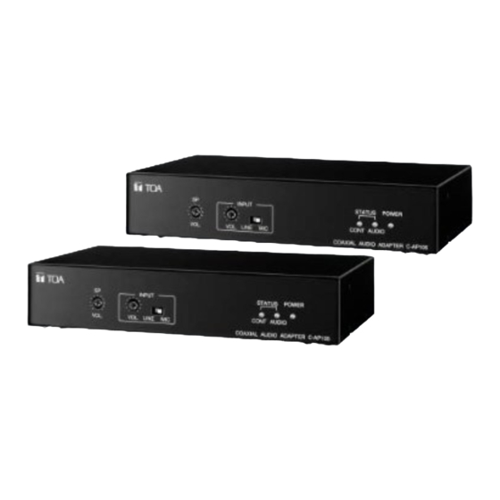
COAXIAL AUDIO ADAPTER
TABLE OF CONTENTS
1. SAFETY PRECAUTIONS .......................... 2
AND PARTS .............................................. 4
3. GENERAL DESCRIPTION ........................ 4
4. HANDLING PRECAUTIONS ..................... 4
Front Panel ................................................. 5
Rear Panel ................................................. 5
Microphone ................................................. 6
and stripped cable ends ................ 6
6.2. Cable Connections ............................... 6
7.1. Power Supply Connections .................. 7
Thank you for purchasing TOA's Coaxial Audio Adapter. Please carefully follow the instructions in this
manual in order to ensure long, trouble-free use of your equipment.
INSTRUCTION MANUAL
7.2. Audio Input Connections ...................... 7
7.3. Audio Output Connections ................... 8
7.4. Speaker Connections ........................... 8
and Output Connections ................ 8
7.6. AP Line Connections ............................ 9
7.7. Video Equipment Connections ............. 9
8.1. Rack-mounting units ............................. 9
8.2. Rack-mounting two units .................... 10
8.3. Wall Mounting ..................................... 10
8.4. Microphone Attachment ..................... 10
(TROUBLESHOOTING) ............. 11
10. SPECIFICATIONS .................................... 12
C-AP105
Advertisement
Table of Contents

Related Manuals for Toa C-AP105


Summary of Contents for Toa C-AP105
-
Page 1: Table Of Contents
7. CONNECTIONS (TROUBLESHOOTING) ..... 11 7.1. Power Supply Connections ....7 10. SPECIFICATIONS ........12 Thank you for purchasing TOA's Coaxial Audio Adapter. Please carefully follow the instructions in this manual in order to ensure long, trouble-free use of your equipment. -
Page 2: Safety Precautions
• Should the following irregularities be found during use, immediately switch off the power, disconnect the power supply plug from the AC outlet and contact your nearest TOA dealer. Do not attempt to further operate the unit to avoid fire or electric shock. - Page 3 Modifications Any modifications made to this device that are not approved by TOA Corporation may void the authority granted to the user by the FCC to operate this equipment.
-
Page 4: List Of Included Components And Parts
(C-A10MC), do not use the microphone during camera operation. • When using multiple C-AP105 units, be sure to only connect Unit A to Unit B. The system will not operate correctly if Unit A is connected to Unit A or Unit B is connected to Unit B. -
Page 5: Nomenclature And Functions Front Panel
5. NOMENCLATURE AND FUNCTIONS [Front Panel] INPUT STATUS POWER CONT AUDIO VOL. LINE MIC VOL. COAXIAL AUDIO ADAPTER C-AP100 (1) Power Indicator (4) Input Level Selector Lights (green) when the power is supplied to the Selects the input signal level. (MIC: -60 dB/LINE: -20 dB) unit. -
Page 6: Microphone
6.2. Cable Connections 1. Loosen the terminal screw to insert the cable into the connector, then retighten the screw. Tug lightly on C-AP105 rear panel the cable to be sure that it does not Tighten pull free. Connector 2. Insert the connector into the rear (Supplied with panel-mounted terminal. -
Page 7: Connections
7. CONNECTIONS 7.1. Power Supply Connections Connect to 12V DC (350 mA or more) Note: Make sure that the dc power supply is switched OFF during cable connection or disconnection. [If using an AC/ DC adapter] AC adapter Connect to DC IN 12V AC mains 7.2. -
Page 8: Audio Output Connections
[If using line signal level equipment] PHANT MIC/ LINE LINE OUT terminal of music play equipment 1. Connect the cable conductor to "Input" and shields to "C." 2. Set the front panel-mounted Input level selector switch to the LINE position. 3. -
Page 9: Ap Line Connections
8.1. Rack-mounting a single unit (using the optional MB-15B-BK mounting bracket set) 3 x 14 self-tapping screw * 3 x 14 self-tapping screw * C-AP105 Blank bracket * 3 x 14 self-tapping screw * IA L D IO... -
Page 10: Rack-Mounting Two Units
C-AP105 3 x 8 self tapping screw * 3 x 20 wall mounting screw * * Parts supplied with the C-AP105 unit. 8.4. Microphone Attachment [Mounting to a wall or ceiling] 1. Remove the microphone mounting screw (for the mounting plate) (17), and detach the microphone mounting plate. -
Page 11: If A Failure Is Detected
[Mounting to TOA cylindrical cameras] 1. Remove the microphone mounting screw (for the mounting plate) (17) and detach the microphone mounting plate. Note Removing the mounting screw (17) disassembles the microphone. Take care not to drop its parts and components. -
Page 12: Specifications
12V DC 350mA (cage clamp) Solid Wire : ø 0.4 - 1.2 mm (AWG26 - 16), Stranded Wire: 0.3 - 1.25mm (AWG22 - 16) AC/ DC adapter not supplied by TOA.* Power Consumption 3 W (standby), 8 W (maximum output)*...
Need help?
Do you have a question about the C-AP105 and is the answer not in the manual?
Questions and answers