
Subscribe to Our Youtube Channel
Related Manuals for Icom IC-M24


Summary of Contents for Icom IC-M24
-
Page 1: Instruction Manual
INSTRUCTION MANUAL VHF MARINE TRANSCEIVER iM24 This device complies with Part 15 of the FCC Rules. Operation is subject to the condition that this device does not cause harmful interference. -
Page 2: Foreword
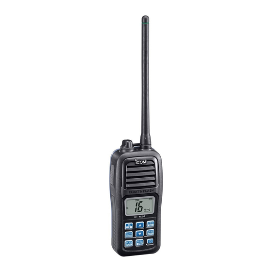
FOREWORD FEATURES ☞ Floats on water Thank you for purchasing this Icom radio. The IC-M24 is designed and built with Icom’s state of MARINE TRANSCEIVER The transceiver floats in fresh or salt the art technology and craftsmanship. With proper care this water even when the supplied acces- radio should provide you with years of trouble-free operation. -
Page 3: In Case Of Emergency
IN CASE OF EMERGENCY RECOMMENDATION If your vessel requires assistance, contact other vessels and CLEAN THE TRANSCEIVER THOROUGHLY WITH FRESH the Coast Guard by sending a distress call on Channel 16. WATER after exposure to saltwater, and dry it before operat- ing. -
Page 4: Safety Training Information
• ALWAYS keep the antenna at least 2.5 cm (1 inch) away from the body Electromagnetic Fields. when transmitting and only use the Icom belt clip which is listed on p. 28 when attaching the radio to your belt, etc., to ensure FCC RF exposure •... -
Page 5: Information En Matière De Sécurité
RF sans fil; attache pour ceinture (MB-124), bloc-piles rechargeable au lithium-ion (BP-266). Interférence électromagnétique et compatibilité En mode de transmission, votre radio Icom produit de l'énergie de RF qui CAUTION peut provoquer des interférences avec d'autres appareils ou systèmes. Pour Afin de vous assurer que votre exposition à... -
Page 6: Precautions
0.9 meters (3.0 ft) away from your vessel’s magnetic navigation compass. Icom, Icom Inc. and the Icom logo are registered trademarks of Icom Incor- porated (Japan) in Japan, the United States, the United Kingdom, Germany, France, Spain, Russia and/or other countries. -
Page 7: Table Of Contents
TABLE OF CONTENTS ■ Lock function ................13 FOREWORD ..................i ■ Monitor function ..............13 IMPORTANT ..................i ■ Automatic backlighting ............13 EXPLICIT DEFINITIONS ..............i ■ AquaQuake Water Draining function........13 FEATURES ..................i IN CASE OF EMERGENCY ............. ii RECOMMENDATION ............... ii 5 SCAN OPERATION ............14–15 ■... -
Page 8: Fcc Information
• Consult the dealer or an experienced radio/TV technician for help. CAUTION: Changes or modifi cations to this device, not expressly approved by Icom Inc., could void your authority to operate this device under FCC regulations. -
Page 9: Operating Rules
It is unlawful to operate a ship station which is not licensed, but required to be. NOTE: Even though the IC-M24 is capable of operation on VHF marine channels 3, 21, 23, 61, 64, 81, 82 and If required, contact your dealer or the appropriate govern- 83, according to FCC regulations these simplex channels ment agency for a Ship-Radiotelephone license application. -
Page 10: Supplied Accessories And Attachments
SUPPLIED ACCESSORIES AND ATTACHMENTS ■ Supplied accessories D Handstrap Charger Handstrap Battery pack Pass the handstrap through the loop on the back side of the transceiver as shown. D Belt clip Belt clip Flexible antenna Attach the belt clip to, or detach the belt clip from the transceiver. To attach the belt clip To detach the belt clip Lift the tab up (q), and slide... -
Page 11: Supplied Accessories And Attachments
SUPPLIED ACCESSORIES AND ATTACHMENTS D Battery pack NEVER remove the battery cover when the transceiver is wet or soiled. This may result in water or dust getting into To remove the battery pack: the transceiver/battery pack, and may result in the trans- Slide the latch and then lift the battery cover to remove it. -
Page 12: Panel Description
PANEL DESCRIPTION ■ Front, top and side panels q ANTENNA CONNECTOR (p. 2) Connect the supplied antenna here. w DC JACK [DC] (p. 23) Connect the charger or optional cable here. q To remove the [DC] jack cap, rotate it counter clockwise. - Page 13 PANEL DESCRIPTION t VOLUME/SQUELCH/MONITOR KEY [VOL/SQL MONI] u UP/DOWN KEYS [Y] or [Z] ➥ Push to enter the volume adjustment mode or the ➥ Push to select an operating channel. (pp. 8, 9) ➥ While in the Set mode, push to select the setting or squelch adjustment mode.
-
Page 14: Function Display
PANEL DESCRIPTION ■ Function display t CHARGE ICON (p. 23) Appears while charging. y BATTERY ICONS ➥ Displays the remaining battery capacity. Indication Charging Battery status Full Middle Exhausted required blinks when the battery is over charged. ➥ Scrolls while charging. (p. 23) u SCAN ICON (p. -
Page 15: Panel Description
PANEL DESCRIPTION !1 SUB CHANNEL READOUT !6 WEATHER CHANNEL/WEATHER ALERT ICONS (p. 9) ➥ Displays Channel 16 during a priority scan, Dualwatch ➥ “WX” appears when the weather channel group is se- or Tri-watch. (p. 16) lected. ➥ Displays the Set mode item while in the Set mode. (p. 17) ➥... -
Page 16: Basic Operation
BASIC OPERATION ■ Channel selection D Channel 9 (Call channel) IMPORTANT: Prior to using the transceiver for the first time, the battery pack must be fully charged for optimum Each regular channel group has a separate leisure-use Call life and operation (p. 23). To avoid damage to the trans- channel. -
Page 17: Weather Channels
BASIC OPERATION D USA, International and Canadian channels D Weather channels The transceiver is pre-programmed with 59 USA, 61 Inter- The transceiver has 10 weather channels. These are used national and 65 Canadian channels. Choose the appropriate for monitoring broadcasts from NOAA (National Oceanic and channel groups for your operating area. -
Page 18: Adjusting The Volume Level
BASIC OPERATION ■ Adjusting the volume level ■ Adjusting the squelch level The volume level can be adjusted using [VOL/SQL] and [Y] The squelch level can be adjusted using [VOL/SQL] and [Y] or [Z]. or [Z]. In order to properly receive signals, as well as for the scan q Push [VOL/SQL] once to enter the volume adjustment to effectively function, the squelch must be adjusted to the mode, then push [Y] or [Z] to adjust the volume level. -
Page 19: Receiving And Transmitting
BASIC OPERATION ■ Receiving and transmitting IMPORTANT: To maximize the readability of your trans- CAUTION: Transmitting without an antenna can damage mitted signal, pause for a second after pushing [PTT], the transceiver. hold the microphone 5 to 10 cm (2 to 4 inches) from your mouth and speak into the microphone at a normal voice q Hold down [ ] to turn ON the power. -
Page 20: Call Channel Programming
BASIC OPERATION ■ Call channel programming ■ Volume Loud function The Call channel is used to access Channel 9 (default). The Volume Loud function temporarily maximizes the vol- However, you can program the Call channel with your most ume level. often-used channel in each channel group, for quick recall. -
Page 21: Lock Function
BASIC OPERATION ■ Lock function ■ Automatic backlighting This function lights the function display and keys, and is con- This function electronically locks all keys (except for [PTT], [VOL/ venient for night-time operation. The automatic backlighting SQL], [MONI] (VOL/SQL), [ ] (Hi/Lo) and [Y] or [Z]*) to pre- can be activated in the Set mode. -
Page 22: Scan Operation
SCAN OPERATION ■ Scan types Set the TAG channels (scanned channels) before scanning. Scanning is an effi cient way to quickly locate signals over a wide frequency range. The transceiver has a priority scan Clear the TAG for unwanted channels which inconveniently and a normal scan. -
Page 23: Setting Tag Channels
SCAN OPERATION ■ Setting TAG channels ■ Starting a scan For more efficient scanning, add the desired channels as Set the Weather Alert function, Priority Scan function, Scan TAG channels, or clear the TAG on unwanted channels. Resume Timer and Auto Scan function in advance, in the Channels that are not tagged will be skipped while scan. -
Page 24: Dualwatch/Tri-Watch
DUALWATCH/TRI-WATCH ■ Description ■ Operation q Select Dualwatch or Tri-watch in the Set mode. (p. 19) Dualwatch monitors Channel 16 while you are receiving w Select the desired channel. on another channel; Tri-watch monitors Channel 16 and the e Hold down [DUAL] (SCAN) for 1 second to start Dual- Call channel while receiving another channel. -
Page 25: Set Mode
SET MODE ■ Set mode programming D Set mode operation The Set mode is used to change the settings of transceiver's q Turn OFF the power. functions: Beep Tone function, Weather Alert function, Prior- w While holding down [VOL/SQL], turn ON the power to ity Scan function, Scan resume timer, Auto Scan function, Dual/Tri-watch function, Monitor key action, Automatic back- enter the Set mode. -
Page 26: Set Mode Items
SET MODE ■ Set mode items D Priority Scan function D Beep Tone function “Pr” “bP” The transceiver has 2 scan types— normal (OFF) and pri- Turn the key touch beep sound ON or OFF. ority (ON) scan. A normal scan searches all TAG channels •... -
Page 27: Auto Scan Function
SET MODE D Auto Scan function D Monitor key action “AS” “Sq” The Auto Scan function automatically starts a normal or The monitor key temporarily opens the squelch. This item sets priority scan when no signal is received, and no operation is the key action. -
Page 28: Set Mode
SET MODE D Automatic backlighting D Power Save function “bL” “PS” This function is convenient for night-time operation. The The Power Save function reduces current drain by turning backlight can be selected from ON and OFF. OFF the receiver circuit for preset intervals. •... -
Page 29: Battery Charging
fi re. R DANGER! Use the battery only with the transceiver for which it is R DANGER! Use and charge only specifi ed Icom battery pack with specifi ed. Never use a battery with any other equipment, or for any Icom radios or Icom chargers. - Page 30 CAUTION: DO NOT charge the battery outside of the specified has been not used for a long period of time. The battery pack will temperature range: ±0˚C to +45˚C (+32˚F to +113˚F). Icom recom- have slowly self-discharged, even though it has not been used. If the mends charging the battery at +20˚C (+68˚F).
-
Page 31: Supplied Battery Charger
BATTERY CHARGING ■ Supplied battery charger ■ Optional battery charger D Charging Do not place the charger on a surface with any vibration. Otherwise the batter y pack might come out of the Do not use a charger other than the specifi ed one. charger, or the charger itself might fall. - Page 32 BATTERY CHARGING D AD-123 installation (continued) D Charging w Install the AD-123 into the holder space of the BC-119N • For BC-119N or BC-121N with the supplied screws as shown. The optional BC-119N provides rapid charging of the Li-ion battery pack. Charging time: Approximately 2.5 hours Screws supplied with The following items are additionally required:...
-
Page 33: Battery Charging
BATTERY CHARGING D Charging from a cigarette lighter socket • For BC-121N Use the optional CP-24 charge CIGARETTE LIGHTER CABLE from a cigarette lighter socket. The optional BC-121N allows up to six battery packs to be Charging time: Approximately 8.5 hours. charged simultaneously. -
Page 34: Troubleshooting
TROUBLESHOOTING PROBLEM POSSIBLE CAUSE SOLUTION REF. The transceiver does not turn • The battery is exhausted. • Recharge the battery pack. p. 23 • The battery pack is not correctly in- • Correctly insert the battery pack. p. 3 serted. No sound from speaker. -
Page 35: Vhf Marine Channel List
VHF MARINE CHANNEL LIST Channel number Frequency (MHz) Channel number Frequency (MHz) Channel number Frequency (MHz) Channel number Frequency (MHz) CAN Transmit Receive CAN Transmit Receive CAN Transmit Receive CAN Transmit Receive 156.050 160.650 157.050 161.650 156.425 156.425 157.325 157.325 156.050 156.050 21A 157.050 157.050 156.475 156.475... -
Page 36: Specifications And Options
Icom transceiver. Icom is not responsible for the destruction or • Intermodulation : 70 dB typical damage to an Icom transceiver in the event the Icom transceiver is used with • Spurious response : 70 dB typical equipment that is not manufactured or approved by Icom. - Page 37 MEMO...
- Page 38 MEMO...
- Page 39 MEMO...
- Page 40 A-6911H-1EX-w Printed in Japan 2011 Icom Inc. © 1-1-32 Kamiminami, Hirano-ku, Osaka 547-0003, Japan Printed on recycled paper with soy ink.
Need help?
Do you have a question about the IC-M24 and is the answer not in the manual?
Questions and answers