Table of Contents
Advertisement
Quick Links
Download this manual
See also:
Service Manual
Advertisement
Table of Contents

Related Manuals for Icom IC-M21


Summary of Contents for Icom IC-M21
- Page 1 INSTRUCTION MANUAL VHF MARINE TRANSCEIVER iM21...
-
Page 2: In Case Of Emergency
IN CASE OF EMERGENCY RECOMMENDATION If your vessel requires assistance, contact other vessels and CLEAN THE TRANSCEIVER THOROUGHLY WITH FRESH the Coast Guard by sending a distress call on Channel 16. WATER after exposure to salt water. ❍ USING CHANNEL 16 Otherwise, the transceiver’s keys, switches and controllers may become inoperable due to salt crystallization. -
Page 3: Foreword
FOREWORD FEATURES Water resistant construction Thank you for purchasing this Icom product. The IC-M21 VHF MARINE TRANSCEIVER is designed and built with Icom’s su- Built tough to withstand the punishing marine environ- perior technology and craftsmanship. With proper care this ment, the IC-M21 meets JIS water resistant specification... -
Page 4: Cautions
AVOID using or placing the transceiver in direct sunlight or in areas with temperatures below –15°C or above +55°C. Versions of the IC-M21 which display the “CE” symbol on the serial number seal, comply with KEEP the transceiver out of the reach of children. -
Page 5: Table Of Contents
TABLE OF CONTENTS IN CASE OF EMERGENCY ..........i 5 SCAN OPERATION ..........11–12 I Scan types ..............11 RECOMMENDATION ............i I Setting tag channels ..........12 FOREWORD ............... ii I Starting a scan ............12 IMPORTANT ................ ii EXPLICIT DEFINITIONS ............. -
Page 6: Operating Rules
OPERATING RULES D Priorities (2) OPERATOR’S LICENSE A restricted Radiotelephone Operator Permit is the license • Read all rules and regulations pertaining to priorities and most often held by small vessel radio operators when a radio keep an up-to-date copy handy. Safety and distress calls is not required for safety purposes. -
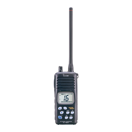
Page 7: Panel Description
PANEL DESCRIPTION I Front, top and side panels q DIAL /CHANNEL GROUP SWITCH [DIAL] t TRANSMIT POWER/LOCK SWITCH • Selects and changes the regular channels. [H/L• LOCK (p. 6) • Selects high, middle or low power when • Selects one of 2 regular channels in se- pushed. - Page 8 If the seal is damaged, water resistant is not guaranteed. To attach the battery case: Insert the battery case in the IC-M21 completely, then turn the screw clockwise. NOTE: When attaching a battery pack/case, make sure dust etc.
-
Page 9: I Function Display
PANEL DESCRIPTION I Function display q TRANSMIT INDICATOR (p. 8) Appears while transmitting. w BUSY INDICATOR (p. 8) Appears when receiving a signal or when the squelch opens. e TAG CHANNEL INDICATOR (p. 12) Appears when a tag channel is selected. r SCAN INDICATOR (p. -
Page 10: Panel Description
PANEL DESCRIPTION o SUB CHANNEL READOUT !5 TRANSMIT POWER INDICATOR • Indicates Channel 16 during priority scan. • “LOW” appears when low power is selected. (p. 8) • Indicates Channel 16 during dualwatch or tri-watch. • “LOW” blinks when switching forced low power mode be- (p. -
Page 11: Basic Operation
BASIC OPERATION I Channel selection D International and U.S.A. channels D Channel 16 There are 57 International and 57 U.S.A. channels. These Channel 16 is the distress channel. It is used for establishing channel groups may be specified for the operating area. initial contact with another station and for emergency communications. -
Page 12: I Lock Function
BASIC OPERATION I Lock function I Adjusting the squelch level This function electronically locks all keys, except [PTT], The IC-M21 has a squelch even though there is no control [SQL• ] and [H/L• ] to prevent accidental channel knob for it. In order to receive signals properly, as well as for... -
Page 13: I Receiving And Transmitting
BASIC OPERATION I Receiving and transmitting IMPORTANT: To maximize the readability of your trans- mitted signal, pause a few sec. after pushing [PTT], hold the microphone 5 to 10 cm (2 to 4 inches) from your CAUTION: Transmitting without an antenna may mouth and speak at a normal voice level. -
Page 14: I Call Channel Programming
BASIC OPERATION I Call channel programming r Push [Y]/[Z] to select the de- The call channel switch is used to select Channel 9 by de- fault, however, you can program your most often-used chan- sired channel. nels in each channel group for quick recall. q Push [DIAL] for 1 sec. -
Page 15: Dualwatch/Tri-Watch
DUALWATCH/TRI-WATCH I Description I Operation q Select the desired operating channel. Dualwatch monitors Channel 16 while you are receiving an- w Push [DW• other channel; tri-watch monitors Channel 16 and the call ] momentarily to start dualwatch; push channel while receiving another channel. [DW•... -
Page 16: Scan Operation
SCAN OPERATION I Scan types Scanning is an efficient way to locate signals quickly over a Set the tag channels (channels to be scanned) before scan- wide frequency range. The transceiver has a priority scan and ning. Clear the tag channels which inconveniently stop scan- a normal scan. -
Page 17: I Setting Tag Channels
SCAN OPERATION I Setting tag channels I Starting a scan For more efficient scanning, add desired channels as tag Set scan type and scan resume timer in advance using SET channels or clear tag channels for unwanted channels. Chan- mode. (pgs. 13, 14) nels set as non-tag channels will be skipped during scanning. -
Page 18: Set Mode
SET MODE I SET mode programming I SET mode items D Beep tone “bP” SET mode is used to change the conditions of 11 transceiver You can select silent operation by turning beep tones OFF or functions: beep tone, scan type, scan resure timer, auto scan, you can have confirmation beeps sound at the push of a monitor action, automatic backlighting, LCD contrast, auto switch by turning beep tones ON. - Page 19 SET MODE D Scan resume timer D Monitor action selection “St” “Sq” The scan resume timer can be selected as a pause (OFF) or The monitor function cuts off the squelch function temporarily. timer scan (ON). When OFF is selected, the scan pauses This selection contains PUSH or HOLD settings as shown until a received signal disappears.
- Page 20 SET MODE D LCD contrast selection D Self check function “LC” “SC” The contrast of the LCD can be adjusted from 4 levels. The self check function checks transceiver conditions by it- self, and informs you in case a problem is found. The follow- •...
-
Page 21: Set Mode
SET MODE D Battery voltage indicator “bt” This function contains display or non-display settings of the SET MODE LIST voltage of the connected battery pack when the power is ON. Function Indication Switch • The voltage of the connected battery pack is displayed for 2 sec. after power is turned ON. -
Page 22: Battery Charging
BATTERY CHARGING I Battery charging I Battery cautions Prior to using the transceiver for the first time, the Ni-Cd bat- NEVER incinerate used Ni-Cd batteries. Internal battery gas teries must be fully charged for optimum life and operation. may cause an explosion. CAUTION: To avoid damage to the transceiver, turn it OFF NEVER immerse batteries in water. -
Page 23: I Installing Batteries In The Battery Case
BP-224 • Keep battery contacts clean. It’s a good idea to clean bat- tery terminals once a week. Charge indicator Lights green when BP-224 (with/without IC-M21) is inserted. Supplied screws AC adapter (BC-147E; Not BC-150 supplied with some versions) -
Page 24: I Optional Battery Chargers
• AD-103 quired. • An AC adapter (may be supplied with BC-119N depending • Six AD-103. on version). • An AC adapter (BC-124) or the DC power cable (OPC-656). IC-M21 IC-M21 BP-224 BP-224 AD-103 charger adapters are installed AC adapter in each slot. -
Page 25: Supplied Accessories And Attachments
SUPPLIED ACCESSORIES AND ATTACHMENTS Supplied accessories Flexible antenna The following accessories are supplied: Qty. Connect the supplied flexible antenna to the antenna con- q Flexible antenna ....... .1 nector. -
Page 26: Swivel Belt Clip
SUPPLIED ACCESSORIES AND ATTACHMENTS D Swivel belt clip To attach: q Slide the stopper into the plastic loop on the back of the e Insert the stopper to the back of the belt clip. transceiver. w Clip the belt clip to a part of your belt. Once the transceiver is locked in place, it will swivel 360 de- grees. -
Page 27: Supplied Accessories And Attachments
SUPPLIED ACCESSORIES AND ATTACHMENTS To remove: q Turn the transceiver upside down, and then lift to release R R CAUTION! the transceiver from the belt clip. HOLD THE TRANSCEIVER TIGHTLY, WHEN ATTACH- ING OR REMOVING THE TRANSCEIVER FROM THE BELT CLIP. If the transceiver is accidentally dropped and the swivel belt clip’s stopper is scratched or damaged, the swivel belt clip may not work properly. -
Page 28: Troubleshooting
TROUBLESHOOTING PROBLEM POSSIBLE CAUSE SOLUTION. REF. • The battery is exhausted. • Recharge the battery pack. No power comes ON. p. 17 • Bad connection to the battery pack. • Check the connection to the transceiver. p. 3 • Squelch level is too deep. •... -
Page 29: Channel List
CHANNEL LIST International channels Frequency (MHz) Frequency (MHz) Frequency (MHz) Frequency (MHz) Frequency (MHz) Frequency (MHz) Transmit Receive Transmit Receive Transmit Receive Transmit Receive Transmit Receive Transmit Receive 156.050 160.650 156.550 156.550 157.050 161.650 156.125 160.725 156.625 156.625 157.125 161.725 156.100 160.700 156.600... -
Page 30: Specifications And Options
SPECIFICATIONS AND OPTIONS I Specifications I Options • GENERAL D BATTERY CASE AND PACK Frequency coverage : Transmit 156.000–161.450 MHz • BP-223 BATTERY CASE Receive 156.000–163.425 MHz Battery case for 6 × AA (R6) alkaline cells. The same as supplied Mode : FM (16K0G3E) with the transceiver depending on versions. -
Page 31: Declaration Of Conformity
DECLARATION OF CONFORMITY 0560 We Icom Inc. Japan 1-1-32 Kamiminami, Hirano-ku, Osaka 547-0003 Japan Declare on our sole responsibility that this equipment complies with the essential requirements of the Radio and Telecommunications Terminal Equipment Directive, 1999/5/EC, and that any applicable Essential Test Suite measurements have been performed. - Page 32 Count on us! < Intended Country of Use > A-6117H-1EU Printed in Japan © 2001 Icom Inc. 1-1-32 Kamiminami, Hirano-ku, Osaka 547-0002 Japan...
Need help?
Do you have a question about the IC-M21 and is the answer not in the manual?
Questions and answers