
Related Manuals for Ikegami IPD-Q38


Summary of Contents for Ikegami IPD-Q38
- Page 1 INSTRUCTION MANUAL High Performance (APPLICATION INSTRUCTIONS) Day/Night IP PTZ Camera IPD-Q38 Carefully read this manual before use in order to keep these products at full capacity.
-
Page 2: Table Of Contents
Table of Contents PREFACE ..........................1 MAKING CONNECTIONS....................... 4 PC.......................... 4 ONNECT TO ..................6 ONNECTION WITH NTERNET XPLORER MAKING BASIC SETTINGS ....................8 ......................8 CREEN ONFIGURATION ........................ 10 ETTING ROCEDURE ........................12 HELP F UNCTION ........................13 ETTING ETWORK .......................... - Page 3 EBOOT THE SYSTEM ..................95 ISPLAYING THE CURRENT CONDITION ..................97 ISPLAYING THE MACHINE INFORMATION TROUBLESHOOTING ......................98 GLOSSARY ........................... 101 INDEX ........................... 106 SPECIFICATIONS........................ 109 IPD-Q38 ............. 109 IP PTZ C ERFORMANCE IGHT AMERA DRAWINGS ..........................112 IPD-Q38..........................112 - 2 -...
-
Page 4: Preface
Preface Features Thank you for choosing this Ikegami High Performance PTZ Speed Dome IP Camera. Please read the Instruction Manual (Setup Instructions) for the full setup procedure, before reading this application manual, as this manual describes further procedures and operations in more depth than the basic setup procedure manual. - Page 5 Automatic Pre-set Tour function for convenient tour for pre-set points. Smart motion detection function with multi-parameter algorithm. It is called as an Ikegami Intelligent Low False Alarm Motion Detection (Patent pending). Well designed and accurate Alarm function with low false alarm rate with Pre and Post alarming.
- Page 6 Terminology In this instruction manual, “Left-click” is used to mean “click the left mouse button”. and “Right-click” means click the right mouse button. Also in this manual, “Left drag” or “Drag” is used to mean “hold down the left mouse button and move the mouse” and “Right-drag”...
-
Page 7: Making Connections
Making connections Before making connection, IP address and Internet Explorer Setup of the PC must be changed to make it identical with the PTZ camera. The PC has to be separated from a network while doing this procedure. To begin, connect this PTZ camera and the PC with a direct LAN cross over cable, or via a HUB/SWITCH to change the units IP address from the default factory IP setting. - Page 8 Connection through HUB/SWITCH This shows how to connect the PTZ camera through a HUB/SWITCH. Please be sure to use a straight LAN cable of Cat-5 (Category5) or better. This camera (Pendant type) Initial setting IP address :192.168.1.100 Subnet mask :255.255.255.0 PC (Windows XP) IP address :192.168.1.***...
-
Page 9: Connection With Internet Explorer
Connection with Internet Explorer To connect using Internet Explorer, first input the of this PTZ camera. The initial setting of the machine is “http://192.168.1.100”. You are asked for an user name and a password after the pop-up window opens. Then, input the administrator’s or operator’s name and click An operator’s name is not registered in an initial setting. - Page 10 Installation of the ActiveX picture display Video images or pictures will not be displayed on a screen before installing the ActiveX to the PC. The screen below shows the Windows XP Service Pack 2. The screen is different with the Windows XP Service Pack1 or earlier versions. Click the yellow bar on the upper side of a screen and install ActiveX.
-
Page 11: Making Basic Settings
Making Basic Settings Before installing the camera, ensure that the basic setup is completed. It is necessary to log onto the camera as the administrator in order to change the basic camera settings. The default administrator’s user name is “admin”, and the default password is “1”. To change the setup, select “SETTING”... -
Page 12: Setup Menu
Sections of description dealing with SETTING Mode Making Basic Settings (p.8) Monitoring Audio, Listening and Sending (p.31) Operation Use Auto-Pan (p.40) Use Pre Set Tour (p.43) Using alarm function (p.50) Other functions (p.70) ② Setup Menu For a selection of setup items (p.13) Setting Network (p.15) -
Page 13: Setting Procedure
Setting Procedure Click an item to change on the setup menu. The Setup screen shows up on the right side of the screen, then, input the desired parameters for change and click Click if you want to go back to the value when started. The confirmation dialogue box shows up. - Page 14 Setting input is displayed and the new setting is OK and saved, when the message of “Setting succeeded” appears. “Motion Detection”(p.53) will remain even without clicking and the screen shows the result, but these will return to the previous setting (the last saved setting), when the PTZ camera is restarted.
-
Page 15: Help Function
HELP Function Useful clues or suggestions will appear on the screen when you use HELP for values to input, or hints for the entry column. To get HELP, select HELP ON at the top right-hand corner of the screen. A desired HELP will be displayed when you check the area on the entry column or the input area with the mouse. -
Page 16: Setting Network
Setting Network Network setting is needed when connecting this PTZ camera to a LAN, WAN or the internet. Internet setting is made with the IPv4 setup screen. To set this, select and click IPv4 in the Setting Menu. ① ② ③... -
Page 17: Time Setting
⑥ MTU Make a setting. The numbers to input should be between 576 to 1500. The initial setting is “1454”. ⑦ DNS Server Make the IP address setting for Server. No need to specify an alternative DNS Server. The initial setting is “192.168.1.1” for the priority Server. Alternative DNS Server is not specified. -
Page 18: To Change The Registration Of Administrator
To change the Registration of Administrator The settings can be changed to a unique administrator’s name. The initial default settings are “admin” for user’s name of administrator and “1” for the password. It is recommended to change those settings as soon as the installation is made, for a protection from malicious or accidental attempts to change the setup. -
Page 19: Registration Of Operator
Registration of Operator Registered operators can observe pictures on a screen (monitoring) and can control camera movement (camera operation). However they can not change settings nor perform any maintenance operations. For normal surveillance applications, the operator’s control is adequate and is recommended. -
Page 20: Change Camera Settings
⑤ Action No change : Un-change the settings of this operator. Register : Make effective the changes that this operator did. Delete : Erase those settings made by this operator. Change Camera Settings There are two ways to change and adjust the camera settings. One is via the “Camera Setting”(p.17), and the other way is via... - Page 21 a maximum of 32 times sensitivity increase is possible electronically. ③ Shutter Speed This is used to select the shutter speed control either Manual or Automatic. When the Auto is required, set it OFF position. With Manual control, you can choose in 1 to 100th a second up to 1 to 10,000th a second this enables pictures to be recorded of fast moving object so that on playback a steady still picture is displayed without blurring or picture pixel jump.
- Page 22 ⑦ Day/Night This is used to select either fixed Monochrome (black and white) pictures, fixed Color pictures or full Auto pictures. AUTO makes automatic change-over for color in day time or when sufficient Light is available, and for monochrome at night or low light conditions.
-
Page 23: Setting The In/Out Terminal Connection
Setting the In/Out Terminal connection This is to set IN 1 or IN 2, OUT 1 or OUT 2 with the terminal contact. The standard configuration for the Flush mount type is; AUDIO, MIC, OUT 1, IN 1. The standard configuration for the Pendant type is; AUDIO, MIC, IN 1. As a factory activated option all the following can be provided;... - Page 24 ④ OUTPUT 1 (for Pendant type it is a factory activated option) This provides an output with selected functions to external devices. ⑤ OUTPUT 2 (Factory option) This is the same as OUTPUT1 but is a factory activated option. Function Description 1...
-
Page 25: Installation
Installation After completion of the Basic Setting, the PTZ camera is ready to be deployed to its working position. This chapter describes an example with a simulated IP address and Subnet mask (you are reminded to use a configuration provided by the Network Administrator when you actually install the camera). - Page 26 Over different networks This is an example of how to install the PTZ camera into a different network from the PC. In this case, the connection has to be made through a HUB/SWITCH or other tools to connect those two networking. Check and set the IP address, the Subnet Mask, and Gateway’s IP address properly to the parameters provided by the Network Administrator.
-
Page 27: Installation Over Internet
Installation over Internet This is an example of how to install the PTZ camera in a different place from PC, over the Internet. In some cases, the video may not show up depending upon the settings of the proxy server to be used. In this instance please check, re-adjust and re-set the setting of the proxy server. - Page 28 This camera (Pendant type) IP address :192.168.1.100 Subnet mask :255.255.255.0 Gateway :192.168.1.1 HTTP port :80 Router HTTPS port :443 LAN side IP address:192.168.1.1 Modem, etc. WAN side Port forward setting port 80 → port 80 of 192.168.1.100 port 443 → port 443 of 192.168.1.100 In case of fixed IP address IP address :...
- Page 29 Allocate Global IP Address When the global IP address is allocated, not only the Router, but also for the PTZ camera, it is not necessary to set up Port Forward. Take necessary steps to go direct and set the firewall. This camera (Pendant type)...
-
Page 30: Monitoring
Monitoring After all those settings are complete you make the PTZ camera connection from a PC, you can now watch video images on a screen. Screen Configuration ① ② ④ ③ ① Mode Selection For operation of monitoring and camera, select MONITOR from Mode. If this is selected, the screen changes and the camera menu and streaming video are displayed. - Page 31 It is in the fixed mode if the operation is made starting with Operator’s name this function is inactive. ② Menu Selection This is to change the Menu ③ among those four, “DELIVERY CONTROL” (p.32), ”CAMERA CONTROL”(p.33), “CAMERA FUNCTION”(p.19) and “PRESET” (p.38).
-
Page 32: Viewing Pictures
Viewing Pictures Screen Video Title, if any Time Display mark while recording Status Message display There are 4 kinds of messages on Status message. Pre-Alarm : This shows the Pre-Alarm recording is ON and active. Alarm Data Exists : This shows the alarm recording is in progress. Alarm Detected : This will appear when alarm condition is started. - Page 33 ② Information To be used to change the display positions of “TITLE”, “TIME” and “STATUS” those are overlapped on a screen. Select 1: the title and date/time are displayed at the top of the screen and status at the bottom. Select 2: the status is displayed at the top of the screen and the title and date/time at the bottom of the screen.
-
Page 34: Audio, Listening And Sending
Audio, Listening and Sending Select Mic On with the System Setting Screen when sending and distributing an Audio signal. Click System on the Setting Menu. Use following Icon to listen or to send Audio. DirectX should be installed to listen to Audio via the PC. ①... -
Page 35: Controlling Streaming Video
Controlling streaming video The streaming video can be controlled with the “DELIVERY CONTROL” menu at the bottom left of the screen. The Menus are different in the Administrator screen and Operator screen. When changing the default settings for RESOLUTION, PICTURE QUALITY and FRAME RATE, change the settings for “Default Delivery Control”(p.78) in System... -
Page 36: Operation
Operation To operate a camera, go to the Monitor screen and select the CAMERA MENU. Choose one of the following: “DELIVERY CONTROL”, “CAMERA CONTROL”, “CAMERA FUNCTION” and “PRESET” from the drop down list. Controlling the camera Direction, Zoom and Focus There are two ways to control the PTZ camera for Direction, Zoom and Focus. - Page 37 ① PAN-TILT This is for moving the directions of PTZ camera, while pressing. If the movement does not stop, click the mark in the centre, this will then stop the motion. When multiple instructions are coming in almost simultaneously, the last instruction coming in has priority.
- Page 38 To use One Click Scope The “One Click Scope” can make to move the pointed object to the screen centre. And a zoom control can be made by a mouse wheel after making centering. Click here, for instance The pointed object moves quickly to the centre of the screen.
- Page 39 Operating with Normal Mode This normal mode is to control the camera with screen by pointing. Put the cursor of the Mouse on the screen, the Cursor Icon changes to the . The direction of the arrow marks are eight (8) as shown as below. The cursor Icon changes to the when moving the mouse cursor to the centre.
- Page 40 Changing Speed To change speed of panning/tilting or lens control, go to the “CAMERA CONTROL” menu in "MONITOR" mode. ① ② ① PAN-TILT VELOCITY This is to select desired velocity of Pan and Tilt movement in LOW, MIDDLE, HIGH or AUTO. In the “AUTO” mode, it selects the optimum velocity for the zoom ratio.
-
Page 41: Preset Functions
Preset Functions The preset function enables the camera to store and recall PTZ positions, without the need to use the manual Pan, Tilt, Zoom and Focus controls. There are two ways to use this preset function, one is the “Preset Procedure with the “CAMERA CONTROL” menu”... - Page 42 IN 2 terminal is a factory option but can provide the same function as IN 1. For details please refer to the dealer or distributor or Ikegami directly. ※ When the IPD-Q38 has been customized with the factory activated option, there may be two terminals IN 1 and IN 2 available. If signals come almost simultaneously into both the IN 1 and IN 2 terminals, the function of the second incoming signal's terminal is executed.
-
Page 43: Use Auto-Pan
Use Auto-Pan To make the Auto Pan active, the panning range can be programmed. Program Auto Pan range Go to the "PRESET" menu (p.38) in the "MONITOR" mode Screen. Enter the panning start point at No.98 preset number and the turn over point at No.99 preset number. - Page 44 Then, the camera starts to make Auto Panning. Click again , it stops. Present position Auto-pan start position Click Auto Pan ON, it goes to No.98 position with its fastest speed When Auto Pan starts to work, the camera quickly goes to the Auto Pan starting position which is the Preset position No.98 and panning starts counter-clockwise (looking up from below) and it goes back at the turn over point, which is the preset position No.99.
- Page 45 Figure from below Pan to left ① ② Pan to right Auto-pan start position Auto-pan return position (Position of preset number 98) The Auto Pan velocity is the programmed velocity of the Pan and Tilt Control and the velocity can not be controlled while Auto Pan is active. The tilt controls for Up and down, also for Zoom In and Out can be controlled manually.
-
Page 46: Use Pre Set Tour
Use Pre Set Tour A preset tour makes the camera move, continuously panning and tilting to visit preset positions in a selected sequence of running, dwelling and move again in preset timing and velocity. This makes surveillance work easy and effective. The Pre-set tour function is to make the camera have a tour for the pre-set positions as programmed. - Page 47 The registered data is displayed when you select the Preset Tour pattern number, if Preset Tour pattern is saved. If the pattern is not registered, only a blank line is displayed. Pattern selection To register preset in Preset Tour pattern, use the “Select” box on the right side of the Preset List.
- Page 48 ・Preset This is to select a preset for registration. It is shown on the display list of registered presets for selection. Selecting a preset and clicking causes the camera to move to that preset position. ・Dwell Time This is to program the dwell time of a preset tour or the amount of time the camera will stay at a preset during a preset tour.
- Page 49 After selecting these, the input data will be displayed on the preset list at. The lower left corner by clicking , (this stands for registration). Repeat this procedure to make a Preset Tour program. After making the Preset Tour program, it must be saved. Even when making the lists of the preset tour, the information not transferred to save in the PTZ camera.
- Page 50 To check the registered Preset Tour Program, click next to Pattern Numbers, but this is just to check and confirmation the input information. To activate the Preset Tour, use “Tour” in the “CAMERA CONTROL” menu of the "MONITOR" mode. Preset Tour...
- Page 51 Preset Tour with the “CAMERA CONTROL” menu Go to the “CAMERA CONTROL” menu in "MONITOR" mode, and choose the desired preset tour pattern number and click . The Preset Tour will start. Pushing , halts the Tour. As an example, if the following preset tour is programmed, the camera moves with fastest velocity to the tour starting position (Pos.1) then, after starting the tour, the camera visit the position1 and dwells 5 seconds and moves in high velocity to the position 2.
- Page 52 IN 2 terminal is a factory option but can provide the same function as IN 1. For details please refer to the dealer or distributor or Ikegami directly. ※When the IPD-Q38 has been customized with the factory activated option, there may be two terminals IN 1 and IN 2 available. If signals come almost simultaneously into both the IN 1 and IN 2 terminals, the function of the second incoming signal's terminal is executed.
-
Page 53: Using Alarm Function
Using alarm function This chapter describes the Alarm Function, pre and post alarm video images can be recorded for a few seconds directly on the PTZ camera and if required, information of the alarm situation can be sent via PC mail to other terminals or to Cellular phones. To set the alarm function The alarm function should be ON, when you want to use the alarm function. -
Page 54: Record Alarm Pictures To The Built-In Memory
⑤ Picture Protection When the built-in memory of the PTZ camera becomes full, it will stop recording new pictures. Then, you have to decide to allow an over-write, or disable an over-write. If there is available space in the built-in memory, after sending data for down loading to other places such as a PC, the built-in memory in the PTZ camera starts recording of alarm pictures. - Page 55 Recording Time of Alarm Picture Recording of the alarm picture in the built-in memory can only be done with Picture Quality A grade and 1 to 1 resolution. You can not change these settings. The recording time depends on type of input signal, NTSC or PAL, and the number of pictures you save.
-
Page 56: Motion Detection
Motion Detection When the motion detection function is enabled, alarm signals can be generated, when something is moving within the camera view. Both the alarm function (p.50) and the motion detector have to be enabled to use the motion detection function. You can have Motion Detection Setting screen on the right side of the screen when clicking the “Motion Detection”... - Page 57 ④ Sensitivity This is to program the level of motion detection. Higher sensitivity setting means Motion is easily detected, but it may respond to small movement of tree leaves. The optimum sensitivity setting is normally somewhere between 10 and 20. Some adjustment will be required to find the best position with consideration of the scene being viewed on the screen.
- Page 58 Mask Setting To set masking area, click “MASK” and the masked area, which does not respond to the motion detection, will be shown in blue color by left-clicking or left dragging. All the movement within this blue area will not be reported as motion detection. Left drag.
- Page 59 Minimum Size Setting To program a minimum detection size, left click or left-drag on the screen to set a size. The recommended size setting is to have about two third in length and breadth if an object is human. The minimum size setting helps to avoid false alarms as it becomes less sensitive to a smaller thing such as animal, or a person standing far behind the object, those being televised in smaller size than the detection size.
- Page 60 To check Motion Detection You can see the out break of alarm condition on the screen, when it happens while Alarm and Motion Detection are set ON. Motion Detection Frame Alarm recording ON indication, displaying Alarm Data Exists. Motion Detection Frame The frame is displayed around the moving object, when it detects motion.
-
Page 61: Send Alarm By Mail
Send alarm by mail It is possible by e-mail to inform of generation of an alarm. Internet Alarm Sending alarm notice on e-mail when an alarm incident occurs You can notify an alarm condition via e-mail. To use this function, the setting for an alarm e-mail needs to be done. - Page 62 ③ SMTP Server : Input an IP address or a host name of SMTP server. Port : Input a port number of SMTP server of the server. ④ Use Authentication This is to select the way of authentication or approval. :...
-
Page 63: Sending Alarm Signal To External Devices From The Out Terminal
Sending Alarm signal to external devices from the OUT terminal You have to make setting referring to IN/OUT Setting (p.20) to send alarm signals to external devices from the OUT terminal. This has to be made to set various alarm functions such as All Alarm, Terminal 1 Alarm, Terminal 2 Alarm or Motion Detection. - Page 64 ■ Connection Example 2 Preset on the IN 1 (p.20) connected with external device such In case of setting the as sensors, and make “Point Alarm1” setting on OUT 1 and make connection to an external device such as Buzzer. ②...
-
Page 65: Recording And Play Back
Recording and Play Back You can record alarm video or streaming video into the built-in memory of the PTZ camera. There are two ways to record video. By down loading the recorded video in the built-in memory into the PC. By recording the streaming video on the PC into the PC memory. -
Page 66: To Record Streaming Video In Pc
To record Streaming Video in PC In addition to the downloading of the alarm video recorded in the PTZ camera, you can record the streaming live video displayed on a screen with Browser into the PC. In this case, the resolution, the picture quality and the frame rate are the same as the delivery picture to PC. -
Page 67: Take A Still Picture
Non Stop Continue to record until you click “STOP” recording in the DELIVERY CONTROL Menu. In this Non Stop mode, a new “DATE/TIME” folder is created in every 10 minutes and recorded in the folder as “Desktop/Monitoring/StreamingTitle/ Record/Date/Time”. If there is no streaming title, “Desktop/Monitoring/Record/Date/Time” is the default position. -
Page 68: Playback
Playback You can play back the down loaded alarm video, or recorded streaming video in PC. Resolution, Picture Quality and Frame rate in Play back The resolution, picture quality and frame rate in play back are as follows, Alarm video quality down loading from the PTZ camera, Resolution :... - Page 69 The type of videos are as follows Alarm : Down loaded video by the alarm data streaming. Auto-Alarm : Recorded video by the Auto Alarm Recording. Record : Recorded video by the Record. For example, the following shows the selected folder of the recorded video on March 2007 at 11 hours 43 minutes, 28.767 seconds.
- Page 70 To play back recorded video, open the HTML file with Internet Explorer. The upper screen of Internet Explorer may show a yellow bar saying “To help protect your security, Internet Explorer has restricted this file from showing active content that could access your computer, Click here for option…”. In this case click the bar. A Menu opens, click on “Allow Blocked Content”.
- Page 71 The play back starts when you click Operation of the play back screen ② ① ① Operation buttons From left side, there are those buttons. :Pause :Fast Rewind (Every click changes speed at 2 times, 5 times, 10 times, 2 times and so on.) :Reverse play :Stop...
- Page 72 ② The Recorded Video The display video is the same as streaming video on the monitor screen. In the streaming video screen, the operation status is displayed at the position to show “REC” on the let upper side of the screen. In the streaming video screen, the operation status is displayed at the position to show “REC”...
-
Page 73: Other Functions
Other functions Registration of a Network Recorder To record on a Network Recorder the Password and Log In Name of the recorder have to be registered. ① ② ③ ④ ① Login Name Input the Network Recorder’s login name. Up to 16 alphanumeric characters can be used. -
Page 74: Automatic Adjustment Of A Time Difference
Automatic adjustment of a time difference Using the function, a time difference can be adjusted automatically. To do this, click “NTP” in the Setting Menu. ① ② ③ ④ ① Use NTP Select this to ON, the time is automatically adjusted with NTP. ②... -
Page 75: Privacy Masking, Hiding A Part Of Screen
Privacy Masking, Hiding a part of screen The privacy mask function acts to make a part of streamed video un-visible so that an operator can not view the scene where the PTZ camera is positioned. To set this, click "Privacy Mask" in the Setting Menu. Privacy Mask Function The privacy mask is active on the alarm video... - Page 76 Creating Masking Zones To create Masking Zones, move the PTZ camera by pan and tilt control or by using the “One Click Scope” function (p.35) on a screen to the desired position. Please note that the tilting range is limited within a range of 0 degree to 90 degree (Directly underneath) when the dynamic range is ON (p.17, “Change Camera Settings”).
- Page 77 Click of the “Select” column in the Mask Setting window. Please note that temporarily the Pan and Tilt control become enabled when clicking . It will move to the position of tilting angle of 45 degrees automatically, if the setting was made more than an angle of 45 degrees of tilt. The masking area can be created when half transparent white area appears on the screen.
- Page 78 When in the process of creating of privacy masking zones, the dialogue box appears then, click to have privacy zones. Ensure you tick off the Function column of the dialogue box so that the created masking zones appear on a screen. The tilt angle is restricted between 0 and 90 degrees, when this Function is ON.
- Page 79 Delete Masking To take off the mask setting, choose the desired mask number in the table and tick the number in the select column. then click Translucent white area in the screen The control for Pan and Tilt becomes enabled, when a semi-transparency white area is seen on the screen.
-
Page 80: To Change The Tv Standard
To change the TV Standard To change the TV scanning standard to either NTSC, or PAL, with the “System Setting” screen. Click “System” in the System Setting Menu. ① ① Compressed Picture Select the picture scan mode. Frame In this mode, the frame picture, which is 2 fields picture, interlaced video, is compressed by JPEG 2000. -
Page 81: Setting Default Values For Resolution, Picture Quality And Frame Rate
Setting default values for resolution, picture quality and frame rate You can set the default values for resolution, picture quality and frame rate. Click “System” on the Setting Menu. ① ② ③ ① Resolution Change the picture resolution. You can choose among the following resolutions: 1/1, 1/4, 1/16. -
Page 82: Use The Contact Terminal
The OUT2 is a factory option but can provide the same function as OUT1. And the same function is available with a pendant type as a factory option. For details, please refer to the dealer or distributor, or Ikegami directly. Connection example ■... -
Page 83: Maintenance
Maintenance For maintenance, necessary parameters can only be accessed utilizing the Administrator’s name and password. The access name and password in the initial setting are “admin.” and “1”. Screen Configuration ① ② ③ ① Mode Selection Go to “MAINTENANCE” in the Mode screen, then, the maintenance Menu and Maintenance Titles are seen on the screen. - Page 84 ② Maintenance Menu To select desired maintenance parameters. (p.82) Displaying and Saving (p.85) Save the setting the Log data data in PC (p.86) Restoring the setting data (p.88) Initializing Data (p.89) Firmware or Interface Software Upgrade (p.94) Reboot the system (p.95) Displaying the current condition...
-
Page 85: Displaying And Saving The Log Data
Displaying and Saving the Log data You can display or save the machine’s log data in a PC. The log data can be used for maintenance at your dealer or the manufacturer. To do this, click the “Log Collection” in the maintenance menu. Displaying the Log data with Browser Select desired type of log data from the drop down list. - Page 86 Saving the log data to the PC You can save the selected Log data in the PC file. Choose the desired type of Log data from the drop down list and chick , then the dialogue box appears for confirmation. If it is OK, click If the “File Down Load”...
- Page 87 When the saving process is completed, the “Download compete” dialogue box will appear. To display save log data to PC The log data is written in the file in format. So, if you have an application software such as Microsoft Excel or Open Office.org to handle CSV file format, the data can be displayed on a screen with double clicking.
-
Page 88: Save The Setting Data In Pc
Save the setting data in PC You can save the setup data of the PTZ camera in a PC. It is useful to keep the setup data for back up, and also for operating multiple PTZ camera systems for copying the setup data. -
Page 89: Restoring The Setting Data
When the process to save the data is completed, the dialogue box saying “Download Complete” appears. Then it is completed when clicking The saved data is dedicated for the PTZ camera. So, the file does not open for a PC, Even when clicking Restoring the setting data You can restore the setting data from the saved data in a PC and send it to the camera. - Page 90 Choose a desired file to be restored and click . The file name will appear in the input window. The confirmation dialogue box appears by clicking The “Setting data sending. Please wait for a moment” message will appear, when clicking If the restoration is completed, the message saying “Setting succeeded.
-
Page 91: Initializing Data
Initializing Data You can go back to the factory setting data, or delete log data. To do the initialization, choose the type of initialization with the drop down list. There are three types of initialization as shown below. Initialize all data(Factory default) : Initialize setting data and delete log data. Initialize setting data :... -
Page 92: Firmware Or Interface Software Upgrade
If this happens, please re-try to upgrade the interface software. Down loading the latest firmware You can obtain the latest firmware or the interface software from Ikegami’s site by down loading. <http://www.ikegami.co.jp/en/products/security/network/index.html> and you can get the latest software via your web browser for the related products and systems. - Page 93 Upgrading Steps When the latest firmware has been downloaded, click “Update” in the maintenance menu to display the upgrading screen. When doing the upgrading of the firmware with “Please choose a software type” choose the “Firmware”, or when upgrading the interface software, choose the “I/F Software”. When doing the upgrading of the firmware When doing the upgrading of the interface software Click...
- Page 94 The location of the firmware or the interface software appears in the entry box, then, click When doing the upgrading of the firmware When doing the upgrading of the interface software Then, the dialogue box for confirmation appears. If it is OK, click...
- Page 95 The screen changes and the process of upgrading is displayed. In case of Firmware upgrading In case of Interface Software upgrading After this step, the upgrading process goes on automatically. Please do not operate anything like the web browser and just wait. If you operate or close the browser, the upgrading process may not be completed.
- Page 96 The PTZ camera is automatically rebooted when the writing into the memory is completed. It takes about 10 seconds. Please wait until it finishes without touching the browser. In the case of firmware upgrading In the case of interface software upgrading The message saying “Update succeeded”...
-
Page 97: Reboot The System
When Stop Working If you fail in upgrading the firmware and the camera locks up, take a moment to perform the following steps. That interface software has not been initialized. ① Turn off the power to the camera. ② Turn on the power while pressing INIT switch on the camera. Press and hold INIT switch for about 10 seconds. -
Page 98: Displaying The Current Condition
Displaying the current condition This enables you to see the current status of the PTZ camera. To do this, click the “Status” in the maintenance menu. ① ② ③ ④ ⑤ ⑥ ⑦ ⑧ ⑨ ⑩ ① Operating Time Overall power up time in hourly basis. ②... - Page 99 ⑧ OUT 1 Alarm Output condition at the Out 1 terminal. ⑨ OUT 2 Alarm Output condition at the Out 2 terminal. ⑩ Temperature Temperature information display for maintenance purposes.
-
Page 100: Displaying The Machine Information
Displaying the machine information You can see the desired information of this machine, such as model number, firmware version, or address. To do this, click the “Information” in the maintenance Menu. ① ② ③ ④ ⑤ ⑥ ⑦ ⑧ ⑨ ①... -
Page 101: Troubleshooting
Troubleshooting Failure to connect over browser Possible cause Correction No power supplied Turn on the power. Network cable Reconnect the network cable. disconnected This camera’s network Make correct network settings, referring to “Setting settings incorrect Network”(p.13). PC’s network settings Make correct PC network settings. When connected via incorrect hub, not a router, have the same network address as this camera. - Page 102 No function Possible cause Correction Firmware or settings Get the firmware initialized, referring to “When Stop data broken Working”(p.94). System breakdown If the firmware gets initialized but the system does not function, contact your local dealer. No clear picture Possible cause Correction Picture quality setting Raise the picture quality setting, referring to...
- Page 103 Only possible to set the tilt angle between 0 – 45 on the privacy mask setting screen Possible cause Correction The tilt range is between The privacy mask tilt setting can be set in the range – 45 for privacy mask between 0 –...
-
Page 104: Glossary
Glossary ActiveX Microsoft Corporation’s technology to reconfigure software into components and to get them embedded in other programs. In this manual, ActiveX means the software component that serves to display pictures from this network camera. AES (Automatic Electronic Shutter) The electronic shutter function of solid-state image pickup device automatically controls the device output level according to the incident light amount. - Page 105 DHCP (Dynamic Host Configuration Protocol) A technology to dynamically allocate IP addresses and other setting information to computers. DirectX Microsoft Windows’ multimedia processing software component. To reproduce the audio of this network camera, this software component must be installed. DNS (Domain Name System) A system to correspond an IP address to a computer’s host name.
- Page 106 HTTPS (Hyper Text Transfer Protocol Secure) A protocol for HTTP communications through encryption. Interlace A system to display an image by scanning for every second line. IP address A number allocated to identify a device on a TCP/IP network. JPEG 2000 A picture compression format.
- Page 107 POP3 A protocol for an e-mailer to receive e-mails from a mail server. POP before SMTP A user certification mechanism in which a sender is certified through access to POP3 server before sending an e-mail via SMTP. Port forwarding A system to transfer communication data through a router to another computer within its LAN.
- Page 108 Subnet mask A number to divide an IP address into the network address and the host address. If the subnet mask is not correctly set, normal connection is not established even with the correct IP address. URL (Uniform Resource Locator) A string of characters that refers to a resource (information) on the Internet by its location.
-
Page 109: Index
Index Down loading Alarm video into the PC. 62 A Download Setting Data ......85 Active Time (Pan and Tilt movements) .19 E ActiveX.............97 ActiveX Version ........97 Electric Sensitivity Up ......17 Adjustment Time (NTP) ......71 F Administrator Registration ....15 Failure with Updating ...... - Page 110 IPv4 Network Setting ......13 Picture Protection........51 IPv4 Setup ..........13 Picture Quality ........32 Picture Quality (Default Delivery J Control)..........78 Jaggy Less ..........30 Playback..........65 JPEG 2000..........66 Point Alarm 1, 2........21 POP before SMTP........59 L Port Forward........... 24 LENS SPEED..........37 Port Number ...........
- Page 111 URL ............6 T User Registration ........16 Temperature ..........96 Time ............14 V Time Zone ..........71 Video Delivery......... 95 Title............17 Video Display (Motion Detection)..53 To record Streaming Video in PC...63 Video Loss ..........95 U Z Update .............90 ZOOM............34 Upload Setting Data .......86 Zoom (Right Click Menu) .......
-
Page 112: Specifications
Specifications High Performance Day/Night IP PTZ Camera IPD-Q38 (1) Image Sensor: 1/4-inch High sensitive CCD sensor (2) Pixel Number: NTSC; Approx. 380,000 pixels, Effective 768(H)×494(V) PAL; Approx. 440,000 pixels, Effective 752(H) x 582(V) (3) Scanning system: NTSC; 525 lines, 60Hz, 2:1 interlaced PAL ;... - Page 113 (18) Camera Control: ① Electronic Sensitivity Control On or Off ② WDR On or Off ③ Electronic Shutter Selection ④ White Balance Mode Selection ⑤ Day and Night Change-over Selection ⑥ Electronic Zoom On or Off (19) Zoom Lens Control: ①...
- Page 114 (36) Operating Temperature -10°C to +50°C and Relative Humidity: Within 30% to 90% RH (No Condensation) (37) External Dimensions: Flush/Tile mount type; ø215mm x 270mm (Excluding protrusions) (Approx. 8 “halfø x 10” half length) Pendant Type; ø140mm x 409.7mm (Excluding protrusions) (Approx.
-
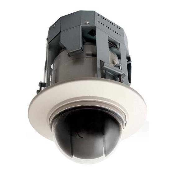
Page 115: Drawings
Drawings IPD-Q38 Flush/Tile mount Type... - Page 116 Pendant type...
- Page 117 Ikegami Electronics (U.S.A.), Inc. 37 Brook Avenue, Maywood, New Jersey 07607, U.S.A. Phone: (201) 368-9171, FAX 201-569-1626 Ikegami Electronics (U.S.A.), Inc, West Coast Office 2631 Manhattan Beach Blvd., Redondo Beach, C.A. 90278 Phone: (310) 297-1900, FAX (310) 536-9550 Ikegami Electronics (Europe) GmbH Ikegami Strasse 1, D-41460 Neuss, Germany TEL.
Need help?
Do you have a question about the IPD-Q38 and is the answer not in the manual?
Questions and answers