
Related Manuals for HAMPTON BAY Florentine


Summary of Contents for HAMPTON BAY Florentine
-
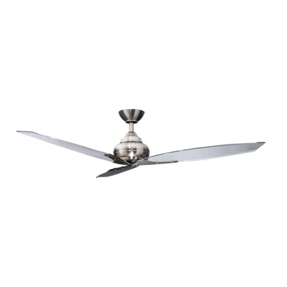
Page 1: Ceiling Fan
527-541 Florentine IV Ceiling Fan Owner’s Manual Florentine IV Ventilador de Techo de 1,42 Manual del Propietario... - Page 2 Florentine IV by Hampton Bay ®...
-
Page 3: Table Of Contents
Thank you for purchasing our ceiling fan. This product has been manufactured with the highest standards of safety and quality. The finish of this fan is weather resistant, but over time will Ceiling Fan by Hampton Bay naturally weather and fade. Date Purchased... -
Page 4: Safety Rules
Safety Rules - Read and Save These Instructions To reduce the risk of electric shock, insure electricity has been turned off After making electrical connections, spliced conductors should be turned at the circuit breaker or fuse box before beginning. upward and pushed carefully up into outlet box. The wires should be spread apart with the grounded conductor and the equipment-grounding All wiring must be in accordance with the National Electrical Code conductor on one side of the outlet box and ungrounded conductor on the... -
Page 5: Unpacking Your Fan
Unpacking Your Fan Unpack your fan and check the contents. You should have the following items: Set of blades (3) Fan motor assembly Blade Attachment Hardware (13 screws, 13 nut, 13 rubber washers, Canopy assembly Blade arms (3) 13 metal washers, Allen wrench) Ball/downrod assembly (1) 4-speed wall control with 2 mounting &... -
Page 6: Installing Your Fan
Installing Your Fan Provide Strong Support Tools Required Figures 1~3 are examples of different ways to mount the outlet box. Phillips screwdriver, straight slot screwdriver, step ladder and wire cutters. Recessed Ceiling Outlet Box Mounting Plate Mounting Options Figure 3 Outlet Box Note: You may need a longer downrod to If there isn't an existing UL listed mounting box,... - Page 7 Hanging the Fan WARNING Motor Wires FAILURE TO PROPERLY INSTALL COTTER PIN AS NOTED IN STEP 5 COULD RESULT IN FAN REMEMBER to turn off the power. Follow the Pin in Locked LOOSENING AND POSSIBLY FALLING. Ceiling Canopy Positioon steps below to hang your fan properly. Remove the decorative canopy bottom cover Ball/Downrod Tighten two set screws at top of the fan motor...
-
Page 8: Changing The Downrod
Changing the Downrod Installing Fan to UL Listed Outlet Box the Electrical Box (Optional) NOTE: Your fan comes with a 4" downrod WARNING 120V attached to the hanger ball. In addition you have Wires TO REDUCE THE RISK OF FIRE, ELECTRIC been provided with a 6"... -
Page 9: Making The Electrical Connections
Making the Electrical SUPPLY CIRCUIT ground wire to it; otherwise connect the wall transmitter's ground wire directly to one of the Connections screws from the outlet box. Ground WARNING Conductor BLACK TO AVOID POSSIBLE ELECTRICAL SHOCK, FAN 4 SPEED Outlet Box CONTROL Switch Outlet Box... - Page 10 Finishing the Fan Installing the Wall WARNING Installation MAKE SURE THE TAB ON THE HANGING Transmtter BRACKET PROPERLY SITS IN THE GROOVE IN THE HANGER BALL BEFORE ATTACHING Remember to shut the power off at the circuit Tuck connections neatly into ceiling outlet THE CANOPY TO THE BRACKET BY TURNING breaker or fuse box.
-
Page 11: Attaching The Fan Blades
Attaching the Fan Blades Metal washers Allen Wrench This fan comes with 3 blades, following the below Rubber washers Screws procedure for accurate installation: Step 1. Attach the blades to the blade brackets using the screws, nuts, metal washers and rubber Hole Third Blade washers provided as shown in Figure 13, be sure... -
Page 12: Operating Your Fan
Operating Your Blade Balancing The following procedure should correct most fan Touching Ceiling wobble. Check after each step. Check that all blade and blade bracket screws Restore power to ceiling fan and test for proper are secure. operation. Most fan wobble problems are caused when The fan 4-speed control is used to set the fan speed blade levels are unequal. -
Page 13: Care Of Your Fan
Care of Your Fan Troubleshooting PROBLEM SOLUTION Here are some suggestions to help you maintain your fan. Fan will not start Check main and branch circuit fuses or breakers. Because of the fan's natural movement, some connections may become loose. Check the Check line wire connections to the fan. -
Page 14: Specifications
Specifications FAN SIZE SPEED VOLTS AMPS WATTS N.W. G.W. C.F. 0.17 1396 Medium 0.24 1908 8.63 kgs 10.0 kgs 56” 1.36’ (19.04 lbs) (22.06 lbs) Medium High 0.39 3608 High 0.48 5136 These are approximate measures. They do not include Amps and Wattage used by the light kit. -
Page 15: Warranty Information
(lifetime warranty on motor) IMPORTANT NOTE: The Hampton Bay warrants the fan motor to be free from defects in workmanship and material present at time To ensure warranty service if ever of shipment from the factory for a period of lifetime after the date of purchase by the original purchaser.
Need help?
Do you have a question about the Florentine and is the answer not in the manual?
Questions and answers