
Related Manuals for ESAB RS 400


Summary of Contents for ESAB RS 400
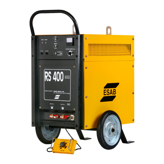
- Page 1 RS 400 / RS 400 with ESU Thyristorised MMA Welding Power Source Instruction manual...
- Page 2 RS 400 / RS 400 with ESU THYRISTORISED MMA WELDING POWER SOURCE Instruction manual Installation, Operation & General maintenance...
-
Page 3: Table Of Contents
MAINTENANCE & INSPECTION AFTER SALES SERVICE FAULT FINDING WIRING DIAGRAM RS 400 (STANDARD) WIRING DIAGRAM RS 400 WITH ESU TEST POINT VOLTAGES IN CONTROL PCB SPARES IDENTIFICATION – RS 400 13 - 16 RECOMMENDED LIST OF SPARES – RS 400... -
Page 4: Safety
SAFETY Users of ESAB welding equipment have the ultimate responsibility for ensuring that anyone who works on or near the equipment observes all the relevant safety precautions. Safety precautions must meet the requirements that apply to this type of welding equipment. The following recommendations should be observed in addition to the standard regulations that apply to the workplace. - Page 5 Read and understand the instruction manual before installing or operating. ESAB can provide you with all necessary welding protection and accessories. WARNING Arc welding and cutting can be injurious to yourself and others. Take precautions when welding. Ask for your employer’s safety practices which should be based on manufacturers’...
-
Page 6: Assembling
ACCESSORIES LIST FOR THYRISTORISED WELDING RECTIFIER RS 400 Fuse, element 1A 1 piece Instruction Manual 1 piece RATING OF RS 400 THYRISTORISED MMA WELDING POWER SOURCE CHARACTERISTICS CONSTANT CURRENT TYPE Input: SUPPLY VOLTAGE, PHASE & FREQUENCY 415± 10%, 3 Phases, 50 Hz, AC... -
Page 7: Items For Installation
Remote Control Unit RS 400 Welding cable (Optional) Work Piece Welding cable Switch Box (Input) Input Cable Connector for Remote Control Unit Electrode Holder Negative Terminal Electrode Positive Terminal Terminal Block input Control Cable for RCU RS 400 ON OFF Switch... -
Page 8: Welding Operations
WELDING OPERATION Once the installation of the equipment is completed, connect the work Cable to the negative output terminal and the cable end of the electrode holder to the Positive output terminal. These cable connections should be tightened properly to avoid electrical heating due to loose connections. Put the main Switch box in ‘ON’. -
Page 9: Working Principles Of Esu Unit
Energy Saving Circuit is an optional feature in the RS 400 Machine. Working principle of the ESU is explained below: The extra items fitted in RS 400 having the Energy Saving feature comprises of: a) Control Transformer for ESU b) Control PCB for ESU c) Line Contactor- ESU The unit, when energized provides an auxiliary low 55-60 VD.C to the output of the... -
Page 10: After Sales Service
In case of any abnormality observed during usage of the equipment, which could not be rectified at site, please contact immediately Area Sales Manager of the nearest unit of ESAB INDIA LIMITED with the following details: 1) Serial Number of the equipment & type 2) Nature of the complaint with the relevant details, if possible and the details of Input Supply. -
Page 11: Fault Finding
FAULT FINDING Abnormality Possible Cause Corrective action Welding automatically The equipment is over loaded Wait and keep the power switch stops and the WARN ‘ON’ to keep the fan running at LAMP glows no load. The Warning Lamp should get off within 10-15 minutes. - Page 12 ADDITIONAL FAULT FINDING FOR MACHINES WITH ESU Abnormality Possible Cause Corrective action Arc striking can not be Faulty Line Contactor Check and replace done Faulty ESU PCB Check and replace Faulty ESU Control Check and replace Transformer Line Contactor does not Faulty ESU PCB Check and replace get off after a certain...
-
Page 13: Wiring Diagram Rs 400 (Standard)
WIRING DIAGRAM- RS 400 (Standard) -
Page 14: Wiring Diagram Rs 400 With Esu
WIRING DIAGRAM- RS 400 (with ESU) -
Page 15: Test Point Voltages In Control Pcb
TEST POINT VOLTAGES IN RS 400 CONTROL PCB All voltages except Gate- Cathode measurements are to be measured with respect to TP1 (0V point on Control PCB) TEST POINT VALUE +15 V ± 0.2 V DC -15 V ± 0.2 VDC +12 V ±... -
Page 16: Spares Identification - Rs 400
SPARES IDENTIFICATION OF RS 400 RS 400 SIDE VIEW... - Page 17 RS 400 TOP VIEW...
- Page 18 RS 400 FRONT VIEW...
- Page 19 RS 400 REAR VIEW...
-
Page 20: Recommended List Of Spares - Rs 400
RECOMMENDED LIST FOR SPARE SPARTS SL. NO. ITEM CODE DESCRIPTION Recommended Holding 1-10 Above 10 1611621199 On-Off Rotary Switch 1611621300 Synchronizing PCB 1611642019 Fuse Element 1 A 1611642020 Amp/ Volt Selector Switch 1611642021 Dual Scale Ammeter + Voltmeter 1611642023 Filter Capacitor 8 µF Bleeder Resistor 10 Ω... - Page 21 Web: www.esabindia.com...
Need help?
Do you have a question about the RS 400 and is the answer not in the manual?
Questions and answers