
Related Manuals for Life Fitness G3


Summary of Contents for Life Fitness G3
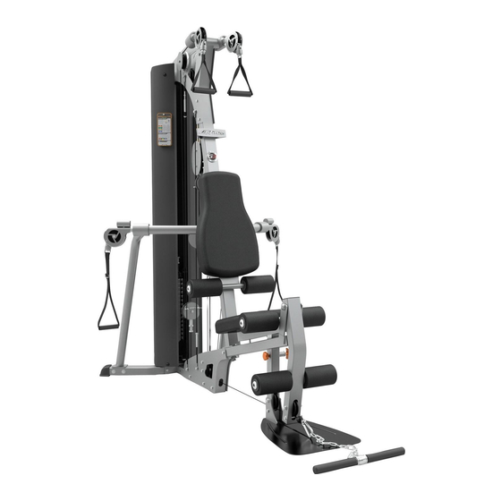
- Page 1 G3 GYM SYSTEM ASSEMBLY INSTRUCTIONS G3-001 / CLASS H / 09/19/08 / 8600401 / REV B-2...
-
Page 2: Table Of Contents
AFETY NFORMATION It is the sole responsibility of the purchaser of LIFE FITNESS products to read the owner's manual, warning labels and instruct all individuals, whether they are the end user or supervising personnel on proper usage of the equipment. - Page 3 7. Before any use, examine all accessories approved for use with the LIFE FITNESS equipment for damage or wear, including, but not limited to, examining the Hammer Strength Training Vest for damage or wear on the rings or the webbing or stitching holding the rings in place.
-
Page 4: General Notes
MPORTANT OTES Thank you for purchasing the Life Fitness G3 Gym System. Please read these instructions thor- oughly and keep them for future reference. This product must be assembled on a flat, level surface to assure its proper function. DO NOT securely tighten any frame connections until the entire frame has been assembled, unless otherwise stated. -
Page 5: Gym Layout
2’ 3’ 9’ 1’ 2’ 3’ 4’ 5’ 6’ 7’ 8’ 9’ G3 F OOTPRINT = 1' QUARE AXIMUM EIGHT 300 lbs (136 kg) INIMUM EQUIRED SABLE PACE Length = 90 inches (229 cm) 7' 6" Width = 103 inches (262 cm) 8' 7"... -
Page 6: Parts List
ARTS NOTE: Some of the components may be pre-assembled. Key Description Key Description FRONT BASE SNAP LINK UPRIGHT GUIDE BRACKET BASE CONNECTOR 5-PRONG KNOB REAR BASE ROLLER PAD CAP RIGHT ARM PLASTIC WASHER LEFT ARM 1/2" RH WASHER SEAT ADJUST RH CAP LEG PEDESTAL 3/8 X 3/4"... -
Page 7: Cabling Diagrams
ABLING IAGRAM ITEM QTY. PART NO. DESCRIPTION 7726201 COUPLER, QUICK CONNECT 7726401 HSNG, QUICK CONNECT 7726301 SLEEVE, QUICK CONNECT 3249901 SPRING, QUICK CONNECT 3250002 M5 X 0.8 HXS SOC CS ST BZ X 8 ABLE SSEMBLY Slide parts onto cable in the following order: Item 2, Item 4, Item 3. Insert cable end into Item 1. - Page 8 ABLING IAGRAM...
- Page 9 ABLING IAGRAM...
- Page 10 ABLING IAGRAM...
- Page 11 ABLING IAGRAM...
-
Page 12: Assembly Instructions
IGURE 3/8 X 2-3/4” 57 3/8 X 3-3/4” 3/8 X 3” • Loosely assemble two BASE PLATES (11) to the FRONT BASE (1) and the BASE CONNECTOR (3) using four 3/8 x 3-3/4" BOLTS (57) and four 3/8" SILVER LOCK NUTS (63). See Figure 1. •... - Page 13 3/8 X 4-1/4” 3/8 X 3-3/4” IGURE • Loosely assemble the RIGHT ARM (5) and REAR BASE (4) using two 3/8 x 3-3/4" BOLTS (57), two 3/8" WASHERS (64) and two 3/8" SILVER LOCK NUTS (63). • Loosely assemble the LEFT ARM (6) and REAR BASE (4) using two 3/8 x 3-3/4" BOLTS (57), two 3/8"...
-
Page 14: Weight Plate
IGURE Make sure that the WEIGHT PLATES (21) are assembled as shown in Figure 3 and the HEAD PLATE ASSEMBLY (23) is assembled as shown in Figure 4. IGURE... - Page 15 Bottom Shroud Bracket IGURE • Place the GUIDE RODS (18) through the BOTTOM SHROUD BRACKET and into the REAR BASE (4) as shown in Figure 5. • Lubricate the GUIDE RODS (18) with the included silicon package. • Slide two WEIGHT STACK SPACERS (33) and two WEIGHT STACK CUSHIONS (28) over the GUIDE RODS (18).
- Page 16 3/8 X 3-3/4” IGURE A. Swing the GUIDE RODS (18) into the guide rod bushings in the RIGHT BOOM PLATE (14) and LEFT BOOM PLATE (15) as shown in Figure 6. B. Loosely assemble the RIGHT BOOM PLATE (14) and LEFT BOOM PLATE (15) to the UPRIGHT (2) using three 3/8 x 3-3/4"...
- Page 17 1/2 X 104mm SPRING PIN IGURE • Securely assemble the FIVE PRONG KNOB (43) to the FRONT BASE (1) as shown. • Insert the SEAT ADJUST (7) into the FRONT BASE (1) as shown. The seat height can be adjust- ed using the Spring Pin and can be secured with the FIVE PRONG KNOB (43).
- Page 18 IGURE • Detach the Short Cable from both REAR GUIDE CABLES (74) as shown in Figure 9 (B). • Slide the Long Cables of the REAR GUIDE CABLES (74) through the eyelets of the GUIDE BRACKET (42) as shown in Figure 9 (B). Reattach the Short Cable of the REAR GUIDE CABLES (74) to the Long Cable, leaving the GUIDE BRACKET (42) loose.
- Page 19 MPORTANT NCOIL AND STRAIGHTEN ALL CABLES TO REMOVE ALL TWISTS BEFORE INSTALLING • Assemble the WEIGHT STACK PIN (27) to the HEAD PLATE ASSEMBLY (23) as shown in Figure 10. • Screw the long threaded end of the WEIGHT STACK CABLE (29) into the end of the HEAD PLATE ASSEMBLY (23).
- Page 20 3/8 X 4-1/4" TURN BUCKLE SHORT CABLE IGURE • Loop the WEIGHT STACK CABLE (29) around one 3-1/2" PULLEY (37). • Assemble the 3-1/2" PULLEY (37) with the WEIGHT STACK CABLE (29) around it to the RIGHT and LEFT BOOM PLATES (14 & 15) using one 3/8 x 4-1/4" SILVER BOLT (68), two 3/8" FLAT WASHERS (64), two GUIDE CABLES (65), two 3/8 x 1"...
- Page 21 IGURE • Loop the BOOM CABLE (32) around one 3-1/2" PULLEY (37). • Assemble the 3-1/2" PULLEY (37) with the BOOM CABLE (32) looped around it to the GUIDE BRACKET (42), using one 3/8 x 1-3/4" BOLT (53) and one 3/8" SILVER LOCK NUT (63). •...
-
Page 22: X 3-3/4" Bolt
3/8 X 4-1/4” 68 3/8 X 3” TURN BUCKLE SHORT CABLE 3/8 X 3-3/4” 57 IGURE • Securely assemble the ball end of the LEG CABLE (30) and one 3-1/2" PULLEY (37) to the LEG PEDESTAL (8), using one 3/8 x 3-3/4" BOLT (57), two 3/8 x 1-1/16" FLANGE SPACERS (49), and one 3/8"... -
Page 23: Pulley
• Securely assemble one 3-1/2" PULLEY (37) to the PULLEY PLATES (10), using one 3/8 x 1-3/4" BOLT (53) and one 3/8" SILVER LOCK NUT (63). NOTE: Loop the LEG CABLE (30) over the PULLEY (37) before assem- bling the PULLEY PLATES (10) as shown in Figure 14. - Page 24 IGURE • Route the ARM CABLE (31) through the LEFT ARM (6) as shown in Figure 16. • Loop the ARM CABLE (31) around one 4-1/2" PULLEY (38). • Securely assemble the 4-1/2" PULLEY (38) with the ARM CABLE (31) around it to the LEFT ARM (6), using one 3/8 x 2"...
- Page 25 IGURE • Securely assemble two 3-1/2" PULLEYS (37) to the BASE PLATES (11), using two 3/8 x 3-3/4" BOLTS (57), one 3/8 x 1" SPACER (51) and two 3/8" SILVER LOCK NUTS (63). • Loop the ARM CABLE (31) between the two PULLEYS (37) around one 3-1/2" PULLEY (37) as shown in Figure 17.
- Page 26 IGURE • Route the ARM CABLE (31) through the RIGHT ARM (5) as shown in Figure 18. • Loop the ARM CABLE (31) around one 4-1/2" PULLEY (38). • Securely assemble the 4-1/2" PULLEY (38) with the ARM CABLE (31) around it to the RIGHT ARM (5), using one 3/8 x 2"...
- Page 27 IGURE • Insert the ARM CABLE (31) ends through the SWIVEL PULLEY ASSEMBLIES (72). • Insert the SWIVEL PULLEY ASSEMBLIES (72) into the LEFT ARM (6) and the RIGHT ARM (5). • Secure the SWIVEL PULLEY ASSEMBLIES (72) in the LEFT ARM (6) and the RIGHT ARM (5) using one C-RING (12) each.
- Page 28 IGURE 3/8 X 1-1/4” 1/2 X 5-3/4” • Securely assemble one BACK PAD (9) to the BACK PAD ADJUSTMENT (71) using two 3/8 x 1- 1/4" BOLTS (70) and two 3/8" WASHERS (64). • Securely assemble the BACK PAD ADJUSTMENT (71) to the UPRIGHT (2), using one 1/2 x 5- 3/4"...
- Page 29 IGURE ADJUSTMENT CABLE USING JAM NUT ADJUSTMENT TURN BUCKLE CABLE USING ADJUSTMENT JAM NUT • Make adjustments to the cables’ tension at the locations shown in Figure 22. • Adjust the Turnbuckle on each GUARD CABLE (65) to change the tension of the GUIDE CABLES (65).
- Page 30 PARTS LIST DESCRIPTION DESCRIPTION LEFT SHROUD 3/8 X 1” BUTTON HEAD BOLT 3/8” BLACK SAE W ASHER RIGHT SHROUD 3/8 X 2-1/2” BOLT TOP SHROUD BRACKET 3/8” LOCK NUT BOTTOM SHROUD BRACKET 7 3/8 X 2-1/2” FIGURE 23 RIGHT BOOM PLA TE LEFT BOOM PLA TE •...
- Page 31 B. One M4 X 20mm SHOULDER BOLT, M4 WASHER, and M4 NUT are pre-assembled to the shroud. Use use the M4 X 20MM SHOULDER BOLT to hang the G3 Exercise Cards. This completes the assembly of the G3 Gym System.
-
Page 32: Maintenance
AINTENANCE We recommend cleaning your product (pads and frame) on a regular basis, using warm soapy water. Touch-up paint can be purchased from your Life Fitness customer service repre- sentative at 1-800-351-3737. Inspect equipment daily. Tighten all loose connections and replace worn parts immediately. -
Page 33: Warranty
1. LIMITED WARRANTY ON FRAME AND WELDS. If the frame of the Life Fitness product or a weld should crack or break, it will be repaired or replaced by Life Fitness. Terms: Lifetime – for so long as the Customer owns the Life Fitness product. -
Page 34: Contact Information
5100 N River Road C/Frederic Mompou 5,1º1ª China and Hong Kong 08960 Sant Just Desvern Barcelona Schiller Park, IL 60176 U.S.A Life Fitness Asia Pacific LTD SPAIN Telephone: +1(847) 288 3300 Room 2610, Miramar Tower Telephone: (+34) 936 724 660...
Need help?
Do you have a question about the G3 and is the answer not in the manual?
Questions and answers