Advertisement
Quick Links
Advertisement

Related Manuals for Tally T9020


Summary of Contents for Tally T9020
- Page 1 ® T9020 Maintenance Manual Laser Printer...
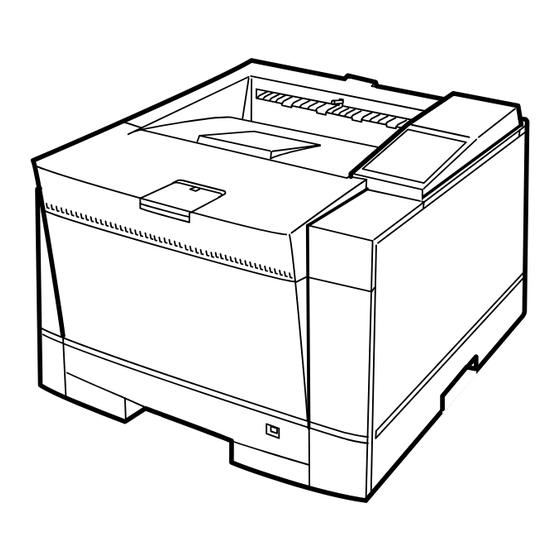
- Page 2 2. PARTS LIST AND PARTS DRAWING OF PRINTER MECHANISM 2.1 Visual Index of Parts 2.15 Print Unit 2.2 Upper Cover 2.3 Printer 2.12 Front Door ASY 2.10 Paper Eject Unit 2.11 Heat Roller (HR) Unit 2.4 Printer M Unit 1 2.13 Paper Tray (250) 2.14 Paper Tray (500) 2.9 Laser Diode (LD)
-
Page 3: Upper Cover
2.2 Upper Cover 2 - 2... - Page 4 2.2 Upper Cover APPLICATION LEVEL/QUANTITY PART NUMBER DESCRIPTION B15X B25X (230V) (120V) M3854 20WA (120V) M3854 20WB (230V) 1 ~ 13 UPPER COVER ASY 1 ~ 7 UPPER DOOR ASY UPPER DOOR ASY STOPPER1 STOPPER2 LABEL1 LABEL2 LABEL A A3 LABEL UPPER COVER UD GUIDE L UD GUIDE LL...
- Page 5 2.3 Printer 2 - 4...
- Page 6 2.3 Printer APPLICATION LEVEL/QUANTITY PART NUMBER DESCRIPTION B15X B25X (120V) (230V) 1 ~ 7 PAPER EJECT UNIT DUPLEX UNIT (OPTION) 2 - 5...
- Page 7 2.4 Printer M Unit -1 2 - 6...
- Page 8 2.4 Printer M Unit -1 APPLICATION LEVEL/QUANTITY PART NUMBER DESCRIPTION B15X B25X (120V) (230V) 1 ~ 4 SENSOR LEVER 398 305 PHOTO SENSER ASY DA97AA CONNECTOR ASY GUIDE PLATE ASY 398 306 ROM BOARD 398 307 ROM BOARD 398 308 DCV01AA PT BRACKET BRACKET T...
- Page 9 2.5 Printer M Unit -2 2 - 8...
- Page 10 2.5 Printer M Unit -2 APPLICATION LEVEL/QUANTITY PART NUMBER DESCRIPTION B15X B25X (120V) (230V) 1 ~ 10 STUDL 7 ~ 9 398 310 FAN ASY FAN BRACKET 11~17 PR GUIDE L ASY PR GUIDE L COVER OPEN SWITCH 398 311 STEEL BALL SPRING STOPPER...
- Page 11 2.6 Printer M Unit -3 2 - 10...
- Page 12 2.6 Printer M Unit -3 APPLICATION LEVEL/QUANTITY PART NUMBER DESCRIPTION B15X B25X (120V) (230V) STUD R SHEET 8~12 PR GUIDE R ASY PR GUIDE R STEEL BALL SPRING STOPPER 14~25 PT GUIDE R ASY PT GUIDE R 15~19 398 319 PPS BOARD ASY WPS BOARD ASY SWITCH ARM...
- Page 13 2.7 Printer M Unit -4 (1/2) 2 - 12...
- Page 14 2.7 Printer M Unit -4 (1/2) APPLICATION LEVEL/QUANTITY PART NUMBER DESCRIPTION B15X B25X (120V) (230V) 1 ~ 16 SHAFT P ASY 398 316 ROLLER P ASY GEAR SPRING BEARING GEAR P1 ROLLER L ASY ROLLER L PLATE R PLATE L SCREW E RING ROLLER R ASY...
- Page 15 2.7 Printer M Unit -4 (2/2) 2 - 14...
- Page 16 2.7 Printer M Unit -4 (1/2) APPLICATION LEVEL/QUANTITY PART NUMBER DESCRIPTION B15X B25X (120V) (230V) STOPPER SPONGE 3 LABEL 398 321 HV BOARD 398 322 POWER BOARD 398 323 POWER BOARD 398 324 WD98AA PLATE 2 - 15...
- Page 17 2.8 Base Frame ASY (1/2) 2 - 16...
- Page 18 2.8 Base Frame ASY (1/2) APPLICATION LEVEL/QUANTITY PART NUMBER DESCRIPTION B15X B25X (120V) (230V) 1 ~ 79 398 325 FEED ROLLER BEARING PF BEARING GEAR F BEARING GEAR FA GEAR FB 398 326 STEPPING MOTOR BEARING R SPRING R GEAR FC GEAR RA DCH PLATE SPRING HV5...
- Page 19 2.8 Base Frame ASY (2/2) 2 - 18...
- Page 20 2.8 Base Frame ASY (2/2) APPLICATION LEVEL/QUANTITY PART NUMBER DESCRIPTION B15X B25X (120V) (230V) GEAR BEARING PF LEVER ASY 54~56 GUIDE F ASY PINCH ROLLER SPONGE SHEET LABEL LABEL GUIDE SHEET B PLATE GUIDE PLATE PLATE PLATE ASY 71~79 398 331 TRCG UNIT SCREW SHEET F1...
- Page 21 2.9 LD Stay ASY 2 - 20...
- Page 22 2.9 LD Stay ASY APPLICATION LEVEL/QUANTITY PART NUMBER DESCRIPTION B15X B25X (120V) (230V) 1~10 LD STAY SPRING 398 332 DCH LED ASY BRACKET ASY PLATE 398 333 LD UNIT 398 334 LD UNIT LD CABLE ASY FERRITE CORE 17~30 STACKER1 ASY 18~19 23~25 398 335...
- Page 23 2.10 Paper Eject Unit 2 - 22...
- Page 24 2.10 Paper Eject Unit APPLICATION LEVEL/QUANTITY PART NUMBER DESCRIPTION B15X B25X (120V) (230V) 1~33 PAPER EJECT UNIT FRAME ASY 398 336 ROLLER ASY GUIDE A GUIDE B GUIDE C GUIDE D GUIDE E GUIDE F GUIDE G 12~16 SIDE FRAME ER ASY GEAR3 GEAR D4 30~32...
- Page 25 2.11 HR Unit (1/2) 2 - 24...
- Page 26 2.11 HR Unit (1/2) APPLICATION LEVEL/QUANTITY PART NUMBER DESCRIPTION B15X B25X (120V) (230V) 1~48 398 337 HR UNIT (120V) 398 338 HR UNIT (230V) 1~48 1~19 HR BASE UNIT BACK UP ROLLER ASY HEAT ROLLER GEAR HR RING HR SPRING BR 7~13 UPPER FRAME ASY 14~16...
- Page 27 2.11 HR Unit (2/2) 2 - 26...
- Page 28 2.11 HR Unit (2/2) APPLICATION LEVEL/QUANTITY PART NUMBER DESCRIPTION B15X B25X (120V) (230V) 42~43 ROLLER HOLDER R ASY CABLE ASY CONNECTOR TUBE 2 - 27...
- Page 29 2.12 Front Door ASY 2 - 28...
- Page 30 2.12 Front Door ASY APPLICATION LEVEL/QUANTITY PART NUMBER DESCRIPTION B25X B15X (120V) (230V) 1~19 FRONT DOOR ASY 2 - 29...
-
Page 31: Paper Tray
2.13 Paper Tray (250) 2 - 30... - Page 32 2.13 Paper Tray (250) APPLICATION PART NUMBER LEVEL/QUANTITY DESCRIPTION F704 1~32 PAPER TRAY (250) 398 339 S HOLDER ASY HOLDER SPRING PAPER GUIDE L PAPER GUIDE R RACK PINION P COVER ASY 10~13 P PLATE ASY SPRING PLATE HOLDER L PLATE HOLDER R PH SPRING DIAL ASY...
- Page 33 2.14 Paper Tray (500) 2 - 32...
- Page 34 2.14 Paper Tray (500) APPLICATION PART NUMBER LEVEL/QUANTITY DESCRIPTION F755 1~53 PAPER TRAY (500) 398 340 S HOLDER ASY HOLDER SPRING 8~13 GUIDE L ASY 10~11 TRAY GUIDE R ASY GUIDE HOLDER R RACK PINION COVER P CHIP 21~27 P PLATE ASY P.
-
Page 35: Print Unit
2.15 Print Unit 2 - 34... - Page 36 2.15 Print Unit APPLICATION LEVEL/QUANTITY PART NUMBER DESCRIPTION B15X B25X (120V) (230V) PRINT UNIT DEV UNIT DRUM UNIT P LOCK ASY “ TONER BOTTLE 2 - 35...
-
Page 37: Duplex Unit
2.16 Duplex Unit (1/2) 2 - 36... - Page 38 2.16 Duplex Unit (1/2) APPLICATION LEVEL/QUANTITY PART NUMBER DESCRIPTION B25X B15X (120V) (230V) 1~56 DUPLEX UNIT 1~40 DUPLEX SUB ASY 1~13 UPPER ASY 14~39 LOWER ASY 16~18 398 341 FEED ROLLER 398 342 TIMING BELT E RING 41~55 TRAY SUB ASY 2 - 37...
- Page 39 2.16 Duplex Unit (2/2) 2 - 38...
- Page 40 2.16 Duplex Unit (2/2) APPLICATION LEVEL/QUANTITY PART NUMBER DESCRIPTION B25X B15X (230V) (120V) SCREW 2 - 39...
-
Page 41: Feeder Unit
2.17 Feeder Unit-1 (1/2) 2 - 40... - Page 42 2.17 Feeder Unit-1 (1/2) APPLICATION LEVEL/QUANTITY PART NUMBER DESCRIPTION F957 F777 (250) (500) 1~28 FEEDER SUBASY FEEDER SUBASY“ M FRAME FU ASY“ M FRAME FU ASY“ 8~10 PT GUIDE L ASY PT GUIDE L ASY PT GUIDE SPRING PLATE 11~22 PT GUIDE R2 ASY 13~17 398 343...
- Page 43 2.17 Feeder Unit-1 (2/2) 2 - 42...
- Page 44 2.17 Feeder Unit-1 (2/2) APPLICATION LEVEL/QUANTITY PART NUMBER DESCRIPTION F957 F777 (250) (500) PT GUIDE R ASY CABLE FU ASY 2 - 43...
- Page 45 2.18 Feeder Unit-2 (1/2) 2 - 44...
- Page 46 2.18 Feeder Unit-2 (1/2) APPLICATION LEVEL/QUANTITY DESCRIPTION PART NUMBER F777 F957 (250) (500) FEEDER UNIT (250) FEEDER UNIT (500) 1~38 M FRAME FU ASY M FRAME FU ASY SHEET 3~10 L FRAME FU ASY L FRAME FU ASY 398 345 WT97AA 398 346 WT97AC...
- Page 47 2.18 Feeder Unit-2 (2/2) 2 - 46...
- Page 48 2.18 Feeder Unit-2 (2/2) APPLICATION LEVEL/QUANTITY PART NUMBER DESCRIPTION F957 F777 (250) (500) 40~46 41~42 PR SHAFT FU ASY PR SHAFT FU ASY 398 351 ROLLER P ASY 398 352 PICK ROLLER ASY 398 353 HOLDER ASY GEAR F3 BEARING PF2 S.
- Page 49 GID 5220 • Video data transfer – When the mechanism controller starts the motor, paper moves along the paper path. The mechanism controller checks the sensor on the paper path. When paper reaches the position where video data needs to be created, the main controller starts video data transfer from the LSI-1.
- Page 50 GID 5220 2.3.8 Operator panel The operator panel has eight switches, four LEDs, and one LCD with 16 columns by two lines. The switches are used for operation, and the LEDs and LCD are used to display error or status information. Figure 5220-10 shows the operator panel.
- Page 51 GID 5220 2.3.9 Power supply This section explains the power supply of the printer. The power supply outputs +5 V to logic circuits and +24 V to the printer mechanism driver. AC voltage is supplied to the heater in the fusing unit. Figure 5220-11 is a power supply block diagram •...
- Page 52 Leer...
- Page 53 “All rights reserved. Translations, reprinting or copying by any means of this manual complete or in part or in any different form requires our explicit approval. We reserve the right to make changes to this manual without notice. All care has been taken to ensure accuracy of information contained in this manual. However, we cannot accept responsibility for any errors or damages resulting from errors or inaccuracies of information herein.”...
- Page 54 +34 91 7219 936 P.O.Box 97018 http://www.Tally.it 8301 South, 180th Street Kent, WA 98032 SINGAPORE U.S.A. Tally AMT Printer Pte. Ltd Phone: +1 425 25155 00 63, Hillview Avenue Fax: +1 425 25155 20 #08-22, Lam Soon Industrial Building http://www.Tally.com...
Need help?
Do you have a question about the T9020 and is the answer not in the manual?
Questions and answers