
Related Manuals for JR JR DSM 12x


Summary of Contents for JR JR DSM 12x
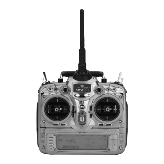
- Page 1 12-CHANNEL COMPUTER RADIO SYSTEM WITH SPEKTRUM 2.4GHz DSM TECHNOLOGY APPLICATIONS AND PROGRAMMING GUIDE...
-
Page 2: Servo Connections
Introduction Programming a model for the first time, especially with a new programming a governor and programming a countdown timer radio, can be confusing. Following are programming guides to start on throttle up. While there are an endless number of that give step-by-step instructions for programming a giant- programming methods and options, the following setup guide scale aerobatic airplane, an aircraft with dual flap setup, a... - Page 3 Step 1. Selecting a Model Memory 1. Press and hold the ENT button while turning on the power 2. Using the roller, highlight 84. Model SEL and press the switch to enter the System Mode List screen. roller to access the Model Select screen. 3.
- Page 4 Step 2. Selecting the Model Type (Acro) 1. In System Mode List screen use the roller to highlight 89. Type SEL. and press the roller to access the Type Select screen. 2. Rotate the roller to highlight ACRO then press the roller to Note: All programming in the selected model memory will enter the ACRO program.
- Page 5 Step 4. Naming the Model 1. In System Mode List screen use the roller highlight 81. MDL Name and press the roller to access the Model Name screen. 2. Rotate the roller to select the desired position to place a letter or number (up to 16 characters) and press the roller to access the Character screen.
-
Page 6: Trim System
Trim System The Trim System Code 83 allows the adjustment of the trim and aux trim off. The remaining settings are recommended authority and also allows the flap trim and aux trim levers to to be left at the default settings, 100% throttle, 4 for Aileron, be turned on or off. - Page 7 Flight Mode Naming The flight mode name function code 92 can be used to rename Mode 1 can be renamed SNAP, and Flight Mode 2 can be the flight modes throughout the system. This allows customized renamed NORMAL (NORM). A short name can then be selected programming for at-a-glance awareness of the current flight from the complete flight mode name.
- Page 8 3. Rotate the roller and highlight the * and – marks as desired under each Flight Mode name to select the abbreviated short name. A * mark indicates the character will be used in the short name, a – mark indicates the character will not be used in the short name.
-
Page 9: Device Select
Device Select Device Select code 17 allows the activation of flight modes, 3) can be activated as well in the Device Select function, using selecting a throttle hold switch, flap trim selection, flight mode 2 switches combined to select the desired flight mode in flight. trim selection, and switch selection and activation for all aux Generally most fliers use 3 flight modes. - Page 10 3. Rotate the roller to highlight INH next to Flight Mode then press the roller. The available switch positions screen will appear. 4. Rotate the roller to select the Elevator D/R switch then press the roller to select it. If another switch is desired, choose it in the same manor.
-
Page 11: Wing Type
Wing Type The Wing Type menu is used to select the wing type of the Twin Engine. In this example, we will select 4 servo aileron and model : Normal for single aileron servo, Flaperon for dual mate the flap channel Aux1 to elevator for a dual elevator setup, aileron servo, Delta type for delta wing or elevon models, and and mate channel 9 Aux4 to rudder for dual rudder servo setup. - Page 12 4. Rotate the roller and highlight 4-Aile and press the roller. 5. Rotate the roller and highlight INH under ELEV and press the roller. 6. Rotate the roller and highlight FLAP and press the roller. 7. Rotate the roller and highlight INH under RUDD and press the roller.
- Page 13 Step 9. Binding 1. With the system installed in the aircraft, insert the bind plug 4. Press and hold the bind button on the back of the in the bind receptacle. transmitter while turning on the power switch. Within a few seconds the system should connect.
-
Page 14: Dual Rate And Exponential
Step 11. Travel Adjust 1. In the Function List screen use the roller to highlight 12. TRVL adjust and press the roller to access the Travel adjust screen. 2. Rotate the roller to highlight the desired channel that Note: For most aircraft, the best mechanical advantage you wish to adjust the travel adjust and press the roller is to set the travel adjust to 125% or higher and adjust to access that channel. - Page 15 Step 12. Adjusting Rate and Expo Values 1. In the Function List screen use the roller to highlight 13. D/R & EXP and press the roller to access the Dual Rate and Expo screen. 2. Rotate the roller to highlight the channel in the upper left of 4.
- Page 16 Step 14. Activating Throttle Hold 1. In the Function List screen use the roller to highlight 16. THRO Hold and press the roller to access the Throttle hold screen. 2. Rotate the roller and highlight INH then press the roller to access the throttle hold screen and activate throttle hold.
- Page 17 Step 15. Programming Throttle Curves 1. In the Function List screen use the roller to highlight 18. THRO CURV and press the roller to access the all servos hold screen. Press YES or NO to access the Throttle Curve screen. 2.
- Page 18 Step 16. Programming Aileron Differential When Ailerons are deflected, the Aileron that deflects downward allows adjustment of the Aileron that deflects downward without typically creates more drag than the Aileron that deflects affecting the Aileron that travels upward and, therefore, can upward.
- Page 19 Step 17. Programming the Balance Function The balance function is used to adjust the throw of dual servo 1. In the Function List screen use the roller to highlight 33. setups or quad aileron servo setups to fine-tune the throws Balance and press the roller to access the Balance screen.
- Page 20 Step 18. Programming Rudder to Aileron and Elevator Mixing The Rudd->A/E function is a pre-programmed mix, mixing 1. In the Function List screen use the roller to highlight 64. rudder to aileron and rudder to elevator and is used to improve RUDD->A/E and press the roller to access the RUDD->A/E knife - edge tracking.
- Page 21 Step 19. Programming a Throttle to Elevator Down Line Mix Most aircraft on a down line track toward the canopy, which is 1. In the Function List screen use the roller to highlight 54. not desirable for precision aerobatics. A curve type program PROG.MIX4 and press the roller to access the PROG.MIX4 mix, mixing a small amount of down elevator at low throttle, screen.
- Page 22 6. Rotate the roller to highlight ELEV and press the roller. 7. Move the throttle stick until the IN value on the lower left side of the screen displays a value of 14. STOR should appear on the lower left side of the screen above the IN value.
- Page 23 Step 20. Programming a Throttle Controlled Smoke Pump Most newer smoke pumps have adjustable flow rate set via the 1. In the Function List screen use the roller to highlight 55. transmitter. This can be set up to work with the throttle stick PROG.MIX5 and press the roller to access the PROG.MIX5 through a program mix assigned to a switch to be turned on-off.
- Page 24 6. Rotate the roller to highlight AUX5 and press the roller. 7. Move the throttle stick until the IN value at the bottom left corner of the screen is 15, STOR should appear just above the IN value, press the STOR button to store this point. 8.
- Page 25 Step 21. Programming a Timer to Start with Throttle Up 1. In System Mode List screen use the roller to highlight 91. STK PosSW and press the roller to access the Stick Switch Position screen. 2. Rotate the roller and highlight SPS0: INH and press the roller to access the available stick position channels.
-
Page 26: Timer Programming
Timer Programming 1. In the Function Mode List screen use the roller to highlight 87. Timer and then press the roller to access the Timer screen. 2. Rotate the roller and highlight Timer1:INH and press the 5. Rotate the roller to highlight Set Time then press the roller roller to access the available timer types. - Page 27 Flap System Setup Guide Following is a step-by-step programming guide to set up dual flap servos with elevator compensation, a delay to smooth the transitions between flight regimes, and auto land active to control the landing flaps with throttle. Use the following to locate the correct locations for the servos: Left Flap Servo- Channel 7/ Aux2 Right Flap Servo- Channel 6/ Aux1...
- Page 28 Step 1. Device Select Set Up 7. Press and hold the ENT button while turning on the power switch to enter the System Mode List screen. 8. Using the roller highlight 17. DeviceSEL and press the roller to access the Device Select screen. 9.
- Page 29 Step 2. Wing Type Setup 1. Press and hold the ENT button while turning on the power 2. Using the roller highlight 22. Wing Type and press the switch to enter the System Mode List screen. roller to access the Wing Type screen. 3.
- Page 30 Step 3. Flap System Programming 1. In the Function List screen use the roller to highlight 66. FLAP System and press the roller to access the FLAP System screen. 2. Determine if you want to use the Auto Land Function. If you 3.
- Page 31 4. Rotate the roller to highlight the FLAP setting in the NORM 9. Rotate the roller to set the value. This is most generally a position and press the roller. small percentage of down elevator (10-20%) to prevent the aircraft from nosing up with flap deployment. Press the 5.
- Page 32 3D Helicopter Setup Guide Following is a step-by-step programming guide for 3D a countdown timer to be activated upon throttle up. While this helicopters. The specific example below gives setup detail for a setup guide is specific to 120* CCPM helicopters, heading lock 3-servo 120 degree CCPM helicopter with a tail lock gyro and gyros and Rev Max governors, setup of other types and brands Rev Max Governor.
- Page 33 Step 1. Selecting a Model Memory 1. Press and hold the ENT button while turning on the power 2. Using the roller highlight 84. Model SEL and press the switch to enter the System Mode List screen. roller to access the Model Select screen. 3.
- Page 34 Step 2. Selecting the Model Type (Heli) 1. In System Mode List screen use the roller highlight 89. Type SEL. and press the roller to access the Type Select screen. 2. Rotate the roller to highlight HELI then press the roller to enter the HELI program.
- Page 35 Step 3. Resetting the Model Memory 1. In System Mode List screen use the roller highlight 28 MDL Reset. and press the roller to access the Model Reset screen. 2. Press the RESET button then press YES to reset the model memory to Factory Default settings.
- Page 36 Step 4. Naming the Model 1. In System Mode List screen use the roller highlight 81. MDL Name and press the roller to access the Model Name screen. 2. Rotate the roller to select the desired position to place a letter or number (up to 16 characters) and press the roller to access the Character screen.
- Page 37 Trim System The Trim System Code 83 allows the adjustment of the trim default trim setting are recommended for 3D helicopter use authority and also allows the hovering throttle, hovering pitch (hovering throttle, hovering pitch and Hi pitch off, LST on) and high pitch levers to be turned on or off.
- Page 38 Step 6. Activating the Governor System 1. Press and hold the ENT button while turning on the power 2. Using the roller highlight 17. DeviceSEL and press the switch to enter the System Mode List screen. roller to access the Device Select screen. 3.
- Page 39 Step 7. Selecting a Swash plate Type 1. In System Mode List screen use the roller highlight 34. Swash TYP and press the roller to access the Swash Type screen. 2. Rotate the roller and highlight 1servo then press the roller to access the 6 different swash plate types.
- Page 40 Step 8. Binding 1. With the system installed in the helicopter, insert the bind 5. Remove the bind plug and store it in a convenient place. plug in the bind receptacle. 6. After you’ve programmed your model, it’s important to 2.
- Page 41 Step 10. Swash Mix- Cyclic Directions 1. In Function List screen use the roller highlight 65. Swash Mix and press the roller to access the Swash Mix screen. 2. Rotate the roller to highlight the aileron value next to the aileron channel.
- Page 42 Step 12. Swash Mix- Adjusting Cyclic and Pitch Travel, Activating the E-Ring and EXPO Functions 1. In Function List screen use the roller to highlight 65. Swash Mix and press the roller to access the Swash Mix screen. 2. Rotate the roller to highlight the aileron value next to the 3.
- Page 43 Dual Rate and Exponential Many 3D pilots choose to use the same rates for all flight modes and conditions so the response rate is always the same no matter what maneuver or flight mode is selected. Some pilots prefer to use exponential to soften the response rate around neutral, especially on rudder, finding this is helpful in giving more precise control with high response rate helicopters.
- Page 44 Step 15. Activating Throttle Hold 1. In Function Mode List screen use the roller highlight 16. THRO Hold and press the roller to access the Throttle hold screen. 2. Rotate the roller and highlight INH then press the roller to access the throttle hold screen and activated throttle hold.
- Page 45 Step 16. Programming Throttle Curves 1. In Function Mode List screen use the roller to highlight 18. THRO CURV and press the roller to access the all servos hold screen. Press YES or NO to access the Throttle Curve screen. 2.
- Page 46 Step 18. Programming the Gyro Function 1. In Function Mode List screen use the roller highlight 44. 4. Select the desired gain value then press the roller to access Gyro SENS and press the roller to access the Gyro Sensor the value.
- Page 47 Step 20. Programing a Timer to Start with Throttle Up 1. In System Mode List screen use the roller to highlight 91. STK PosSW and press the roller to access the Stick Switch Position screen. 2. Rotate the roller and highlight SPS0: INH and press the roller to access the available stick position channels.
- Page 48 Timer Programming 1. In Function Mode List screen use the roller to highlight 87. Timer and then press the roller to access the Timer screen. 2. Rotate the roller and highlight Timer1:INH and press the 5. Rotate the roller to highlight Set Time then press the roller roller to access the available timer types.
- Page 49 Programming a Full Function Sailplane Following is a step-by-step programming guide for a 6-channel The following setup utilizes three flight modes (Launch, Cruise full function sailplane that will familiarize you with a typical and Land), which are selected using the 3-position Elevator setup procedure.
- Page 50 Note on Installing Flap Servos: Typical flap geometry servo arms, be sure the spoiler stick is in the up position requires that the servo arms be significantly offset to and camber lever is in the middle position. Install the provide adequate down flap throw. This issue exists flap servo horns such that they are angled approximately because flaps typically have a large travel down (80 to 90 30 degrees toward the trailing edge (if the flaps have the...
- Page 51 Step 1. Servo Assignment Channel Assignment • It locates commonly mixed channels, like right and left ailerons, right and left flaps, rudder and elevator for Important: In glider mode, the channel assignment (V-tail), next to each other in the data stream, minimizing (servo lead positions in the receiver) of the 12X reassigns synchronizing delay issues.
- Page 52 Step 2. Selecting a Model Memory 5. Press and hold the ENT button while turning on the power 6. Using the roller highlight 84. Model SEL and press the switch to enter the System Mode List screen. roller to access the Model Select screen. Rotate the roller to highlight MODEL then press the roller.
- Page 53 Step 3. Selecting the Model Type (GLID) 3. In System Mode List screen use the to roller highlight 89. Note: All programming in the selected model memory will Type SEL and press the roller to access the Type Select be reset to factory defaults. screen.
- Page 54 Step 5. Naming the Model 5. In System Mode List screen use the roller highlight 81. MDL Name and press the roller to access the Model Name screen. 6. Rotate the roller to select the desired position to place a letter or number (up to 16 characters) and press the roller to access the Character screen.
- Page 55 Step 6. Turning Off the Spoiler Stick Trim and the Flap and Flaperon Trims 1. In the System Menu list, rotate the Selector until 83. TRIM 4. Rotate the Selector to highlight FLAP and press the Selector SYS is highlighted. Depress the Selector to access the to access the Flap trim value.
- Page 56 Step 8. Turning off Unused Channels 1. In the SYSTEM M. list, rotate the Selector until 17. 3. Repeat this for Aux. 3 thru aux. 7 channels turning off these DeviceSEL is highlighted. Depress the Selector to access channels. Press the LIST button to return to the System the Device select menu.
- Page 57 Step 10. Binding 1. With the system installed in the sailplane, insert the bind 5. Press and hold the bind button on the back of the plug in the bind receptacle. transmitter while turning on the power switch. Within a few seconds the system should connect.
- Page 58 Step 13. Sub Trim 1. In FUNC.LIST rotate the Selector until 15. Sub Trim is 2. Rotate the Selector to highlight the desired channel then highlighted. Press the Selector to access the Sub Trim press the Selector to change the sub trim value of the menu.
- Page 59 Step 14. Travel Adjust 1. In Function List screen use the roller to highlight 12. TRVL 3. Set the travel adjust for all functions except flaps at this adjust and press the roller to access the Travel adjust time. Press the LIST button to return to the Function Mode screen.
- Page 60 Step 16. Brake to Elevator (Spoiler to Elevator Curve Mix) On most sailplanes, deploying flaps causes the aircraft to 1. In the brake system menu (code71) rotate the Selector pitch up. This pitching is non-linear and typically the airplane to access the BRAKE-ELEV function POS0. This function pitches up dramatically the first 25% of flap travel but becomes allows a curve mix for elevator compensation with up to 7 less dramatic during the 25% through 50% range, and very...
-
Page 61: Setting Up Flight Modes
Setting Up Flight Modes Thus far we have established the foundational programming that (Launch, Cruise, Land). will be common to all flight modes. Now we will focus on the • Dual and Exponential rates for Aileron, Elevator and Rudder specifics of setting up each individual flight mode. •... - Page 62 Step 18. Camber System (Launch Pre-sets) The 12X offers a sophisticated Camber System program that 2. Rotate the Selector to highlight LAIL (left aileron) next to allows easy preset positions for each flap and each aileron LAUNCH and press the Selector to access the value. With (flaperon).
- Page 63 Step 19. Dual Rate and Exponential 1. In FUNC.LIST, rotate the Selector until D/R & EXP is 4. Now rotate the Selector to Pos0 and depress the Selector highlighted. Press the Selector to access the Dual Rate and to highlight the D/R values. Rotating the Selector changes Exponential menu.
- Page 64 Step 20. Flap Rate Many pilots prefer to have variable camber adjustment during 1. In FUNC.LIST rotate the Selector until 69. FLAP Rate is launch. This enables adjustments to be made at the last minute highlighted. Press the Selector to access the Flap Rate or even during launch, based on wind and winch conditions.
- Page 65 Step 21. Flaperon Mixes (Flap to Flaperon/ Flap to Elevator/ Aileron to Flap) The Flaperon mix function allows three different mixes to be 3. Rotate the Selector to highlight FLAP- ELEV mix under programmed and selected in each flight mode. This function Launch.
- Page 66 Step 22. Aileron Differential 1. In FUNC.LIST rotate the Selector until 32. DIFFEREN 3. With the flight mode switch in the lower launch mode, give is highlighted. Press the Selector to access the Aileron a full right aileron command and rotate the Selector to differential menu.
-
Page 67: Setting Up Cruise Mode
Setting Up Cruise Mode In Step #7, Establishing Flight Modes, flight modes were programmed to operate from the left front 3-position Dual Rate switch. To select Cruise mode, the left 3-position switch must be moved to the middle position. In the main (info) screen CRUISE will appear in the upper left portion of the display when Cruise mode is selected. - Page 68 Step 26. Elevator-to-Flap Mix 1. In Function Mode list, rotate the Selector until 63. ELEV 4. If you choose to program snap-flaps, rotate the Selector to FLAP is highlighted. Press the Selector to access the until the Offset is highlighted and depress the Selector to Elevator-to-Flap mix menu.
- Page 69 Step 28. Flaperon Mixes (Flap to Flaperon/ Flap to Elevator/ Aileron to Flap) The Flaperon mix function allows three different mixes to be 3. Rotate the Selector to highlight FLAP- ELEV mix under programmed and selected in each flight mode. This function CRUISE.
- Page 70 Step 29. Flap Rate Most pilots prefer to have variable camber adjustment during 1. In FUNC.LIST rotate the Selector until 69. FLAP Rate is Cruise. This enables adjustments to be made based on wind highlighted. Press the Selector to access the Flap Rate and lift conditions.
-
Page 71: Setting Up Land Mode
Setting Up Land Mode In Step #7, Establishing Flight Modes, flight modes were programmed to operate from the left front 3-position switch. To select Land mode, the left 3-position switch must be moved to the up position. In the main (info) screen LAND will appear in the upper portion of the display when Land mode is selected. - Page 72 Step 32. Dual Rate and Exponential 1. In FUNC.LIST, rotate the Selector until D/R & EXP is 4. Now rotate the Selector to Pos0 and depress the Selector highlighted. Press the Selector to access the Dual Rate and to highlight the D/R values. Rotating the Selector changes Exponential menu.
- Page 73 Step 34. Aileron Differential 1. In FUNC.LIST rotate the Selector until 32.DIFFEREN. 3. With the flight mode switch in the upper Land mode, give is highlighted. Press the Selector to access the Aileron a full right aileron command and rotate the Selector to differential menu.
- Page 74 Step 35. Flaperon Mixes (Flap to Flaperon/ Flap to Elevator/ Aileron to Flap) The Flaperon mix function allows three different mixes to be 2. Rotate the Selector to highlight Flap- FPRN. mix under programmed and selected in each flight mode. This function LAND.
- Page 75 Step 36. Flap Rate Important: The flaperon and elevator values in the 1. In FUNC.LIST rotate the Selector until 69. FLAP Rate is Flaperon Mix 21. menu are based on a percentage of the highlighted. Press the Selector to access the Flap Rate programmed flap rate.
- Page 76 © 2008 Horizon Hobby, Inc. 4105 Fieldstone Road Champaign, IL 61822 (877) 504.0233 www.horizonhobby.com 13568...
Need help?
Do you have a question about the JR DSM 12x and is the answer not in the manual?
Questions and answers