Table of Contents
Advertisement
Advertisement
Table of Contents

Related Manuals for Heartway Medical Products PT7


Summary of Contents for Heartway Medical Products PT7
- Page 1 USERS MANUAL PT7/PF7 HEARTWAY MEDICAL PRODUCTS CO., LTD. Part no:70030163-(NHC)
-
Page 2: Table Of Contents
CONTENTS 1. Technical Specification…………….........…………….3 2. M a j o r A s s e mb l y … … … … … … … … … … … … … … … … … … … … … . . 4 3. -
Page 3: Technical Specification
TECHNICAL SPECIFICATIONS... -
Page 4: Major Assembly
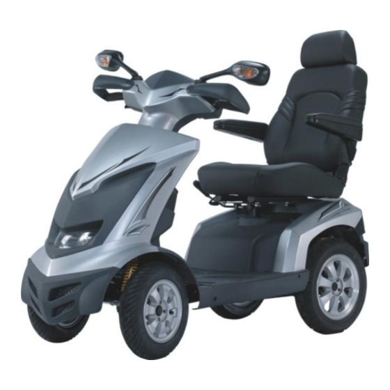
MAJOR ASSEMBLY Your power scooter is shipped partially disassembled for protection during shipping. After unpacking, please check whether you have received the following main components as our standard specification (See Fig.1). 1. Scooter (without seat) 2. Captain Seat (Fig. 1) -
Page 5: Safety Instruction
SAFETY INSTRUCTION OPERTATION OF SCOOTER 1. To prevent injury to yourself or others, always ensure that the power is switched off when getting on or off of the scooter. 2. Always check that the drive wheels are engaged (drive mode) before driving. Engaged position (Fig.2) - Page 6 Ramps and Curbs 1. Also check that ramp surface is roughened to prevent slipping. Never drive across a slope or turn sharply on a slope. When driving up or down ramps, be sure to check that the angle of the slope is less than 10 degrees (slopes about 1/6).
-
Page 7: Warranty.
(3) The function of the Micro-switch Brake System in the scooter. When transferring at free-wheel condition, a brake system will appear if the transferring speed is more then 30% of the scooter’s maximum speed. (Fig.9) General 1. Always use a seat belt, and keep your feet on the scooter all the time. 2. - Page 8 PT7 and PF7. Motorized scooters may as susceptible to electromagnetic interference (EMI), which is interfering electromagnetic energy emitted from sources such as radio stations, TV stations, amateur radio (HAN) transmitter, two-way radios and cellular phones. The interference (from radio wave sources) can cause the powered wheelchair to release its brakes, move by itself or move in unintended directions.
-
Page 9: E N V I R O N Me N T C O N D I T I O N
ENVIRONMENTAL CONDITIONS Environmental conditions may affect the safety and performance of your power scooter. Water and extreme temperatures are the main elements that can cause damage and affect performance. A) Rain, Sleet and Snow If exposed to water, your power scooter is susceptible to damage to electronic or mechanical components. -
Page 10: Wa R R A N T
WARRANTY Quality/ Warranty Declaration Products are to be fit for purpose and of excellent quality and performance. For valid warranty claims Heartway will, at their discretion, replace/ repair/ refund items mutually agreed to be defective. Heartway’s warranty as following: (1) Frame: two year limited warranty (2) Electronic Components and Charger: one year limited warranty. -
Page 11: Assembly Instruction
ASSEMBLY INSTRUCTION It is very easy to assemble your PT7 scooter. Please follow the procedure below . 1. Tiller Positioning Press down the lever, fold the tiller up to vertical position and let it lock into your preferred position. (See Fig 2) - Page 12 6. Installing the Batteries (y ou can omit this step if your scooter already assembled with the batteries) Release the screw Lift off the shroud from nuts with your hand. the base frame gently (Fig.12) (Fig.13) Connected ﹢/ ﹣ pole (Red is positive, black is negative) Connect each battery harness ring terminal to the batteries...
-
Page 13: Adjustment For Seating Comfort
ADJUSTMENTS FOR SEATING CONFORT A. Armrest Position Adjustment Turn the round plate and adjust to your position. Anticlockwise will move the armrest upward and clockwise will be downward Fig.14) B. Seat Rotation and Position Adjustment B-1: Seat Rotation Adjustment → press down the seat rotation lever →... - Page 14 B-2: Seat Position Adjustment → lift up the seat position lever → slide your seat backward or forward to your desired position → let the lever lock into your preferred position.(See Fig 16) Note: The distance of adjustment from backward to forward is 150mm. (Fig 17) C.
- Page 15 Press the button (Fig 19)
-
Page 16: Specification Of Control Panel
OPERATION AND CONTROL PANEL SCOOTER CONTROL PANEL (LCD) SPECIFICATIONS FOR:JSC501(LCD) APPR PREPD DATE TEST DESN NAME: Updated 070829 Scooter Control Panel (LCD) Functions DWG NO: New Spec. 061012 REVISION DATE CHK JSC501 RECORD... - Page 17 INDEX 1. A P P E A R A NC E … … … … … … … … … … … … … … … … … … … … … . .1 8 2. FUNCTIONS…………………………………………………………..19~20 2-1. Function Descriptions……………………………………………….19 2-2.
-
Page 18: Led Indication
1. APPEARANCE LCD(Liquid Crystal Display)Scooter Control Panel, TN Mode Buttons Function LED Indication Buttons... - Page 19 2. FUNCTIONS 2-1 Function Descriptions SPECIFICATION FUNCTION 7 Segment display (2.5 digits +1 decimal) + “km/h / mph” symbol Speed Sensor High / Low / Turn Indicated as “H” and “L” symbols Speed Battery remaining capacity and charging indicator Power Indicator (6 squares + Battery Icon) Hour / Minute / Second display and setting Clock...
- Page 20 2-2 Button & LED FUNCTION SPECIFICATION “MODE” switch Function set Right-Indicator control Left-Indicator control Buttons Parking Light control Headlight control High / Low speed switch Back-up lamps control Horn Left-Indicator (Green) Right- Indicator (Green) LED Indicators Parking (Red) Headlight (Blue) Warning (Red) Back-up lamp (Amber) Illumination: 700 mcd min (Orange color)
- Page 21 4. Characteristics Test General Characteristic Performance Test (20 5℃) Hardware Circuit: ITEM SPECIFICATION RESULT (n = ) Lowest Operation 16V max Voltage Dynamic: 200 mA max -- Backlight and LED light status Consuming Current Static: 5 mA max = 24.0V) -- Key OFF status 5.
- Page 22 5-2. High / Low / Turn Speed ITEM SPECIFICATION (1) Switch High / Low speed by pressing button once. (TRN as control signals) Press one time: High-speed <<--->> Low-speed Operation Features (with memory storage). (2) Take exterior turn-switch as determinant signal (TRN as control signals).
- Page 23 5-3. Power Indication ITEM SPECIFICATION Remaining Voltage (V) Scale Bar Capacity (%) > 25.42 ≦ 25.42 ≦ 25.12 Battery Remaining Capacity ≦ 24.78 ≦ 24.42 ≦ 23.88 Flashing Low-power Warning LED Flashing Warning Flicker 2 sec. Frequency (1) Scale status only decrease, won’t increase. (2) When the remaining capacity was less than 30%, warning sound Operation (“Be-Be”...
- Page 24 ITEM SPECIFICATION Remaining Voltage Scale Bar Capacity (%) < 25.44 > 25.44 > 26.18 Charge Indication > 26.92 > 28.5 Increase 0.5 sec. Frequency (1) Scale status only decrease, won’t increase. Operation (2) Take the PIN3(CH3) of charger as determinant signal, enter「Charging Character Mode」when CH3 grounding (L), not only “KEY ON”...
- Page 25 5-4. Clock ITEM SPECIFICATION Tolerance (per day) ±2 sec. 『Hour:Min』mode :『AM 12:00』 Initial Setting Value Display range : AM12:00 ~ PM11:59 『Hour : Min』Setting (12-Hour format) When『Hour』is between 1 and 9 o’clock, displayed at 1~9. 5-5. Odometer ITEM SPECIFICATION Odometer detected by the signal of Opto Coupler then converts into Operation Features distance.
- Page 26 5-6. Headlight Control ITEM SPECIFICATION Take exterior headlight switch as determinant signal. (1) Switch on/off the head light by pressing button once, Operation Feature then LED will turn on/off simultaneously. (2) LCD backlights turn on / turn off with head light. When motor stop, the modulation down to 30% (Headlight) Power Saving Mode When motor act, 100% output power (Headlight)
- Page 27 5-7. Back-up Lamp Control ITEM SPECIFICATION Take exterior back-up lamp switch as determinant signal. (1) Switch on/off the head light by pressing button Operation Feature once, then LED will turn on/off simultaneously. (2) LCD backlights turn on / turn off with head light. When motor changes from act (go forward) to stop, the lamp (Control Mode) reinstated after flashing for 3 sec.
- Page 28 5-8, 9, 10. Indicators and Parking-Lamp Control ITEM SPECIFICATION Take exterior left-right indicators and parking-lamps switch as Operation Feature the determinant signal. Press button once, the right-indicator and turn off, left-indicator flashing, warning sound act. Press again to turn off left-indicator. Control Mode (Left-direction lamp) Press button...
- Page 29 5-11. Malfunction Message ITEM SPECIFICATION Take the connector pin (KEY) of controller as determinant signal, Operation Feature then converts it into digital code. When the controller send out an error message, red LED flashing with controller signal at same time, the “Error message code” will show on LCD.
- Page 30 5-13. Temperature meter (TEMP) ITEM SPECIFICATION Temperature detected by temperature sensor (NTC) from Operation Feature transformation with signal. 2C Tolerance -20C ~50C Display Range -4F ~122F When display C, degree stand for Celsius thermometer Display Switch When display F, degree stand for Fahrenheit thermometer Button 5-14.
- Page 31 5-15. Adjust Buttons ITEM SPECIFICATION “MODE” Function set Button switch General Display Press SET for 3 seconds to reset TRIP at “00.0”. Mode (TRIP) Press MODE and SET simultaneously for more than 2 seconds. to enter “Setting Mode”, then 『Hour:MIN』 start flashing.
- Page 32 5-16. LCD Backlight ITEM SPECIFICATION When pressing MODE and SET buttons, the backlight will be turned on voluntarily and turned off No any operation of ADJ LCD Backlight button more than 5 sec. 6. System Configuration ITEM SPECIFICATION Ds162K01 Series Controller Charger CTE 8A...
- Page 33 BATTERIES & CHARGER BATTERY We recommend that you use deep-cycle batteries that are sealed and maintenance- free for your power scooter. Both sealed lead-acid ( SLA) and gel cell are deep- cycle batteries and are similar in performance. Deep-cycle batteries are specially designed to provide power, drain down, and then accept a relatively quick recharge.
- Page 34 (voltage >28.19V) (voltage > 27.82V) (voltage >27.45V) (voltage > 25.71V) (voltage < 25.71V) * Recharge battery only when the key is in off position. When indicator is showing low status, this confirms battery needs recharge. Note: →Always charge your batteries in well ventilated areas. →The charger is intended for indoor use only.
-
Page 35: Battery Charger Instruction
Battery Charger Instruction 1.APPEARANCE Power Cord Output Plug to Battery Indicator : Green Flash : Power On Orange Flash : Pre Charge Orange : Charging Green&Orange Flash : Charged 80% Green : Full Charge Red Flash:Defect Important! Make sure voltage input is correctly selected for your location (110V or 220V) and adjust manually. -
Page 36: Charger Instruction
Operating Humidity 20% ~ 85 % Measure L 185mm×W 130mm×H 195mm Weight 1.7K g Color Blue 3. CHARGER OPERATING INSTRUCTION (1)Make sure the battery charger output voltage is the same as the connecting battery. (2)Plug in the power cord. LED indicates green flash when AC power on. (3)Connect the battery charger to the battery. - Page 37 9. EMC statements This portion of the content will provide the user with basic information that describes the problems with EMI, known sources of EMI, protective measures either to lessen the possibility or exposure or to minimize the degree of exposure, and suggested action should unexpected or erratic movement occur.
- Page 38 The sources of radiated EMI can be broadly classified into three types: 1. Hand-held portable transceivers ( transmitter-receivers with the antenna mounted directly on the transmitting unit. Examples include: citizens band (CB) radios, “ walkie talkie”, security, fire, and police transceivers, cellular telephones and other personal communication devices.
-
Page 39: Important Information
chance of unintended brake release or powered vehicle movement, which could result in serious injury. 1. Do not operate hand-held transceivers-receivers), such as citizens band (CB) radios, or turn ON personal communication devices, such as cellular phones, while the powered vehicle is turned ON; 2. - Page 40 Assembling drawing SIDE COVER R LOCATOR FRONT TILLER COVER SPEED METER REAR COVER TILLER FRAME FRONT HUB PLUG(R,L) BUZZER DISK BRAKE SET FRONT TYRE RUBBER DUST COVER BEARING TILLER RAM MECHANISM TRANSAXLE SUSPENSION BRACKET HANDEL CAP FRONT AXLE HANDEL GRIP CHARGER REAR HUB FR COVER...
- Page 41 Assembling drawing SIDE COVER R TURNING COUPLING FRONT TILLER COVER SPEED METER REAR COVER TILLER FRAME FRONT HUB PLUG(R,L) BUZZER FRONT TYRE DISK BRAKE SET RUBBER DUST COVER TILLER RAM MECHANISM BEARING TRANSAXLE HANDEL CAP FRONT AXLE(R,L) SUSPENSION BRACKET HANDEL GRIP CHARGER REAR HUB FR COVER...
-
Page 42: Battery Warning
WARNING!! 1) Please beware once the bi-bi sounds alarm to indicate the status of low battery. Conservatively speaking, the mobility is able to reach the maximum traveling distance up to 10 kilometer once the bi-bi sounds exist. Please understand we don’t recommend the user to continue riding once the status of low battery is shown.
Need help?
Do you have a question about the PT7 and is the answer not in the manual?
Questions and answers