Table of Contents
Advertisement
Advertisement
Table of Contents

Subscribe to Our Youtube Channel
Related Manuals for Livestrong LS9.9IC


Summary of Contents for Livestrong LS9.9IC
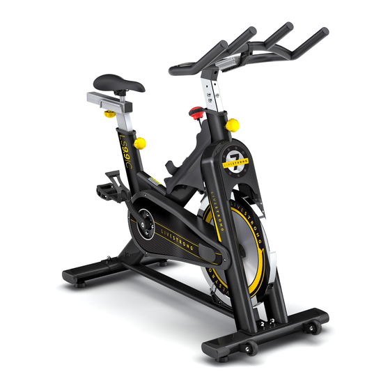
- Page 1 9.9IC INDOOR CYCLE OWNER’S MANUAL...
-
Page 3: Important Precautions
IMPORTANT PRECAUTIONS SAVE THESE INSTRUCTIONS When using an exercise product, basic precautions should always be followed, including the following: Read all instructions before using this indoor cycle. It is the responsibility of the owner to ensure that all users of this indoor cycle are adequately informed of all warnings and precautions. - Page 4 • Use this cycle for its intended purpose as described in this manual. Do not use attachments that have not been recommended by the manufacturer. • Never operate the cycle if it is not working properly, or if it has been damaged. Contact Livestrong Fitness or the authorized dealers for examination and repair.
- Page 5 ENTER YOUR SERIAL NUMBER IN THE BOX BELOW: SERIAL NUMBER: HORIzON LS9.9IC INDOOR CyCLE MODEL NAME: » Refer to the SERIAL NUMBER and MODEL NAME when calling for service.
-
Page 6: Pre-Assembly
LS9.9IC PARTS INCLUDED PRE ASSEMBLY TOOLS NEEDED fOR ASSEmbLy: F Wrench: 17/19mm, 13/15mm, F Allen Wrench: 3mm, 6mm Computer Console Emergency Brake & Resistance Knob Handlebar NEED HELP? Saddle If you have questions or if there are any missing parts, contact Customer Tech Support. -
Page 7: Assembly Step 1
ASSEMBLY STEP 1 & 2 Identify the Rear Stabilizer. While a Support the Front Stabilizer while a second person lifts the rear of the second person lifts the front of the frame, attach the Rear Stabilizer Frame. Attach the Front Stabilizer to to the Frame with two M10 x the Frame with two M10 x 60mm Bolts, 60mm Bolts, four M10 Washers,... -
Page 8: Assembly Step 3
ASSEMBLY STEP 3 & 4 STOP mARk Turn the rear Adjustment Knob counter Mount saddle to the horizontal saddle post as clockwise and pull the adjustment knob to insert shown above. Finally, firmly retighten the saddle the Saddle Post into the Frame. Next, bring mounting clamp and make sure that the saddle the Saddle Post to the desired height, release is mounted in its most horizontal position at the... -
Page 9: Assembly Step 5
ASSEMBLY STEP 5 & 6 Do not over tighten the connecting bolts. Make sure the pop pin adjustment knob is fully engaged and the Handlebar Post does not slide while riding. Connect the 2 ends of the sensor Slide upper part of the handlebar into the handlebar stem and cable. -
Page 10: Assembly Step 7
ASSEMBLY STEP 7 & 8 Mount the computer console the handlebar by Connect the 2 cables reaching out of the sliding it onto the bracket. handlebar to the appropriate sockets on the bottom side of the computer console. Connect the cable with the red marking with the red marked socket. -
Page 11: Assembly Step
ASSEMBLY STEP 9 Identify the Right Pedal. Using a 15mm pedal wrench, firmly tighten the Right Pedal clockwise into the Right Crank Arm. Repeat the same procedure for the Left Pedal but in a counter Clockwise motion. make sure that all parts are properly tightened and that the brake pad is thoroughly soaked with lubricant before the indoor cycle is used. - Page 12 INDOOR CYCLE OPERATION LS9.9IC SPECIfICATIONS TECHNICAL DATA Frame High-tensile, corrosion-resistant frame Resistance Technology Friction brake with microadjust knob and emergency stop Resistance Levels Infinitely variable with linear increase throughout resistance range Drive System Hyper smooth chain wheel system Flywheel 20 kg / 44 lbs.
-
Page 13: How To Adjust The Indoor Cycle
HOw TO ADjUST THE INDOOR CyCLE The Indoor Cycle can be adjusted for maximum comfort and exercise effectiveness. The instructions below describe one approach to adjusting the Indoor Cycle to ensure optimal user comfort and ideal body positioning; you may choose to adjust the Indoor Cycle differently. -
Page 14: Saddle Height Adjustment
SADDLE HEIgHT ADjUSTmENT Proper horizontal adjustment of the saddle is very important in avoiding injury to the knees. Sit on the saddle and move the pedals until the crank arms are in horizontal position. Using your forward most leg as a marker, your kneecap should be directly above the center of the pedal so that a straight line is created between knee and center of the pedal (see the dotted line in image below). -
Page 15: Resistance Adjustment
RESISTANCE ADjUSTmENT The preferred level of difficulty in pedalling (resistance) can be regulated in fine increments by use of the resistance knob. To increase the resistance, turn the resistance knob clockwise. To decrease the resistance, turn the knob counter clockwise. ImPORTANT: To stop the flywheel (wheel) while pedalling, push down on the red brake knob. -
Page 16: How To Move The Indoor Cycle
HOw TO mOVE THE INDOOR CyCLE Due to the weight of the Indoor Cycle, it is recommended that two persons move it. While one person lifts the back of the indoor cycle, the second person firmly holds the handlebar and tips the indoor cycle forward until it rolls on the wheels. Carefully move the Indoor Cycle to the desired location and then lower it. -
Page 17: Specifications
SPECIfICATIONS: TIME…………….. 00:00-99:59 Heart rate …………40-240BPM CNT/MIN…………0-9999 CALORIES (CAL)………0.0-9999KCAL COUNT (CNT)…...0-9999 kEy fUNCTION: SELECT: This key lets you select and lock on to a particular function you want. RESET: Reset the value to zero by pressing the key. OPERATION PROCEDURES: AUTO ON / Off The system turns on when any key is pressed or when it receives an input from the speed sensor. -
Page 18: Weekly Maintenance
mAINTENANCE Regular maintenance must be performed on the Indoor Cycle for optimal performance and longevity. Please read and follow all instructions below. If the Indoor Cycle is not maintained as described, components may wear excessively and the Indoor Cycle may become damaged. -
Page 19: Bi-Weekly Maintenance
bI-wEEkLy mAINTENANCE 1. (Picture right) The Indoor Cycle should not be used if the Emergency Brake System is not working properly. While sitting on the saddle and pedalling, test the brake by pushing down the brake knob. The flywheel should come to a quick and complete stop. belt driven bike Important: A loose belt as well as an over-tightened belt will cause damage to the belt and drive system. -
Page 21: Limited Home Use Warranty
1 year from the date of the • Any attempt to repair this equipment creates a risk of injury. Livestrong Fitness is not original purchase, so long as the device remains in the responsible or liable for any damage, loss or liability arising from any personal injury possession of the original owner. - Page 22 Additional product information is available on phone, email or our website. our website. www.livestrongfitness.com Livestrong fitness 1600 Landmark Drive, Cottage grove wI, 53527 LS9.9IC Rev. 1.0 | © 2009 Livestrong Fitness | Designed & Engineered in the U.S.A. | Made in China...
Need help?
Do you have a question about the LS9.9IC and is the answer not in the manual?
Questions and answers
How I can update it, The, computer monitor
To update the Livestrong LS9.9IC computer monitor, if the screen does not turn on, remove and install new or recharged batteries. No other update process is described.
This answer is automatically generated