Table of Contents
Advertisement
Quick Links
NOTE:
Please read all instructions
carefully before using this
product
Table of Contents
Safety Notice
GB-7000AP Recumbent Bike
Parts Drawing
Screws Pack & Tools
Assembly Instruction
Computer Instruction
Warranty
Ordering Parts
Model
GB-7000AP
Retain This
Manual for
Reference
Dec. 11, 2001
IMPEX FITNESS PRODUCTS
14777 Don Julian Rd., City of Industry, CA 91746
OWNER'S
Tel: (800) 999-8899
Fax (626) 961-9966
www.impex-fitness.com
MANUAL
info@impex-fitness.com
Advertisement
Table of Contents

Related Manuals for Impex Iron Grip Sport GB-7000AP


Summary of Contents for Impex Iron Grip Sport GB-7000AP
- Page 1 NOTE: Please read all instructions carefully before using this product Table of Contents Safety Notice GB-7000AP Recumbent Bike Parts Drawing Screws Pack & Tools Assembly Instruction Computer Instruction Warranty Ordering Parts Model GB-7000AP Retain This Manual for Reference Dec. 11, 2001 IMPEX FITNESS PRODUCTS 14777 Don Julian Rd., City of Industry, CA 91746...
-
Page 2: Table Of Contents
FITNESS TIPS...14 WARRANTY...18 ORDERING PARTS...…..18 BEFORE YOU BEGIN Thank you for selecting the IRON GRIP SPORT GB-7000AP Recumbent Bike by IMPEX FITNESS PRODUCTS. For your safety and benefit, read this manual carefully before using the machine. As a manufacturer, we are committed to provide you complete customer satisfaction. -
Page 3: Important Safety Notice
PHYSICIAN. THIS IS ESPECIALLY IMPORTANT FOR INDIVIDUALS OVER THE AGE OF 35 OR PERSONS WITH PRE-EXISTING HEALTH PROBLEMS. READ ALL INSTRUCTIONS BEFORE USING ANY FITNESS EQUIPMENT. IMPEX INC. ASSUMES NO RESPONSIBILITY FOR PERSONAL INJURY OR PROPERTY DAMAGE SUSTAINED BY OR THROUGH THE USE OF THIS PRODUCT. -
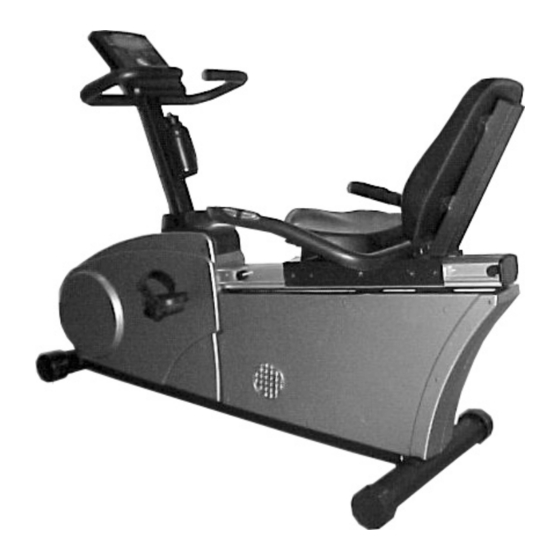
Page 4: Parts Drawing
PARTS DRAWING: DESCRIPTION MAIN FRAME FRONT HANDLE COMPUTER POST COMPUTER SEAT BRACKET SEAT BACKREST BOARD REAR HANDLE SEAT ADJUST KNOB RUBBER CUSHION Q'TY DESCRIPTION 1 PCE PEDAL STRAP (L) 1 PCE PEDAL (L) 1 PCE PEDAL STRAP (R) 1 PCE PEDAL (R) 1 PCE REAR STABILIZER... -
Page 5: Screws Pack & Tools
SCREW PACK & TOOLS: Following are the nuts and bolts needed to assembly the machine. Before start assembling, please check the quantity to make sure all included. -
Page 6: Assembly Instruction
ASSEMBLY: STEP 1: Attach the REAR STABILIZER (#15) to the MAIN FRAME (#1). Securely tighten it with two CARRIAGE BOLTS, WASHERS AND NUTS. STEP 2: Insert the computer sensor wire and hand pulse sensor wire from the MAIN FRAME (#1) through the COMPUTER POST (#3). - Page 7 STEP 4: Use the screwdriver to remove the two Bottle Frame screws on the COMPUTER POST (#3). STEP 5: Attach the BOTTLE FRAME (#19) onto the COMPUTER POST (#3) and securely tighten it with the two screws. Place the WATER BOTTLE (#18) into the BOTTLE FRAME.
- Page 8 STEP 7: Connect the computer sensor wire and hand pulse sensor wire to the jack on the back of the COMPUTER. Attach the COMPUTER (#4) onto the COMPUTER POST (#3) and securely tighten it with the four screws. STEP 8: Attach the FRONT HANDLE (#2) onto the back of COMPUTER POST (#3).
- Page 9 STEP 10: Slide the SEAT BRACKET (#5) onto the aluminum track on the MAIN FRAME (#1). Attach the BACKREST BOARD (#7) to the SEAT BRACKET at the front. Then attach the BACKREST BOARD COVER to the SEAT BRACKET at the back. Align the four holes and secure them with four ALLEN KEY BOLTS.
- Page 10 STEP 13: Pull the hand pulse sensor wire out from the end of the aluminum track on the MAIN FRAME (#1). STEP 14: Attach the REAR HANDLEBAR (#8) to the SEAT BRACKET (#5). Securely tighten it with four ALLEN KEY BOLTS. STEP 15: Locate a Hook attached to the end of the aluminum track.
- Page 11 STEP 17: Push two RUBBER CUSHIONS (#10) into both side of aluminum track on the MAIN FRAME (#1). STEP 18: Plug the END CAP (#17) into the opening on the end of aluminum track. STEP 19: Attach the LEFT PEDAL STRAP (#11) to the LEFT PEDAL (#12) (Both Marked “L”).
-
Page 12: Computer
COMPUTER INSTRUCTION MANUAL A. POWER UP: 1. Install four UM-2 or R14 batteries into the battery case on the back of monitor. Batteries must be installed in sequence and be correctly positioned according to the polarity. 2. If the power source is lower than 2.6V, the low battery indicator on the screen will remind you to replace with new batteries. - Page 13 1.DETAIL OPERATION OF PROGRAM 1 TO PROGRAM 10: A. To enter the initial mode, press and hold the START / STOP key for 2 seconds. B. Press + or - key to choose the exercise program you prefer. The profile will be displayed on the screen.
- Page 14 D. TECHNICAL NOTES: 1. The PULSE rate will be displayed after detecting 4 stable pulse signals. 2. Each pulse is a signal and will be accompanied with one "♥" symbol flashing. 3. If no PULSE detected for over 8 seconds, the CPU will turn off the pulse circuit automatically. This is a power saving measure and you can press START / STOP key to restart the pulse function.
-
Page 15: Fitness Tips
FITNESS TIPS CONSULT YOUR PHYSICIAN Before using this product, please consult your personal physician for a complete physical examination. Your doctor should approve frequent and strenuous exercise. If any discomfort should result from your use of this product, stop exercising and consult your doctor. - Page 16 Exercising in your target zone How fast should your heart beat during aerobic exercise? Fast enough to reach and stay in its “target zone”, a range of beats per minute that is largely determined by our age and physical condition. To determine your target zone, consult the chart we provide.
-
Page 17: Inner Thigh Stretch
Side stretches Open your arms to the side and continue lifting them until they are over your head. Reach your right arm as far upward toward the ceiling as you can for one count. Feel the stretch up your right side. Repeat this action with your left arm. Quadriceps stretch With one hand against a wall for balance, reach behind you and pull your right foot up. -
Page 18: Weight Training
Calf/Achilles stretch Lean against a wall with your left leg in front of the right and your arms forward. Keep your right leg straight and the left foot on the floor. Then bend the left leg and lean forward by moving your hips toward the wall. -
Page 19: Warranty
No other warranty beyond that specifically set forth above is authorized by IMPEX. IMPEX is not responsible or liable for indirect, special or consequential damages arising out of or in connection with the use or performance of the product or other damages with respect to any economic loss, loss of property, loss of revenues or profits, loss of enjoyments or use, costs of removal, installation or other consequential damages or whatsoever natures.
Need help?
Do you have a question about the Iron Grip Sport GB-7000AP and is the answer not in the manual?
Questions and answers