AGA DC3 Installation Manual
Hide thumbs
Also See for DC3:
- User's manual & installation instructions (48 pages) ,
- User instruction (24 pages) ,
- Installation manual (24 pages)
Table of Contents
Advertisement
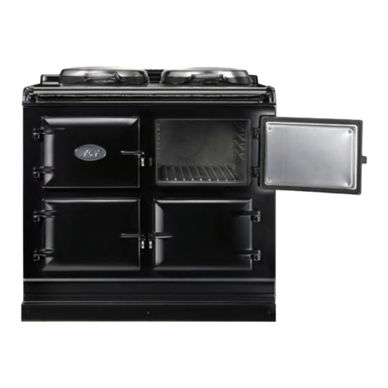
AGA DUAL CONTROL
Model No's: DC3 & DC5
(Includes External Vent &
Room Vent Option)
Installation
Guide
REMEMBER: when replacing a part on this appliance, use only spare parts that
you can be assured conform to the safety and performance specification that we
require. Do not use reconditioned or copy parts that have not been clearly
authorised by AGA.
PLEASE READ THESE INSTRUCTIONS BEFORE COMMENCING SITE SURVEY
OR INSTALLING THIS APPLIANCE.
For use in GB and IE
11/13 EINS 516637
Advertisement
Table of Contents

Related Manuals for AGA DC3


Summary of Contents for AGA DC3
- Page 1 AGA DUAL CONTROL Model No’s: DC3 & DC5 (Includes External Vent & Room Vent Option) Installation Guide REMEMBER: when replacing a part on this appliance, use only spare parts that you can be assured conform to the safety and performance specification that we require.
-
Page 2: Table Of Contents
DELIVERY REQUIREMENTS APPLIANCE DIMENSIONS - AGA DC3 APPLIANCE DIMENSIOSN - AGA DC5 CLEARANCES TOP PLATE ADJUSTMENT - AGA DC3 POWER SUPPLY - AGA DC3 POWER SUPPLY - HOTCUPBOARD (AGA DC5) MAINS CABLE ROUTING - AGA DC3 MAINS CABLE ROUTING - AGA DC5... -
Page 3: Health & Safety
Any alteration that is not approved by AGA could invalidate the approval of the appliance, operation of the warranty and could also affect your statutory rights. In the interests of safety and effective use, please read the following before using your new AGA appliance. -
Page 4: Appliance Dimensions - Aga Dc3
10mm beyond the figures quoted above. This allows safe margin to take into account the natural dimensional variations found in major castings. In particular the width across the appliance recess could be critical. APPLIANCE WEIGHT (Excludes Packaging) Model: AGA Dual Control (DC3) - 444kg... -
Page 5: Appliance Dimensiosn - Aga Dc5
10mm beyond the figures quoted above. This allows safe margin to take into account the natural dimensional variations found in major castings. In particular the width across the appliance recess could be critical. APPLIANCE WEIGHT (Excludes Packaging) Model: AGA Dual Control (DC3) - 444kg Hotcupboard - 110kg... -
Page 6: Clearances
It is essential that the base or hearth on which the cooker stands should be level and be capable of supporting the total weight of the appliance. The base of the built-in AGA plinth must be level and sit above finished floor height for service access. -
Page 7: Top Plate Adjustment - Aga Dc3
Top Plate Adjustment - AGA DC3 (See Fig. 3) In general, adjustment of the top plate is to be avoided. However minimum use of the top plate adjusters can be used to improve the alignment of the top plate. Fig. 3... -
Page 8: Power Supply - Aga Dc3
POWER SUPPLY - AGA DC3 WARNING: THIS APPLIANCE MUST BE EARTHED. THIS APPLIANCE IS DESIGNED FOR THE VOLTAGE STATED ON THE RATING PLATE, WHICH IS SITUATED BEHIND THE PLINTH COVER. A 1PH 32 amp 230V or 3PH 400V minimum 16A per phase ~ 50 Hz fused electrical supply is required adjacent to the appliance. -
Page 9: Mains Cable Routing - Aga Dc3
MAINS CABLE ROUTING - AGA DC3 MAINS CABLE FED FROM CONTROL TRAY LEFT OR RIGHT EXIT THROUGH DUCTING DEPENDENT UPON POSITION OF SUPPLY SOCKET Fig. 4 DESN 516643 THE MAINS SUPPLY CONNECT POINT MUST BE WITHIN THE ZONES SHOWN Fig. 4A... -
Page 10: Mains Cable Routing - Aga Dc5
MAINS CABLE ROUTING - AGA DC5 (HOTCUPBOARD OPTION) HOTCUPBOARD POWER SUPPLY MAINS CABLE FED FROM CONTROL TRAY LEFT OR RIGHT EXIT THROUGH DUCTING DEPENDENT UPON POSITION OF SUPPLY Fig. 5 DESN 516644 SOCKET THE MAINS SUPPLY CONNECT POINT MUST BE WITHIN THE ZONES SHOWN Fig. -
Page 11: External Vent Models - Vent Pipe Connection
Reseal pipe connection with aluminium tape. When installing a AGA DC5 which is venting to the left hand side, care must always be taken to ensure the vent pipe is fully lagged (using insulation provided). Where the vent pipe passes behind the hotcupboard, ensure that the mains cable is kept away from the hot surface of the vent pipe. -
Page 12: Room Vented Models
It is recommended that this model is fitted in conjunction with a cooker hood. The AGA oven venting outlet is located on the top of the AGA between the two hotplates., and is designed for venting the moisture from the ovens. The cooker hood should be positioned not less than the minimum height as recommended by the manufacturer, from the top of the AGA. -
Page 13: Oven Venting Systems
OVEN VENTING SYSTEMS See Fig. 8 The appliance oven venting pipe can be achieved up to a maximum length of 6 metres, through an outside wall. Great care must be taken in all-timber houses. If the oven vent pipe passes through combustible material, there must be an air gap of at least 25mm around the pipe and preferably wrapped with insulation material. -
Page 14: Hotcupboard Installation
NOTE: The AGA DC5 hotcupboard should arrive with the top plate in a jacked up position. This is to allow the complete appliance to be slid onto its plinth when alongside the AGA DC3 without the top plates clashing. The hotcupboard top plate should then be wound down to its correct height once the appliance is in its final position. - Page 15 2. Position the plinth alongside the AGA Dual Control leaving no gap between the two plinths (See Fig. 11). Check with a spirit level that the plinth level is correct, and also check height differential between the hotcupboard plinth and Dual Control plinth is correct (11mm). If necessary, use shims in each corner to level the plinth.
- Page 16 4. Run a straight edge along the front of the AGA Dual Control plinth, to ensure the front face of both plinths sit squarely against the straight edge. (See Fig. 13) When satisfied both plinths sit squarely, jacking screws can be tightened until they just make contact with the AGA Dual Control plinth, and locking screws can now be tightened.
- Page 17 Fig. 15 DESN 516552 7. The hotcupboard top plate is set 5mm higher than the AGA Dual Control top plate. This is to prevent damage to the enamel during installation. Lower the top plate using the adjusters (See Figs. 16 & 17).
- Page 18 9. Slide the complete handrail over the left hand, right hand and centre fixing studs. Once the assembly has been fitted to the AGA appliance, fit the handrail endcaps (ensuring the handrail is evenly spaced at each end). The endcaps should be carefully pushed into place until they sit flush with the outside face of each bracket.
-
Page 19: Handrail Connection - Aga Dc3
HANDRAIL CONNECTION - AGA DC3 Fig. 19 DESN 516560 Handrail brackets, endcaps and handrail require assembly. Locate endcaps onto handrail, place brackets over endcaps and then slide complete assembly onto locating studs. Once assembly is correctly located, lock into position with grub screws (located on underside... -
Page 20: Wiring Diagram - Aga Dc3
WIRING DIAGRAM - AGA DC3 Fig. 20... -
Page 21: Wiring Diagram - Hotcupboard Option
WIRING DIAGRAM - AGA DC5 (HOTCUPBOARD OPTION) CAUTION: LABEL ALL WIRES PRIOR TO DISCONNECTION, WHEN SERVICING CONTROLS WIRING ERRORS CAN CAUSE IMPROPER AND DANGEROUS OPERATION. VERIFY PROPER OPERATION AFTER SERVICING Fig. 21... -
Page 22: Aga Dual Control Checklist
AGA DUAL CONTROL CHECKLIST SERIAL No. Tick Box Check hotplate lids and settings. Check oven door seals, adjust door alignment if necessary. Baking and Simmering oven rope seals MUST have a gap between the door hinges. The Roasting Oven is fitted with a continuous seal. - Page 24 For further advice or information contact your local AGA Specialist With AGA’s policy of continuous product improvement, the Company reserves the right to change specifications and make modifications to the appliance described and illustrated at any time Manufactured by AGA Rangemaster...
Need help?
Do you have a question about the DC3 and is the answer not in the manual?
Questions and answers