Advertisement
Table of Contents
- 1 Table of Contents
- 1 Equipment Lists
- 2 System Configuration
-
3
Mounting
- 3.1 Display Unit
- 3.2 Thru-Hull Mount Transducer 520-5PSD, 520-5MSD
- 3.3 Transom Mount Transducer 520-5PWD, Optional Transom Mount Triducer 520ST-PWD
- 3.4 Inside-Hull Mount Transducer 520-5PSD, 520-5MSD
- 3.5 Optional Water Temperature/Speed Sensors
- 3.6 Optional Water Temperature Sensors
- 3.7 Optional Triducer 524ST-MSD, 525ST-MSD
- 4 Wiring
- 5 External Equipment Setup
- 6 Appendix Triducer 525St-Pwc/Pwd
- Download this manual
See also:
Operator's Manual
Advertisement
Table of Contents

Related Manuals for Furuno FCV-600L


Summary of Contents for Furuno FCV-600L
- Page 1 Back...
- Page 3 (such as proper installation of the equipment. toluene) since it may harm the sheath. FURUNO will assume no responsibility for any damage associated with improper installation. Be sure that the power supply is compatible with the voltage rating of the equipment.
-
Page 4: Table Of Contents
TABLE OF CONTENTS EQUIPMENT LISTS ..................... iii SYSTEM CONFIGURATION................iv MOUNTING 1.1 Display Unit ........................1 1.2 Thru-hull Mount Transducer 520-5PSD, 520-5MSD............3 1.3 Transom Mount Transducer 520-5PWD, Optional Transom Mount Triducer 520ST-PWD............6 1.4 Inside-hull Mount Transducer 520-5PSD, 520-5MSD............8 1.5 Optional Water Temperature/Speed Sensors ..............11 1.6 Optional Water Temperature Sensors ................12 1.7 Optional Triducer 524ST-MSD, 525ST-MSD ..............14 WIRING... -
Page 5: Equipment Lists
EQUIPMENT LISTS Standard Supply l l a i t a s t r 2 0 0 - , l l , t n Optional Supply i f i h t i r t , l l u h t i , e l l l u l l u... -
Page 6: System Configuration
SYSTEM CONFIGURATION DISPLAY UNIT CV-600L 12-24 VDC TRANSDUCER External equipment Standard supply (GPS navigator, etc.) 520-5PSD 520-5MSD SPEED, TEMPERATURE SENSOR (option) 520-5PWD Speed/temperature sensor Optional supply ST-02MSB (triducer) ST-02PSB 524ST-MSD Temperature sensor 520ST-PWD T-02MTB T-02MSB T-03MSB... -
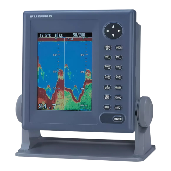
Page 7: Mounting
MOUNTING 1.1 Display Unit Mounting considerations The display unit can be installed on a tabletop or on the overhead. When selecting a mounting location for the display unit keep the following in mind: • Keep the display unit out of direct sunlight. •... - Page 8 Removing cover While pressing the center of the cover with your thumbs as illus- trated, pull the cover towards you to remove it. Mounting procedure Figure 1-2 How to set the display unit to the hanger...
-
Page 9: Thru-Hull Mount Transducer 520-5Psd, 520-5Msd
1.2 Thru-hull Mount Transducer 520-5PSD, 520-5MSD Transducer mounting location This type of mounting provides the best performance of all, since the transducer protrudes from the hull and the effect of air bubbles and turbulence near the hull skin is reduced. When the boat has a keel, the transducer should be at least 30 cm away from it. - Page 10 Acceptable transducer mounting locations Deep-V hull • Position 1/2 to 1/3 length of the hull from stern • 15 to 30 cm off center line (inside first lifting strakes). Figure 1-4 Transducer mounting location on deep-V hull High speed V-planing hull •...
- Page 11 Procedure for installing the thru-hull mount transducer 1. With the boat hauled out of the water, mark the location se- lected for mounting the transducer on the bottom of the hull. 2. If the hull is not level within 15° in any direction, fairing blocks made out of teak should be used between the transducer and hull, both inside and outside, to keep the transducer face paral- lel with the water line.
-
Page 12: Transom Mount Transducer 520-5Pwd, Optional Transom Mount Triducer 520St-Pwd
1.3 Transom Mount Transducer 520-5PWD, Optional Transom Mount Triducer 520ST-PWD This type of mounting is very commonly employed, usually on relatively small I/O or outboard boats. Do not use this method on an inboard motor boat because turbulence is created by the propel- ler ahead of the transducer. - Page 13 M5 x 20 M5 x 20 5° Tape No. 1 M5 x 14 Figure 1-9 Transom mount transducer, mounting flush with hull Installing the transom mount transducer projecting from hull (for deep-V hulls) This method is employed on deep-V hulls and provides good per- formance because the effects of air bubbles are minimal.
-
Page 14: Inside-Hull Mount Transducer 520-5Psd, 520-5Msd
1.4 Inside-hull Mount Transducer 520-5PSD, 520-5MSD Necessary tools You will need the following tools: • Sandpaper (#100) • Silicone sealant • Silicone grease Remarks on installation • Turn off the engine and anchor the boat while installing the equip- ment. •... - Page 15 Attaching the transducer 1. Clean the transducer face to remove any foreign material. Lightly roughen the transducer face with #100 sandpaper. Also, roughen the inside of the hull where the transducer is to be mounted. 2. Warm the silicone sealant to 40°C before usage to soften it. Coat the transducer face and mounting location with silicone sealant.
- Page 16 Checking the installation 1. Connect the battery to the display unit as shown on page 15. 2. Turn on the display unit. 3. Press the MODE key to select NORMAL (if it is not already selected) and press the MENU ESC key. 4.
-
Page 17: Optional Water Temperature/Speed Sensors
1.5 Optional Water Temperature/Speed Sensors Through-hull mount water temperature/speed sensor ST-02MSB, ST-02PSB Select a suitable mounting location considering the following: • Select a mid-boat flat position. The sensor does not have to be installed perfectly perpendicular. The sensor must not be dam- aged in dry-docking operation. -
Page 18: Optional Water Temperature Sensors
1.6 Optional Water Temperature Sensors Transom mount water temperature sensor T-02MTB • Fix the cable at a convenient location with cable clamp. • When the cable is led in through the transom board, make a hole of approx. 17 mm diameter to pass the connector. After passing the cable, fill the hole with a sealing compound. - Page 19 Thru-hull mount water temperature sensor T-02MSB, T-03MSB • Select a mid-boat flat position. The sensor does not have to be installed perfectly perpendicular. The sensor must not be dam- aged in dry-docking operation. • Select a place apart from equipment generating heat. •...
-
Page 20: Optional Triducer 524St-Msd, 525St-Msd
1.7 Optional Triducer 524ST-MSD, 525ST-MSD The triducer is designed for thru-hull mounting. Mounting considerations When selecting a mounting location keep the following points in mind: • Air bubbles and turbulence caused by movement of the boat seriously degrade the sounding capability of the transducer. The transducer should, therefore, be located in a position where wa- ter flow is the smoothest. -
Page 21: Wiring
WIRING 2.1 Wiring All wiring are terminated at the rear of the display unit. DISPLAY UNIT Earth terminal Ext. equip White Black Shield TRANSDUCER BATTERY Figure 2-1 Display unit, rear view Power cable Connect the power cable to the power connector. Connect the leads to the battery (12 or 24 VDC);... - Page 22 Transducer, optional triducer Connect the transducer cable to the XDR connector. Ground Connect the ground wire (KIV 2.0sq, 2m, supplied) to ship’s ground to prevent interference to the picture. Shorten the ground wire as much as possible. For FRP vessels, install a ground plate that mea- sures about 20 cm by 30 cm on the outside of the hull bottom to provide a ground point.
-
Page 23: Connection Of Optional Sensors
2.2 Connection of Optional Sensors Water temperature sensor Connect the transducer cable to the XDR connector. Connect the water temperature sensor (option) or water temperature/speed sen- sor (option) to the XDR connector with the converter connector (Type : 02S4147 , Code No. : 000-141-082,option). MJ-A6SRMD MJ-A10SPF SHIELD... - Page 24 Connect to XDR connector at rear of display unit MJ-A10SPF MJ-A6SRMD MJ-A10SRMD Tape connector with self-vulcanizing tape and then vinyl tape to waterproof connector. Bind tape end with cable tie. Water temp., water temp/speed Transducer connector sensor connector Figure 2-6 Connection of transducer, water temperature sensor, water temperature/speed sensor NMEA data sentences , e r...
-
Page 25: External Equipment Setup
EXTERNAL EQUIPMENT SETUP This chapter shows you how to set up the FCV-600L when exter- nal equipment is connected. If a water temperature/speed sensor is installed, you should complete this section with the boat in the water and running, to confirm speed/water temperature readout. - Page 26 Draft setup 1. At the System menu 1, press to select DRAFT. 2. Press t or s to set draft. For example, if the depth readout is 5 feet lower than actnal depth, enter +5 feet. Navigator setup 1. At the System menu 2, press to select NMEA.
- Page 27 Confirming indications 1. Reset the power. 2. Confirm that appropriate data appears on the display. Speed 22.6°C 12kt 200k Water temperature 35°15.000’N Nav data (position) 135°07.500’E Water temperature scale Water temperature marker (orange) 49.6 Figure 3-2 Location of speed, water temperature and nav data indications...
- Page 28 This page is intentionally left blank.
-
Page 29: Appendix Triducer 525St-Pwc/Pwd
APPENDIX TRIDUCER 525ST-PWC/PWD This appendix provides a copy of the installation instructions for AIRMAR triducer. If you loose the original supplied with the triducer, use this appendix. INSTALLATION INSTRUCTIONS ® Transom Mount Transducer or TRIDUCER Multisensor with Integral Release Bracket Model P66 U.S. - Page 30 APPENDIX TRIDUCER 525ST-PWC/PWD Caution: Never Use Solvents! Installation template Cleaners, gasoline, paint, sealants, and other products may contain strong solvents such as acetone which can attack for starboard side of boat many plastics dramatically reducing their strength. Drill at locations labeled "B" Installation for the following transom angles: Bracket...
- Page 31 APPENDIX TRIDUCER 525ST-PWC/PWD Cable Routing Route the sensor cable over the transom, through a drain hole, or 2°-10° transom angle 11° transom angle 19°-22° transom angle NO SHIM thorough a new hole drilled in the transom above the waterline. shim with shim with taper down taper up...
- Page 32 1.コ-ド番号末尾の[**]は、選択品の代表型式/コードを表します。 CODE NUMBER ENDED BY "**" INDICATES THE NUMBER OF TYPICAL MATERIAL.
- Page 36 *00080822000* *00080822000* *00080822000* *00080822000* ( ( DAMI DAMI ) ) FCV-600L FCV-600L * 0 0 0 8 0 8 2 2 0 0 0 * * 0 0 0 8 0 8 2 2 0 0 0 * *IME23620J30* *IME23620J30*...
Need help?
Do you have a question about the FCV-600L and is the answer not in the manual?
Questions and answers