Sign In
Upload
Download
Add to my manuals
Delete from my manuals
Share
URL of this page:
HTML Link:
Bookmark this page
Add
Manual will be automatically added to "My Manuals"
Print this page
×
Bookmark added
×
Added to my manuals
Manuals
Brands
Reznor Manuals
Gas Heater
VPS Series
Propane conversion instructions
Reznor VPS Series Propane Conversion Instructions
Propane conversion instructions (including high altitude adjustment) applies to: gas-fired, tubular radiant, low-intensity infrared heater
Hide thumbs
1
2
3
4
5
6
7
8
9
10
11
12
13
14
15
16
17
18
19
20
21
22
23
24
page
of
24
Go
/
24
Bookmarks
Advertisement
Quick Links
Download this manual
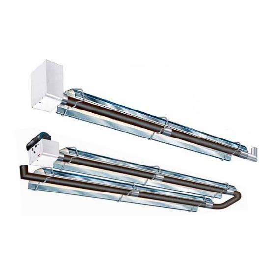
PROPANE CONVERSION INSTRUCTIONS
(INCLUDING HIGH ALTITUDE ADJUSTMENT)
Applies to: Gas-Fired, Tubular Radiant,
Low-Intensity Infrared Heater
Models VPS, VPT, VCS, VCT
Form CP-VC/VP-GC (Version B)
Part no. 270686
Previous
Page
Next
Page
1
2
3
4
5
Advertisement
Need help?
Do you have a question about the VPS Series and is the answer not in the manual?
Ask a question
Questions and answers
Related Manuals for Reznor VPS Series
Heater Reznor VPS Installation & Operation Manual
120v 60hz gas-fired, tubular, radiant, low-intensity infrared heater (44 pages)
Gas Heater Reznor VCS Series Propane Conversion Instructions
Propane conversion instructions (including high altitude adjustment) applies to: gas-fired, tubular radiant, low-intensity infrared heater (24 pages)
Gas Heater Reznor VCT Series Propane Conversion Instructions
Propane conversion instructions (including high altitude adjustment) applies to: gas-fired, tubular radiant, low-intensity infrared heater (24 pages)
Gas Heater Reznor VPT Series Propane Conversion Instructions
Propane conversion instructions (including high altitude adjustment) applies to: gas-fired, tubular radiant, low-intensity infrared heater (24 pages)
Gas Heater Reznor Flamrad Installation, Servicing And Operating Instructions
Gas fired infra-red overhead radiant heaters (12 pages)
Gas Heater Reznor UDXC Installation, Operation And Maintenance Manual
Gas-fired unit heater (64 pages)
Gas Heater Reznor UDSA 008-2 Installation And Servicing Manual
Gas fired balanced flue/fan assisted flue unit heater (36 pages)
Gas Heater Reznor Thomas & Betts UDAP 30 Instructions Manual
Venting instructions for v3 power vented unit heaters (49 pages)
Gas Heater Reznor CD2 Installation
Downturn nozzle kit for gas-fired unit heaters (4 pages)
Gas Heater Reznor UEZ Installation, Operation And Maintenance Manual
Gas-fired unit heater (64 pages)
Gas Heater Reznor UBXC Installation, Operation And Maintenance Manual
Gas-fired unit heater (64 pages)
Gas Heater Reznor PHOTON Series Installation, Commissioning And Servicing Instruction Manual
Gas fired unit heater (52 pages)
Gas Heater Reznor RHC DJL 4000 Series Installation, Commissioning, Servicing
Gas-fired power vented unit heater (27 pages)
Gas Heater Reznor RIHN Installation, Operation And Maintenance Manual
Gas-fired high-intensity infrared heater (56 pages)
Gas Heater Reznor SC Series Instructions For Installing
Replacement gear motor kit, applies: modulating gas control options (4 pages)
Gas Heater Reznor UBX Installation
(4 pages)
This manual is also suitable for:
Vcs series
Vct series
Vpt series
Vpt60
Vpt80
Vpt100
...
Show all
Vpt125
Vpt150
Vpt170
Vpt200
Vcs60
Vcs80
Vcs125
Vcs100
Vcs150
Vcs170
Vct60
Vcs200
Vct80
Vct100
Vct150
Vct125
Vct170
Vct200
Vps 100
Vps 125
Vps 150
Vps 170
Vps 200
Vps 60
Vps 80
Print
Rename the bookmark
Delete bookmark?
Delete from my manuals?
Login
Sign In
OR
Sign in with Facebook
Sign in with Google
Upload manual
Upload from disk
Upload from URL


Need help?
Do you have a question about the VPS Series and is the answer not in the manual?
Questions and answers