USAutomatic Patriot I Installation And Owner's Manual
High quality low voltage vehicular swing gate operator
Hide thumbs
Also See for Patriot I:
- Installation & owner's manual (72 pages) ,
- Installation & owner's manual (76 pages) ,
- Installation & owner's manual (72 pages)
Table of Contents
Advertisement
Quick Links
- 1 Control Board Dipswitch Setting Verification/Operating the Gate
- 2 Programming Transmitter and Receiver/Keypad
- 3 Limit Switch Adjustment
- 4 Limit Switch Adjustment
- 5 Troubleshooting Guide
- 6 Troubleshooting Introduction
- 7 Accessory Wiring Diagrams
- Download this manual
See also:
Installation & Owner's Manual
Advertisement
Table of Contents

Related Manuals for USAutomatic Patriot I


Summary of Contents for USAutomatic Patriot I
- Page 1 PATRIOT USAutomatic High Quality Low Voltage Vehicular Swing Gate Operator Solar or AC Charged PATRIOT I Single Swing Gate Operator PATRIOT II Dual Swing Gate Operator Installation/Owners Manual PROUDLY MADE IN THE USA www.usautomatic.com...
-
Page 3: Introduction
Entrapment zones on page 23-25 and be aware of these areas not only during use but also during any adjustments to the unit. The USAutomatic battery charger is designed to operate with +12 vdc deep cycle batteries rated at 33-amp hour minimum. Gel type or AGM batteries are recommended. -
Page 4: Table Of Contents
Table Of Contents Page Introduction ..................... 1 Table of Contents ..................2 General Requirements/Gate Qualifications & Applications....3 Importance of a Properly Designed Gate ..........4 Mounting Site Review................4 Parts Included List................... 5 Hinge Mount Tube Installation/Pull to Open.......... 6 Hinge Mount Tube Installation/Push to Open/Vertical Height .... -
Page 5: General Requirements/Gate Qualifications & Applications
The actuator harness is equipped with 3/8” ring terminals designed to connect to bolt type battery posts. The USAutomatic charger is designed for this type of battery. Using a smaller amp hour battery may cause damage to the charging system. -
Page 6: Importance Of A Properly Designed Gate
IMPORTANCE OF A PROPERLY DESIGNED GATE As a general rule, an automatically operated gate, must be stronger and smoother than a manually operated gate. Since the gate is a major component of the system, great care and concern must be given to the gate design. A GATE OPERATOR CANNOT OVERCOME A POORLY DESIGNED GATE. -
Page 7: Parts Included List
PARTS INCLUDED *Actuator Arm with 8 foot of Cable Cabinet with Control Board and Receiver Antenna Assembly *Actuator Cable with coax and bracket Strain Relief Clamp Snap in Grommet Solar Panel with Bracket and hardware Battery Solar Panel Charger 1- 2 button * Gate Bracket Transmitter 2”... -
Page 8: Hinge Mount Tube Installation/Pull To Open
STEP 1 Hinge Mount Tube Installation Using the diagrams in Figure 1 below determine the type of installation and gatepost to be used. These diagrams show left hand installation reverse for right hand installation. Figure 2 and 3 show installation for thick wall post. -
Page 9: Hinge Mount Tube Installation/Push To Open/Vertical Height
STEP 2a Hinge Mount Tube Installation (Push to Open Installation Top View) Use dimensions in figure 3 to determine mounting location of Hinge mount tube, cut hinge mount tube as necessary to achieve correct mounting dimension. OPEN DIRECTION Gatepost 4” steel shown ¼”... -
Page 10: Gate Bracket Installation/Pull To Open
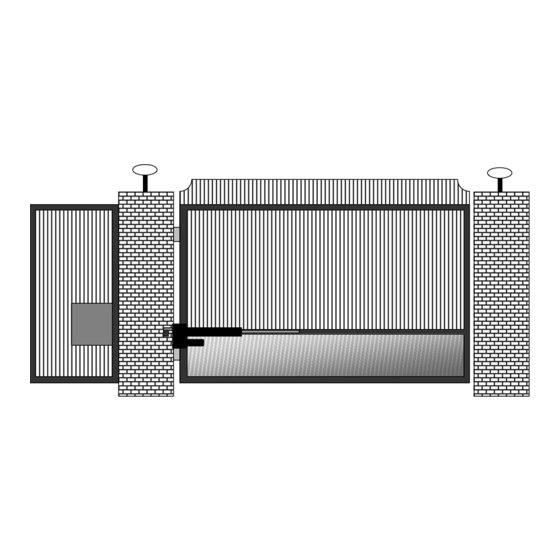
STEP 1 Gate Bracket Installation (Prepare Actuator for Installation) NOTE: Do not operate the actuator before performing all installation steps. There is no need to extend the actuator before all installation steps are complete. If you must operate the actuator ensure that the extension screw does not rotate while operating to avoid possible actuator damage. -
Page 11: Gate Bracket Installation/Push To Open/Diagrams
STEP 4 Gate Bracket Installation (PUSH to Open Only) The actuator is adjusted to the fully retracted or closed position from the factory. Once the actuator is connected to the hinge mount tube, swing the gate to the desired closed position and block in place to secure the gate. -
Page 12: Mounting The Control Box/Splicing Actuator Cable
STEP 5 Mounting Control Box When deciding where to mount the control box remember the actuator cable for the master gate is 8 feet in length. If possible mount the control box in a location that will allow the cable to be neatly routed. Do not splice cable for additional length unless absolutely necessary. -
Page 13: Installation Of Charging Device
Modifying the charger power cord will void the charger warranty. Note: USAutomatic recommends an AC surge protector on all 110-volt AC installations, especially in lightning prone areas. Do not modify the AC cord on the charger. -
Page 14: Connecting Actuator Cable To Control Board
Verify that nothing is in the path of the gate, if by chance it begins to move when power is applied. Be prepared to disconnect the actuator cable, if needed to stop the gate if it begins to move. Patriot I Locate the master actuator cable and plug it into the “Master” actuator connector (see figure 15) on the control board. -
Page 15: Control Board Dipswitch Setting Verification/Operating The Gate
Locate the dipswitches on the Patriot Control board (see page 20). Factory default dipswitch settings are 2 and 3 on. Identify you installation below and verify dipswitch settings: Patriot I (Pull to Open) Patriot I (Push to Open) Dipswitches 2, 3 should be in the on position. -
Page 16: Programming Transmitter And Receiver/Keypad
Step 11 Programming Transmitter and Receiver (model 433DSR2LC) The Transmitter and Receiver provided operate at 433 MHz. Receiver can store up to 22 unique transmitter codes. Transmitter Setup: (It is recommended that the dipswitches be changed from the default setting) 1. - Page 17 STEP 12 Programming wireless Keypad (model 433 KPD) Terms to understand: Master Password – The 5-digit code used to access programming features. Factory default is “11111.” This needs to be changed by the end user for security reasons. Access Code – The 1 to 5-digit code used to open the gate (24 unique codes are possible). If access code is less than 5 digits it requires the # sign after code is entered.
- Page 18 Changing Security Code This keypad has a virtual dipswitch used to create your Security Code. The virtual dipswitch contains nine 3- position switches. The default Security Code has all nine switches in the center position. To ensure neighboring keypads do not interfere with each other, the virtual switches should be positioned in a random pattern, using the following procedure.
-
Page 19: Making Final Adjustments/Installing Antenna Assembly
CAUTION: To reduce the risk of injury, USAutomatic strongly recommends the installation of safety devices such as Photo Eye Sensors, Safety Loops, Safety Edges. Consult an authorized installing dealer or the factory for a complete explanation of options and see the Safety Section... -
Page 20: Limit Switch Adjustment
Limit Switch Adjustment The limit switch adjustments are located on the bottom of the actuator. Remove the dust plug to make adjustments. Flat blade screwdriver is included with the operator. If soft stop is going to be used turn dipswitch 6 or 7 (see page 20) on at this time. Prior to operating the gate the actuator extension tube needs to be turned 6 turns in the counter clockwise direction. -
Page 21: Control Board Terminal Description For Accessories
Circuit Board Terminal Description For Accessories Patriot Control Board MASTER SLAVE Timer USAutomatic MADE IN USA Sensitivity Sensitivity PATRIOT CONTROL BOARD CURRENT SENSE CURRENT SENSE TIMER TO CLOSE ADJUSTMENT ADJUSTMENT ADJUSTMENT ADJUSTMENT DS1 SWITCH SETTINGS FACTORY SETTINGS SW-1 AUTO CLOSE TIMER ENABLE... -
Page 22: Function Of Programming Switch Settings Ds1
DS1 Programming Dipswitches MASTER SLAVE Timer USAutomatic MADE IN USA Sensitivity Sensitivity PATRIOT CONTROL BOARD CURRENT SENSE CURRENT SENSE TIMER TO CLOSE ADJUSTMENT ADJUSTMENT ADJUSTMENT ADJUSTMENT DS1 SWITCH SETTINGS FACTORY SETTINGS SW-1 AUTO CLOSE TIMER ENABLE SW-2 TIMER TO CLOSE WILL ACTIVATE ON LIMIT ONLY... -
Page 23: Function Of Programming Switch Settings Ds2
DS2 Programming Dipswitches MASTER SLAVE Timer USAutomatic MADE IN USA Sensitivity Sensitivity PATRIOT CONTROL BOARD CURRENT SENSE CURRENT SENSE TIMER TO CLOSE ADJUSTMENT ADJUSTMENT ADJUSTMENT ADJUSTMENT DS1 SWITCH SETTINGS FACTORY SETTINGS SW-1 AUTO CLOSE TIMER ENABLE SW-2 TIMER TO CLOSE WILL ACTIVATE ON LIMIT ONLY... -
Page 24: Safety Section
Patriot I and Patriot II gate operators are intended to be installed as Class I or Class II vehicular gate operators, and the maximum load of each gate leaf should not exceed 650 pounds with a length not to exceed sixteen feet. - Page 25 NOTE: USAutomatic recommends that these devices be CONNECTED after proper gate installation and operation has been verified. Then connect one device and verify proper operation before installing the next device. Ensure that power is disconnected from the control board prior to connecting any wires to the control board.
- Page 26 SAFETY SECTION Remedies for Safety Concerns Zone 1 Safety edges and photo electric eyes are the most common types of protection available. Reflector Photo Eye Unit wired to Safety Loop input Catch Post U shaped Safety Edge wire to Secondary Entrapment Input Zone 2 A safety edge may also be utilized here, but the best remedy is to eliminate pinch points when designing the hinges.
- Page 27 SAFETY SECTION Remedies for Safety Concerns Zone 3 Safety edges are the best protection. A photo eye may also be used. For vehicle traffic, magnetic vehicle detectors and wire sensing loops are preferred. Reflector Beam Photo Eye Unit 1 wire to Safety Loop input Catch Post U-Shaped Safety Edge Wired Safety Edges on bottom rail of gate.
-
Page 28: Periodic Service
The third feature to assist in troubleshooting is the on board “Open / Close Command” pushbutton. This button makes it possible to operate the gate with the twelve terminal wiring plug removed without having to short across terminal pins. MASTER SLAVE Timer USAutomatic MADE IN USA Sensitivity Sensitivity PATRIOT CONTROL BOARD Current sense beeper... - Page 29 TROUBLESHOOTING SECTION OUTLINE 1 Single gate will not operate. 2 Dual gate will not operate. 3 Single or Dual gate opens or closes slowly. 4 Gate will not automatically close. 5 Gate begins to open or close, but stops and reverses after a couple of seconds. 6 Single Gate opens correctly then closes immediately or single Gate closes correctly and then opens immediately.
- Page 30 My single gate will not operate Patriot I: STEP 1 Remove control box cover locate the “Open/Close Command” push button and press it to operate the gate. STEP 2 Press the “Reset” push button located above the “Open/Close Command” button, then push the “Open/Close command”...
- Page 31 110 VAC receptacle. Inspect charger and wires for damage. NOTE: The USAutomatic multi stage charger does not output any voltage or current when disconnected from the battery. You cannot check charger by disconnecting from battery and measuring voltage output.
- Page 32 NOTE: The two LED’s located below the X1, X2 actuator plug, when on, represent the closure of the limit switch. If the left LED is on, then the gate should be in the open position. If the LED on the right is on, then the gate should be in the closed position.
- Page 33 STEP 3 Operate the gate and verify that it stops in the correct position. If so then turn switch 4 back on and turn switch 3 off. Operate the other gate now and verify that it stops in the correct position. One or both should not stop in the correct position.
- Page 34 STEP 4 If the gate did not operate in step 3, verify the 15-amp fuse on the Patriot control board adjacent to the actuator plug being used is not blown, (a fuse can be blown and look good) replacing is the best way to verify fuse is good.
- Page 35 STEP 5 Go to page 14 “Resetting receiver P2 relay to momentary mode” STEP 6 If this does not correct the problem return to troubleshooting section 4 and perform steps 1-6. STEP 7 If problem is not corrected, call the factory for further troubleshooting. Gate only operates when the “LED INDICATOR”...
-
Page 36: Accessory Wiring Diagrams
Accessory Wiring Information USAutomatic Patriot gate operators are +12 vdc powered. Solar charged operators do not require 110 VAC for proper operation. Accessories that operate at +12 vdc can be connected directly to the control board or the battery. Proper accessory selection must be made so that the accessories installed do not drain the solar charged operator battery. - Page 37 Accessory Wiring Before wiring accessories to the Patriot control board remove the actuator connector plug from the control board. This will disconnect power from the unit while wiring. Refer to the installation instructions provided with the accessory being installed. Typically, the accessory will have 4 wires that we need to be concerned with (this can vary depending on the manufacturer).
- Page 38 Security Shunt – Used to control a Photo-Eye If installing a photo-eye on a solar gate operator the standby current draw of the photo-eye will drain the battery. The Patriot control board is designed to control the photo-eye to avoid this common problem. The Patriot control board will only apply dc power to the photo-eye when the gate is opened.
-
Page 39: Magnetic Wire Sensing Loops
Loops Loop Position Diagram Single Swing Gate with 2 Loops Dual Swing Gate with 2 Loops 5 feet 5 feet Control Box Master Unit Slave Unit Control Box Gate Path Gate Path Gate Path 3 feet minimum 3 feet minimum 7 to 8feet 6 feet minimum distance between loops... -
Page 40: Wiring Of Two Loops
Loops Typical Loop Saw cut Top View Corners should be cross cut as shown for stress relief. 45 degrees is maximum turn allowed. Saw cut width must be at least 1/8 inch for recommended wire. Lead in slot must be at least ¼ inch for twisted leads. - Page 41 Loops Loop Size Chart The loop size is based on the width of the driveway. If the driveway is 14' wide, the loop would be a 6'x6', the minimum. This is determined by subtracting 4' off of each side of the drive, which would leave you 6'. See chart below for number of turns per loop size, plus lead in.
- Page 42 NOTES PAGE _________________________________________________________ _________________________________________________________ _________________________________________________________ _________________________________________________________ _________________________________________________________ _________________________________________________________ _________________________________________________________ _________________________________________________________ _________________________________________________________ _________________________________________________________ _________________________________________________________ _________________________________________________________ _________________________________________________________ _________________________________________________________ _________________________________________________________...
- Page 44 PATRIOT I USAutomatic PATRIOT II Limited 5 Year Warranty The PATRIOT Gate Operator is warranted to be free of defects in materials or workmanship for a period of 5 years from date of purchase on the electronic control board and 12months on all other components. Any part, parts, or complete unit found to be defective within this period would, at the manufacturer's option be repaired or replaced at no charge if returned freight prepaid.
Need help?
Do you have a question about the Patriot I and is the answer not in the manual?
Questions and answers