Table of Contents

Related Manuals for USAutomatic Ranger HD


Summary of Contents for USAutomatic Ranger HD
- Page 1 Installation/Owners Manual Ranger ® Swing Gate Operators 16 Inch Stroke Ranger ® Swing Gate Operator 24 Inch Stroke Heavy Duty Battery Powered Solar or AC Charged www.USAutomaticGateOpeners.com | (800) 878-7829 | Sales@USAutomaticGateOpeners.com...
- Page 2 Installation by a Qualified Technician is recommended to verify all safety concerns are addressed. © USAutomatic, LLC, 2019 rev. A All rights reserved. No part of this manual may be reproduced by any means without the expressed written consent of the publisher.
-
Page 3: Table Of Contents
PERIODIC SERVICE ...................... ACCESSORIES ......................41-43 TROUBLESHOOTING ....................44-52 APPENDIX A. USAutomatic Battery Controller .................. 53 B. Photo Eye Vehicular Protection Only ..............54-55 C. Installing APP Receiver ....................56 D. Extending Charge Device Location AC or Solar ............56 WARRANTY ........................ -
Page 4: Entrapment Devices Required And Approved For Operation
Type B1 or Type B2 device that has been tested and approved with the gate operator. These devices are listed below. USAutomatic control boards can monitor one photo eye (B1) for the open direction, one photo eye (B1) for the closed direction and one contact edge (B2) for the open/close direction. If additional entrapment devices are required the USAutomatic expansion module (part # 500015) is required Type B1 - Non-contact sensor (photoelectric sensor or the equivalent). -
Page 5: Entrapment Zones
ENTRAPMENT ZONES The illustrations below are a guide to help identify entrapment areas for swing gate installations that must be protected. Other entrapment areas may exist and must be identified by the installer and protected by the appropriate entrapment protection device for the situation. Zone A - Leading edge of gate where it meets a 2nd gate, stop post or passes a column or post corner. -
Page 6: Important Safety Instructions
IMPORTANT SAFETY INSTRUCTIONS WARNING - TO REDUCE THE RISK OF INJURY OR DEATH 1. READ AND FOLLOW ALL INSTRUCTIONS 2. SAVE THESE INSTRUCTIONS!! 3. Always keep people and objects away from the gate. NO ONE SHOULD CROSS THE PATH OF A MOVING GATE. - Page 7 SAFETY INSTALLATION INFORMATION Install the gate operator when: • Operator is appropriate for the construction of the gate and usage class is correct for the installation. • All exposed pinch points are eliminated or guarded. • The gate is installed in a location where enough space is supplied between adjacent structures and the gate that when opening or closing the chance of entrapment is reduced.
-
Page 8: Ranger Parts Inventory
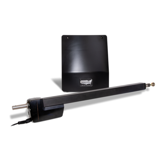
Part # 630041 Wiring Harness Optional Accessories & LCR Items: See accessories section for complete list and descriptions Ranger HD Actuator Part # 510006 4 Button Transmitter - Part # 030212 Ranger I - 1 per Push to Operate Button -... -
Page 9: General Tool Requirements
HARDWARE INVENTORY Support Bracket Bronze Bushing Part # 610425 Part # 610530 Ranger I - 1 per Ranger I - 2 per Ranger II - 2 per Ranger II - 4 per ⅜ Mounting Tube ” Bolt Part # 610102 Part # 610512 Ranger I - 1 per Ranger I - 1 per... -
Page 10: Actuator Dimensions / Control Box Dimensions
ACTUATOR DIMENSIONS Ranger HD 42.5” (Measurements are to center of hole.) 30.25” 3.25” TOP VIEW 3” Housing width 7.75” Rear housing to motor end 9” Pro 80 25.25” (Measurements are to center of hole.) 17.25” .75” TOP VIEW 3.2” Housing width 5.25”... -
Page 11: Gate Qualifications/Applications
14.5” BOX DIMENSIONS 17.7” 14.25” Mounting Holes 4 Places 11.7” GATE QUALIFICATIONS/APPLICATIONS The pictures below are provided as a guide to help understand the types of gates and size to provide many years of operation. Ornamental Iron Farm Gate PRO80 / HD 20 feet max length. PRO80 - 13 feet max length. -
Page 12: Proper Gate Design
Gate MUST be level Since the gate is a major component of the system, great care and concern must be given to the gate design. USAutomatic, LLC is not responsible for Post any damage to a gate on which the gate operator is MUST be installed. -
Page 13: Mounting Site Review
Mounting Site Review Review the following items prior to installation and predetermine the solution to any problems which may exist: 1. Does sufficient space exist for mounting and future servicing of the operator and control box? 2. Which direction will the gate swing? a. -
Page 14: Determine Opening Method (Pull To Open Or Push To Open)
Determine Opening Method (PRO80 or HD) (pull to open or push to open) Pull to Open Installation This installation method is the most common where the gate swings into the property and the operator pulls the gate open. EXTENDED (Gate Closed) RETRACTED (Gate Open) Push to Open Installation This installation method is commonly used where the drive slopes upward into the property and the... -
Page 15: Determine Horizontal Mounting Location
Determine Horizontal Mounting Location (PRO80 or HD) Now that the type of installation (pull to open or push to open) has been determined, the vertical height position of the support bracket and actuator mounting tube must be determined. Refer to these examples to determine the mounting location of the gate bracket on the gate, which is needed to determine the location of the actuator mounting tube. -
Page 16: Determine Best Method For Actuator Mounting Brackets - Pull To Open
Determine Best Method for Actuator Mounting Brackets - PULL TO OPEN (PRO80 or HD) Study the examples below and determine the best method for your gate. The examples below are for left hand installations. Reverse for right hand installations. Square Post Actuator support bracket mounted Actuator support bracket mounted horizontally on hinge post... -
Page 17: Determine Best Method For Actuator Mounting Brackets - Push To Open
Determine Best Method for Actuator Mounting Brackets - PUSH TO OPEN (PRO80 or HD) Study the examples below and determine the best method for your gate. The examples below are for left hand installations. Reverse for right hand installations. Square Post Actuator support bracket mounted horizontally on hinge post Round Post... -
Page 18: Determine Best Method For Actuator Mounting Brackets - Columns
Set hinge post Set hinge post in corner behind column center of hinge center of hinge Dim A Dim A Dim B Dim B Actuator Mounting Bracket Installation Dimensions Operator Dimension A Dimension B Ranger HD 13” 6” 5” Ranger Pro80 7½”... -
Page 19: Mount Support Bracket
Mount Support Bracket (PRO80 or HD) Now that you have determined the method and the vertical mounting location of the Actuator Support Bracket, mount the support bracket in alignment with predetermined horizontal frame member as per the following examples. Bracket must be level in all directions. DO NOT mount support bracket in a manner that obstructs gate movement... -
Page 20: Installing Actuator Mounting Tube - Pull To Open
Dim A for 90° - 95° opening. Center of Hinge Dim B Dim A PULL TO OPEN - Actuator Hinge Mounting Tube Installation Dimensions Ranger HD Ranger HD Ranger Pro80 Ranger Pro80 Gate opening in degrees Dimension A Dimension B... -
Page 21: Installing Actuator Mounting Tube - Push To Open
Dim B * Dimensions shown are for 90° - 95° opening. Dim B Dim A PUSH TO OPEN - Actuator Hinge Mounting Tube Installation Dimensions Ranger HD Ranger HD Ranger Pro80 Ranger Pro80 Gate opening in degrees Dimension A Dimension B... -
Page 22: Installing Linear Actuator To Actuator Mounting Bracket
Install Linear Actuator to Actuator Mounting Bracket The linear actuator should be mounted to the actuator mounting bracket using the provided hardware. Assemble as shown below. Tighten lock nut securely. Pro80 ⅜” Bolt Part # 610512 Bronze Bushing Part # 610530 ⅜”... -
Page 23: Install Gate Bracket To Linear Actuator
Install Gate Bracket to Linear Actuator Install gate bracket and manual release pin to linear actuator as shown. PRO80 Install Gate Bracket to Gate (PULL TO OPEN INSTALLATION ONLY) The linear actuator was shipped from the factory set to the fully retracted position. The steps below will determine where the gate bracket is to be installed on the gate. -
Page 24: Install Ranger Control Box And Linear Actuator Cable
Install Control Box and Linear Actuator Cable The control box should be securely mounted to an object or surface strong enough to support the weight of the box, battery and other components to be installed. The box can be screwed or bolted to a suitable mount. The most common mounts are to an adjoining fence panel or wall. -
Page 25: Splicing Linear Actuator Cable Cable And Dual Gate Cable
USAutomatic Part# 630010 can be custom ordered and purchased in any length. Never make underground splices as moisture in connections will definitely cause system malfunctions. -
Page 26: Installing Monitored Entrapment Protection Devices
Installing Monitored Entrapment Protection Devices When the installation requires more than 1 monitored contact edge or 2 monitored photo eyes, the Monitored Entrapment Device Expansion Modual must be installed. (USAutomatic Part# 500015) Monitored Photo Eye (Type B1) Installation for Entrapment Protection ONLY. (page 3) Connect wires per the table below: All wiring should be done with power disconnected from control board. -
Page 27: Constant Pressure Installation
Install Battery Controller Power Source (AC or Solar) The USAutomatic battery controller can be powered by an DC transformer supplied with AC Models OR a solar panel supplied with Solar models. The DC Transformer and the Solar Panel are equipped with a DC plug for easy connection to the battery controller. - Page 28 Solar panel may be moved up to 200 feet from the control box to achieve adequate sunlight. See power source cable extension chart Appendix A for proper wire size. For convenience use the USAutomatic 75’ Cable Kit Part #520016. See Region Map below to determine cycles that can be expected. These numbers are based on a basic system with the standard 10 watt solar panel.
-
Page 29: Connect Power Source To Battery Controller
Charge Device plugs in here Connect Power Source to Battery Controller (Transformer or Solar Panel Kit) The battery controller accepts inputs from either the DC transformer or the solar panel. The transformer and solar panel come with a DC plug for easy installation. -
Page 30: Operating Gate For The First Time
Operating Gate for the First time Identify your installation below and verify the correct SW1 and SW2 dipswitch settings. Verify linear actuator type HD or PRO80 and set SW2 switch 4 to the correct position. HD - SW2 switch 4 OFF - press down on left side PRO80 - SW2 switch 4 ON - press down on the right hand side ON - Down on right... -
Page 31: Limit Adjustments
Limit Adjustments The control board limit adjustments are simple and easy to use. Control board has 4 adjustment dials for adjusting the desired stop positions. The nudge procedure below can be used to easily adjust the extend limit ONLY. If adjustment is made and the extension tube is adjusted past the desired extend position you must reduce the extend limit adjustment so that the gate extends and stops short of the desired position. -
Page 32: Pwm Adaptive Soft Stop Speed Control Adjustment
PWM Adaptive Soft Start / Stop Speed Control Adjustment The control board is equipped with adaptive adjustable PWM soft start / stop speed control. The factory preset speed is set at a value of 4. Depending on the installation a different speed setting might be needed. -
Page 33: Sensitivity Adjustments And Entrapment Alarm
Sensitivity Adjustment and Entrapment Alarm and Auto Close Setting The control board has 2 sensitivity adjustment dials located on the left side of the control board. These adjustments control the amount of current the control board will allow the motor to draw from the battery to operate your gate. - Page 34 Verifying Monitored Photo Eye (Type B1) Entrapment device Operation Only: Operate the gate and verify entrapment protection devices are working properly. Use the table below to determine correct operation. Type B1 - Photo Eye 2 Entrapment - Type B1 - Photo Eye 2 Entrapment - N/C input J2 pin 4 - Open Direction N/C input J2 pin 8 - Closed Direction...
-
Page 35: Ranger Control Board Information
Ranger Control Board Information The Ranger control board is capable of operating two gates. If your installation is a single gate you can operate the gate on the Gate 1 or Gate 2 connector. Set control switch “ON” for the connector being used. - Page 36 J2 Terminal Description The accessory connector is a plug which can be removed from the control board for ease of wiring and troubleshooting purposes. Pull out to remove. J2 Terminal Terminal +12 vdc Output (Maximum current output 750 milliamps) Common Ground Push Button Input (normally open contacts) (Push button, radio control, keypad, etc.)
- Page 37 SW1 Function Dip Switches ON - Down on right OFF - Down on left Switch Setting Factory Settings are shown in bold type Automatic Close Timer Enable Timer to close is activated (Not recommended unless safety devices are installed) Timer to close is disabled Contact Edge Monitored Monitored contact edge is installed.
-
Page 38: Programming Transmitter, Receiver And Wireless Keypad
Programming Transmitter and Receiver Operating frequency 433.92 MHz. Receiver can store up to 42 unique transmitter dipswitch code settings. Transmitter Setup: (It is recommended that the dipswitch code be changed from the default factory setting) Battery Compartment 1. Open the battery compartment door and locate the dipswitches. Door 2. - Page 39 Programming Your Wireless Keypad 050520 or 050550 050500 (plastic) (metal) PUK code PUK code ___________ ___________ Terms to Understand Access Code – The 2 to 5-digit code used to open the gate (24 unique codes are possible). If access code is less than 5 digits it requires the # sign after code is entered. Example: “2 #.” If code is 5 digits the # sign is not required.
- Page 40 Create Communication with Receiver: *for P1 (relay 1) access code: Receiver 1. Carry keypad to receiver location for programming. P1 Button 2. Enter Access Code for P1 (relay 1) on the keypad and continue P2 Button to press the last key entered (red light blinks). 3.
- Page 41 Changing Keypad Security Code: This keypad has a virtual dipswitch used to create your Security Code. The virtual dipswitch contains nine 3-position switches. To ensure neighboring keypads do not interfere with each other, the virtual switches should be positioned in a random pattern, using the following procedure. Example of random positioning of the virtual dipswitches to create a Security Code is shown below.
-
Page 42: Emergency Manual Release
Emergency Manual Release Remove the manual release pin at the gate bracket and open the gate by hand. Secure the gate before attempting to pass through. PRO80 Manual Release Pin Secure in place with pull clip. Release pin is predrilled for this purpose. -
Page 43: Accessories
For Dual Gates, see Gate Delay Feature Section. Magnetic Gate Lock (Non-USAutomatic product) Not suitable for solar charged systems. Suitable for AC charged systems. To activate the magnetic lock delay circuit, turn SW1 switch 6 on. Connect the negative wire from the magnetic gate lock to negative post of the battery. - Page 44 4. Hold P1 button about 2 seconds. When gate moves, programming is complete. 2 Button LCR Transmitter Part Number 030210 Standard Transmitter for all USAutomatic operators Operating Frequency 433.92 MHz 4 Button LCR Transmitter Part Number 030212 Operating Frequency 433.92 MHz...
- Page 45 Charge Cable Extension Pigtails Part Number 630038 Provides easy splicing of charging device cable. Works with AC Transformer and Solar Panel. Monitored Entrapment Device Expansion Module Part Number 500015 The expansion module is designed to monitor for the connection and proper operation of multiple monitored external entrapment devices.
- Page 46 Troubleshooting Guide Introduction The Ranger control board is equipped with four unique features to assist in troubleshooting a gate system. 1. The first and most helpful is the series of LED indicating lights. These lights will help to identify problems with all control circuits. To use the indicators, press and hold the “LED Indicator” button on the control board.
- Page 47 Terms and Definitions LED -Light Emitting Diode - small red lights on control board below J2 Terminal plug. Control board - Located inside the control box in the upper right corner. Linear Actuator - Connected to gate and hinge post - contains the motor, gearbox, rotary potentiometer and extension tube.
- Page 48 * IMPORTANT FIRST First thing to verify is that no monitored entrapment devices are creating the problem. STEP 1. Press the Open/Close button on the control board. If gate does not operate proceed to step 2. 2. Press the Type D S4 push button and hold to operate the gate. 3.
- Page 49 2. Dual gate will not 1. Follow steps 1 through 7 above. operate. (Ranger II) 2. Disconnect the actuator connectors plugged into the control board Gate 1 and Gate 2 (X1 and X2). Then locate the SW1 dipswitches on the control board. Turn off switch 4 (down on left side) and turn Verify monitored on switch 3 (down on the right side).
- Page 50 Photo Eye N/C contact monitoring - 1. Verify that SW1 dip switch 10 is ON press down on the right hand side. 2. Verify that dip switch SW1 switch 7 or 8 (photo eye monitor) is ON press down on the right hand side. Turn ON the ones being used. 3.
- Page 51 5. Gate begins to open 1. Open the control box cover and locate the Ranger control board. Locate the sensitivity adjustment potentiometer located on the or close but stops control board. The white center is adjustable and needs to be turned and reverses after a in a clockwise direction to increase force.
-
Page 52: Troubleshooting
8. Transmitter will not 1. Open the control box and locate the Ranger control board. Locate the “LED Indicator” push button and the “Push Button Input” LED operate the gate. under J2 Terminal 3. Push and hold the “LED indicator” push button, (LCR radio equipment then press the transmitter button and observe the “Push Button only) - Page 53 10. Photo-eye being 1. The first thing to check is the accessory wiring. The accessory needs power (+12 vdc) wired to J2 terminal 5 on the Ranger control used for vehicular board. It also needs ground, which can be wired to the battery or protection will not to J2 terminal 2 or 7 on the Ranger control board.
- Page 54 The transformer should read about 20 vdc, if the transformer output is incorrect the transformer needs to be replaced with USAutomatic part # 520009. Solar Charged Systems ONLY 1. Remove the solar panel plug from the battery controller input and measure the DC voltage from the solar panel.
-
Page 55: Appendix
Appendix USAutomatic Battery Controller Battery controller is designed to charge 12 vdc batteries of various types using either solar panel or DC transformer part # 520009. It also capable of charging 24 vdc battery if using a 24-volt solar panel. The package includes Power source input adapter plug. -
Page 56: Photo Eye Vehicular Protection Only
Photo Eye - Vehicular Protection Only Part Number 550011 - battery or hardwired transmitter Part Number 550014 - hardwire only Wiring Photo Eye to control board (Control Board part #500021) #550011 Photo eyes are recommended for all systems. This provides protection against the gate closing on objects that may be in the gate path. - Page 57 Installing Photo Eye For Vehicular Protection Only - NOT MONITORED The photo eye must be wired as shown and the correct dipswitches must be turned on for the PEPM software to work correctly. Detailed instructions are below with illustration. NOTE: Monitored Entrapment UL325 photo eye installation instructions refer to page 24 step 12a. 1.
-
Page 58: Installing App Receiver
Installing the APP receiver to the Control Board The USAutomatic NEXXGATE receiver module connects to the J7 plug on the control board. Follow the instructions included with the NEXXGATE receiver for setup. For solar chrged systems a 20 watt panel... -
Page 59: Warranty
Ranger Swing Gate Operator LIMITED WARRANTY USAutomatic, LLC warrants this product to be free of defects in materials for a period of 3 YEARS following purchase USAUTOMATIC, LLC will repair or replace the product free of charge, including parts, shop labor, return to customer shipping and handling. - Page 60 © USAutomatic, LLC, 2019 rev. A All rights reserved. No part of this may be reproduced by any means without the expressed written consent of the publisher. PROUDLY MADE IN THE USA www.USAutomaticGateOpeners.com | (800) 878-7829 | Sales@USAutomaticGateOpeners.com...
Need help?
Do you have a question about the Ranger HD and is the answer not in the manual?
Questions and answers