
Related Manuals for USAutomatic PATRIOT Series


Summary of Contents for USAutomatic PATRIOT Series
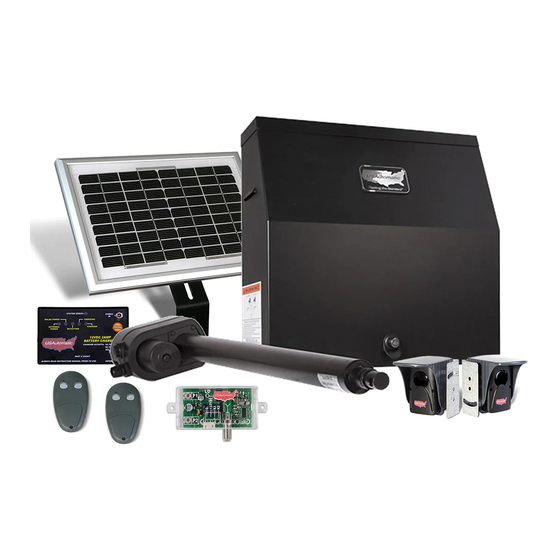
- Page 1 Installation/Owners Manual PATRIOT I Single Swing Gate Operator PATRIOT II Dual Swing Gate Operator Heavy Duty Battery Powered Solar or AC Charged...
- Page 2 Installation by a Qualified Technician is recommended to verify all safety concerns are addressed. © USAutomatic, LLC, 2019 rev. A All rights reserved. No part of this manual may be reproduced by any means without the expressed written consent of the publisher.
-
Page 3: Table Of Contents
TABLE OF CONTENTS INTRODUCTION Entrapment Device Requirements and Zones ....................2-3 Important Safety Instructions and Safety Installation Information .............4-5 Patriot Parts Inventory ..........................6 Patriot Hardware Inventory ..........................7 Actuator Dimensions .............................8 General Tool Requirements ...........................8 PREPARATION AND OVERVIEW Gate Qualifications/Applications ........................9 Proper Gate Design .............................10 INSTALLATION INSTRUCTIONS Mounting Site Review ......................... -
Page 4: Entrapment Device Requirements And Zones
Type B1 or Type B2 device that has been tested and approved with the gate operator. These devices are listed below. USAutomatic control boards can monitor one photo eye (B1) for the open direction, one photo eye (B1) for the closed direction and one contact edge (B2) for the open/close direction. If additional entrapment devices are required the USAutomatic expansion module (part # 500015) is required Type B1 - Non-contact sensor (photoelectric sensor or the equivalent). - Page 5 ENTRAPMENT ZONES The illustrations below are a guide to help identify entrapment areas for swing gate installations that must be protected. Other entrapment areas may exist and must be identified by the installer and protected by the appropriate entrapment protection device for the situation. Zone A - Leading edge of gate where it meets a 2nd gate, stop post or passes a column or post corner.
-
Page 6: Important Safety Instructions And Safety Installation Information
IMPORTANT SAFETY INSTRUCTIONS WARNING - TO REDUCE THE RISK OF INJURY OR DEATH 1. READ AND FOLLOW ALL INSTRUCTIONS 2. SAVE THESE INSTRUCTIONS!! 3. Always keep people and objects away from the gate. NO ONE SHOULD CROSS THE PATH OF A MOVING GATE. - Page 7 SAFETY INSTALLATION INFORMATION Install the gate operator when: • Operator is appropriate for the construction of the gate and usage class is correct for the installation. • All exposed pinch points are eliminated or guarded. • The gate is installed in a location where enough space is supplied between adjacent structures and the gate that when opening or closing the chance of entrapment is reduced.
-
Page 8: Patriot Parts Inventory
PARTS INVENTORY Operators purchased with LCR Radio All Operators include: Controls include: Cabinet with Control Board 2 Button Transmitter Part # 600020 Cabinet Part # 030210 Part # 602020 Cover Part # 500003 Control 2 per Board LCR Radio Receiver W/Harness Part # 030205 Patriot Actuator Part # 510001-SS... -
Page 9: Patriot Hardware Inventory
HARDWARE INVENTORY BRACKETS Support Bracket ⅜ ” SAE Flat Washers Part # 610425 Part #610516 Patriot I - 1 per Patriot I - 2 per Patriot II - 2 per Patriot II - 4 per Mounting Tube ⅜ inch Lock Nuts Part # 610102 Part # 610518 Patriot I - 1 per... -
Page 10: Actuator Dimensions
ACTUATOR DIMENSIONS 42.5” (Measurements are to center of hole.) 33.75” 3” 4.25” Housing width TOP VIEW Top of gear box to 9.5” wire harness. This includes wire harness clearance as harness exits bottom of housing. Rear Gear box to front 5.75”... -
Page 11: Preparation And Overview
PREPARATION AND OVERVIEW GATE QUALIFICATIONS The Patriot gate operator is designed for gates up to 20 feet in length and 650 pounds. The pictures below are provided as a guide to help understand the types of gates and size to provide many years of operation. -
Page 12: Proper Gate Design
Gate MUST be level Since the gate is a major component of the system, great care and concern must be given to the gate design. USAutomatic, LLC is not responsible for Post any damage to a gate on which the gate operator is MUST be installed. -
Page 13: Installation Instructions
INSTALLATION INSTRUCTIONS Mounting Site Review Review the following items prior to installation and predetermine the solution to any problems which may exist: 1. Does sufficient space exist for mounting and future servicing of the operator and control box? 2. Which direction will the gate swing? a. -
Page 14: Determine Opening Method (Pull To Open Or Push To Open)
Determine Opening Method (pull to open or push to open) Pull to Open Installation This installation method is the most common where the gate swings into the property and the operator pulls the gate open. EXTENDED (Gate Closed) RETRACTED (Gate Open) Push to Open Installation This installation method is commonly used where the drive slopes upward into the property and the operator pushes the gate open. -
Page 15: Determine Horizontal Mounting Location
Determine Horizontal Mounting Location Now that the type of installation (pull to open or push to open) has been determined, the vertical height position of the support bracket and actuator mounting tube must be determined. Refer to these examples to determine the mounting location of the gate bracket on the gate, which is needed to determine the location of the actuator mounting tube. -
Page 16: Determine Best Method For Actuator Mounting Brackets - Pull To Open
Determine Best Method for Actuator Mounting Brackets - PULL TO OPEN Study the examples below and determine the best method for your gate. The examples below are for left hand installations. Reverse for right hand installations. Square Post Actuator support bracket mounted Actuator support bracket mounted horizontally on hinge post horizontally on fence rail... -
Page 17: Determine Best Method For Actuator Mounting Brackets - Push To Open
Determine Best Method for Actuator Mounting Brackets - PUSH TO OPEN Study the examples below and determine the best method for your gate. The examples below are for left hand installations. Reverse for right hand installations. Square Post Actuator support bracket mounted horizontally on hinge post Round Post 3D Example... -
Page 18: Determine Best Method For Actuator Mounting Brackets - Columns
Determine Best Method for Actuator Mounting Brackets - COLUMNS Dimensions shown are for 90° - 95° opening. New Construction Existing Columns Set hinge post Set hinge post in corner behind column center of hinge center of hinge 13” 13” 6” 6”... -
Page 19: Mount Support Bracket
Mount Support Bracket Now that you have determined the method and the vertical mounting location of the Actuator Support Bracket, mount the support bracket in alignment with predetermined horizontal frame member as per the following examples. Bracket must be level in all directions. DO NOT mount support bracket in a manner that obstructs gate movement... -
Page 20: Installing Actuator Mounting Tube - Pull To Open
Install Actuator Mounting Tube - PULL TO OPEN Cut Actuator Mount Tube to proper length. Weld to support bracket. See table below for desired dimensions.) The actuator mounting tube will need to be cut so that the ⅜” hole location matches the dimensions for a pull to open system. -
Page 21: Installing Actuator Mounting Tube - Push To Open
Install Actuator Mounting Tube - PUSH TO OPEN Cut Actuator Mount Tube to proper length. Weld to support bracket. See table below for desired dimensions.) The actuator mounting tube will need to be cut so that the ⅜” hole location matches the dimensions for a push to open system. -
Page 22: Installing Linear Actuator To Actuator Mounting Bracket
Install Linear Actuator to Actuator Mounting Bracket The linear actuator should be mounted to the actuator mounting bracket using the provided hardware. Assemble as shown below. Tighten lock nut securely. Note: The linear actuator may be installed UPSIDE down to facilitate limit adjustments at this point. Then after all adjustments have been made, install linear actuator correctly with cable pointing toward the ground. -
Page 23: Install Gate Bracket To Gate
Install Gate Bracket to Gate (PULL TO OPEN INSTALLATION ONLY) The linear actuator was shipped from the factory set to the fully retracted position. The steps below will determine where the gate bracket is to be installed on the gate. 1. -
Page 24: Install Patriot Control Board
Install Patriot Control Box (cont.) When deciding where to mount the control box remember the actuator cable is 8 feet in length. If possible, mount the control box in a location that will allow the cable to be neatly routed. If it must be longer than the 8 feet, see Splicing Actuator Cable step. -
Page 25: Installing Receiver And Smart Charger / Charge Controller And Entrapment Siren
Installing Receiver, Charger / Charge Controller, and Entrapment Siren Before installing the charge controller into the control box connect the wiring harness to the charge controller as shown. Using the 2 nylon nuts provided install Charge Controller into control box in the upper left corner as shown. -
Page 26: 13A. Splicing Linear Actuator Cable Cable And Dual Gate Cable
USAutomatic Part# 630010 can be custom ordered and purchased in any length. Never make underground splices as moisture in connections will definitely cause system malfunctions. -
Page 27: Installing Monitored Entrapment Protection Devices
Installing Monitored Entrapment Protection Devices When the installation requires more than 1 monitored contact edge or 2 monitored photo eyes, the Monitored Entrapment Device Expansion Modual must be installed. (USAutomatic Part# 500015) Monitored Photo Eye (Type B1) Installation for Entrapment Protection ONLY. (page 3) Connect wires per the table below: All wiring should be done with power disconnected from control board. -
Page 28: Install Battery
Install Smart Charger / Charge Controller Power Source (AC or Solar) The Patriot gate operator’s battery is charged by the USAutomatic smart charger / charge controller. The USAutomatic smart charger / charge controller can be powered by an AC transformer supplied with Patriot AC Models OR a solar panel supplied with Patriot Solar models. - Page 29 The solar panel may be moved up to 500 feet from the control box to achieve adequate sunlight. See power source cable extension chart Appendix A for proper wire size. For convenience use the USAutomatic 75’ Cable Kit Part #520016 or USAutomatic Charge Cable Extension Pigtails part #630038.
-
Page 30: Connect Power Source To Smart Charger/Charge Controller
Charge Device plugs in here Connect Power Source to Smart Charger/ Charge Controller (Transformer or Solar Panel Kit) The charger / charge controller accepts inputs from either the AC transformer or the solar panel. The transformer and solar panel come with a DC plug for easy installation. Once the charge device is selected and installed connect the DC plug into the charge controller. -
Page 31: Operating Gate For The First Time
Operating Gate for the First time Before operating the gate for the first time please verify the following items: NOTE: This check must be performed before operating the gate for the first time. Failure to do so may damage the gate operator. Before operating the gate lets make sure the Patriot control board dipswitches are set correctly for your installation. -
Page 32: Optional Soft Stop For Retract And Extend Position
Optional Soft Stop for Retract and Extend Position The Patriot control board is equipped with a selectable soft stop feature if desired. Understanding how this feature operates is required before turning on control switch or possible control board damage may occur. The soft stop feature reduces the motor voltage for approximately the last 18”... -
Page 33: Making Retract And Extend Limit Adjustments
Making Retract and Extend Limit Adjustments The independent retract and extend limit adjustments are located on the bottom side of the linear actuator. These will need to be adjusted. Remove the dust plug to make adjustments. A flat blade screwdriver is included with the operator for adjustment purposes. Caution: Do not use a battery powered screw driver to make these adjustments or damage to the limit assembly may occur. -
Page 34: Sensitivity Adjustment And Entrapment Alarm
Sensitivity Adjustment and Entrapment Alarm and Auto Close Setting The Patriot control board has 2 sensitivity adjustment dials located in the upper left corner of the control board. These adjustments control the amount of current the control board will allow the motor to draw from the battery to operate your gate. -
Page 35: 26A. Verifying Monitored Entrapment Devices
Verifying Monitored Photo Eye (Type B1) Entrapment device Operation Only: Operate the gate and verify entrapment protection devices are working properly. Use the table below to determine correct operation. Type B1 - Photo Eye 2 Entrapment - Type B1 - Photo Eye 2 Entrapment - N/C input J2 pin 4 - Open Direction N/C input J2 pin 8 - Closed Direction... -
Page 36: Patriot Control Board Information
Patriot Control Board Information The Patriot control board is capable of operating two gates. If your installation is a single gate you can operate the gate on the Gate 1 or Gate 2 connector. Set control switch “ON” for the connector being used. - Page 37 J2 Terminal Description The accessory connector is a plug which can be removed from the control board for ease of wiring and troubleshooting purposes. J2 Terminal Place finger below connector and pull out to remove. Terminal +12 vdc Output (Maximum current output 1.5 amp - 1500 milliamps) Common Ground Input Push Button Input (normally open contacts)
- Page 38 DS1 Function Dip Switches ON - Down on right OFF - Down on left Switch Setting Factory Settings are shown in bold type Automatic Close Timer Enable Timer to close is activated (Not recommended unless safety devices are installed) Timer to close is disabled Timer to close activates only if open limit is Timer to Close Function activated...
- Page 39 DS2 Function Dip Switches DS2 Switches ON - Down on right OFF - Down on left Switch Setting Factory Settings are shown in bold type Solenoid Lock Enable / Solenoid lock output energizes half second Gate in Operation Indicator / before gate begins to move and releases 3 Gate Leaf Delay seconds after the gate begins to move.
-
Page 40: Programming Transmitter And Receiver
Programming Transmitter and Receiver Operating frequency 433.92 MHz. Receiver can store up to 42 unique transmitter dipswitch code settings. Transmitter Setup: (It is recommended that the dipswitch code be changed from the default factory setting) Battery Compartment 1. Open the battery compartment door and locate the dipswitches. Door 2. -
Page 41: Programming Wireless Keypad
Programming Your Wireless Keypad 050520 or 050550 050500 (plastic) (metal) PUK code PUK code ___________ ___________ Terms to Understand Access Code – The 2 to 5-digit code used to open the gate (24 unique codes are possible). If access code is less than 5 digits it requires the # sign after code is entered. Example: “2 #.” If code is 5 digits the # sign is not required. - Page 42 Create Communication with Receiver: *for P1 (relay 1) access code: Receiver 1. Carry keypad to receiver location for programming. P1 Button 2. Enter Access Code for P1 (relay 1) on the keypad and continue P2 Button to press the last key entered (red light blinks). 3.
- Page 43 Changing Keypad Security Code: This keypad has a virtual dipswitch used to create your Security Code. The virtual dipswitch contains nine 3-position switches. To ensure neighboring keypads do not interfere with each other, the virtual switches should be positioned in a random pattern, using the following procedure. Example of random positioning of the virtual dipswitches to create a Security Code is shown below.
-
Page 44: Periodic Service / Emergency Manual Release
PERIODIC SERVICE All gate operators require periodic checking and adjustments of the control mechanism for force (load), speed and sensitivity. These checks should be made by a qualified technician to verify proper adjustment and operation of all safety related components including those mentioned above. All accessories and monitored safety devices must be checked. -
Page 45: Accessories
For Dual Gates, see Gate Delay Feature Section, pg 30, step 23. Magnetic Gate Lock (Non-USAutomatic product) Not suitable for solar charged systems. Suitable for AC charged systems. To activate the magnetic lock delay circuit, turn DS2 switch 2 on. Connect the ground wire from the magnetic gate lock to J1 Common Gnd terminal. - Page 46 4. Hold P1 button about 2 seconds. When gate moves, programming is complete. 2 Button LCR Transmitter Part Number 030210 Standard Transmitter for all USAutomatic operators Operating Frequency 433.92 MHz 4 Button LCR Transmitter Part Number 030212 Operating Frequency 433.92 MHz...
- Page 47 12/24 Vdc Receiver AC/DC Part Number 030207 - Ideal for gate operators with 12 or 24 VDC/VAC supply power. Not recommended for solar applications. - Dual channel NO and NC contacts. - Two relays - Primary relay momentary, monitored relay has momentary or latching mode.
- Page 48 Troubleshooting Guide Introduction The Patriot control board is equipped with four unique features to assist in troubleshooting a gate system. 1. The first and most helpful is the series of LED indicating lights. These lights will help to identify problems with the actuator limit switches and all control circuits. To use the indicators, press and hold the “LED Indicator”...
- Page 49 Terms and Definitions LED - Light Emitting Diode - small red lights on control board. Control board - Located inside the control box in the upper right corner. Receiver - Located inside the control box on the left side - coax cable connected to it. Remote/Transmitter - Hand held unit with 2 buttons, used to operate the gate, sends signal to receiver when button is pressed.
- Page 50 Summary of Syptoms Included in This Guide 1. Single gate will not operate. 2. Dual gate will not operate. 3. My single or Dual gate will not operate. Monitored entrapment devices are installed. 4. My gate opens/closes slowly. 5. My Gate will not automatically close. 6.
- Page 51 * IMPORTANT FIRST First thing to verify is that no monitored entrapment devices are creating the problem. STEP 1. Press the Open/Close button on the control board. If gate does not operate proceed to step 2. 2. Press the S4 push button and hold to operate the gate. 3.
- Page 52 2. My dual gate will not 1. Follow steps 1 through 4 above. operate. (Patriot II) 2. Disconnect the actuator connectors plugged into the control board Gate 1 and Gate 2 (X1 and X2). Then locate the DS1 dipswitches on Verify monitored the control board.
- Page 53 Photo Eye N/C contact monitoring - closed direction 1. Verify that DS1 dip switch 10 is ON press down on the right hand side. 2. Verify that dip switch DS1 switch 8 (photo eye closed only N/C) is ON press down on the right hand side. 3.
- Page 54 Not likely on AC charged system. Verify that charger is working correctly and inspect charger and wires for damage. NOTE: The USAutomatic charger does not output any voltage or current when disconnected from the battery. You cannot check charger by disconnecting from battery and measuring voltage output.
- Page 55 5. My gate will not NOTE: If DS1 switch 1 is on and switch 2 is off then the gate should automatically close from any position. If switch 2 is also on automatically close the gate will only automatically close if the “Retract Limit” LED (both “open limit”...
- Page 56 6. Gate begins to open 1. Remove control box cover and locate the Patriot control board. Locate the sensitivity adjustment (see page 39) potentiometer or close but stops located on the control board. The white center is adjustable and and reverses after a needs to be turned in a clockwise direction to increase force.
- Page 57 8. Dual Gate opens 1. This is most likely caused by an incorrect limit switch adjustment. First determine which gate is in need of adjustment. or closes then immediately 2. Locate the DS1 switches on the Patriot control board. Switch 3 and reverses direction.
- Page 58 9a. Wiring harness 20 1. Possible short in the wiring harness. amp fuse blows when harness is connected to the battery 10. Transmitter will not 1. Open the control box and locate the Patriot control board. Locate the “LED Indicator” push button and the “Push Button Input” LED. Push operate the gate.
- Page 59 11. Photo-eye being 1. The first thing to check is the accessory wiring. The accessory needs power (+12 vdc) wired to battery positive terminal or to J2 pin 1 on used for vehicular the Patriot control board. It also needs ground, which can be wired protection will not to the battery or to J2 pin 2 or 7 on the Patriot control board.
-
Page 60: Troubleshooting
13. Gate opens using 1. The problem is most likely the programming of the LCR receiver (P2 relay is programmed to latch mode) transmitter, but will not close using 2. On the Patriot control board locate press and hold the “LED transmitter. - Page 61 15. Charger / Charge 1. This indicated that the battery is not connected to the charger / charge controller. controller “External Power or Solar 2. Verify that the 2 wire harness going to the battery is connected to the Power Light & battery and also connected to the charger / charge controller.
- Page 62 AC charged system where the charger has power connected to it continually. AC Charged Systems ONLY A. If your system is equipped with the USAutomatic charger / charge controller part # 520007 and is AC charged (not solar) verify the charger / charge controller is properly working. The “external Power”...
- Page 63 4. If the solar panel DC voltage checks good and the “solar power” light does not come ON when connected to the charger / charge controller then it is bad, replace with USAutomatic part # 520007. 18. Verifying Charge 1. Disconnect the black lead from the battery.
-
Page 64: Appendix
Appendix Photo Eye - Vehicular Protection Only Part Number 550011 - battery or hardwired transmitter Part Number 550014 - hardwire only Wiring Photo Eye to Patriot Control board (Control Board part #500003) #550011 Photo eyes are recommended for all systems. This provides protection against the gate closing on objects that may be in the gate path. - Page 65 Installing Photo Eye For Vehicular Protection Only - NOT MONITORED The photo eye must be wired as shown and the correct dipswitches must be turned on for the PEPM software to work correctly. Detailed instructions are below with illustration. NOTE: Monitored Entrapment UL325 photo eye installation instructions refer to page 25 step 14a. 1.
- Page 66 Extending Power Source Cable (AC or Solar) If charge device cable needs to be extended to reach the charge controller use “Patriot Charge Cable Extension Pigtails” Part Number 630038 (see figure). These DC plug pigtails connect to each end of a customer provided extension cable.
-
Page 67: Charge Controller
CHARGE CONTROLLER L.E.D. DESCRIPTIONS EXTERNAL POWER ADAPTOR - Illuminates continuously while power from A.C. Power Supply Adaptor is sensed. SOLAR PANEL - Illuminates continuously while power from Solar Panel is sensed. DETECTION - If illuminated for longer than 3 seconds check connection on battery. CHARGING - Continuous or flashing indicates charging –... -
Page 68: Extending Charge Device Location
POSSIBLE REMEDIES TO CHARGE CONTROLLER ‘FAILURES’ WRONG BATTERY VOLTAGE Charger connected to a 24v battery. Reconnect to a battery rated at 12Vdc. REVERSE BATTERY Check and correct any reverse battery. CONNECTION THERMAL RUNAWAY Old Battery - cells, inside battery, age differently. During CONDITION charging, and over the course of many years of operation, OR, many battery discharges to levels beyond 100%... - Page 69 Patriot Swing Gate Operator LIMITED WARRANTY USAutomatic, LLC warrants this product to be free of defects in materials for a period of 3 YEARS following purchase USAUTOMATIC, LLC will repair or replace the product free of charge, including parts, shop labor, return shipping and handling to customer.
- Page 72 © USAutomatic, LLC, 2019 rev. A All rights reserved. No part of this may be reproduced by any means without the expressed written consent of the publisher. PROUDLY MADE IN THE USA www.usautomatic.com...
Need help?
Do you have a question about the PATRIOT Series and is the answer not in the manual?
Questions and answers
I have the Patriot 500016 board on my gate opener. I recently installed an automatic gate lock. It usually works great, but occasionally the gate doesn't unlock so the opener overloads and won't open the gate. The gate is 10' wide and very light. Can you give me any advice? Will it help to engage the soft stop function?
To resolve the issue of the USAutomatic Patriot 500016 board not unlocking the gate consistently:
1. Check Sensitivity Setting: Locate the sensitivity adjustment potentiometer on the control board. Turn it clockwise to increase force. A setting of 5 usually works for most gates. If it requires above 8, inspect for mechanical problems like:
- Incorrect hinges
- Gate touching the ground
- Unlevel gate
- Bent actuator arm
2. Inspect Limit Switch Adjustment: If a single gate opens or closes incorrectly, check and adjust the limit switches located at the bottom of the control box.
3. Verify Accessory on J2 Connector: If the gate closes automatically when tested, the accessory connected to the J2 connector (with LED on) may be faulty and should be repaired.
4. Check Mounting and Connections: Ensure all actuator mounts are tight and secure. Loose mounts can cause improper operation. Do not use lag bolts.
5. Power Safety: Disconnect battery power before wiring or servicing to prevent damage.
Regarding the soft stop function:
- The soft stop feature reduces motor force in the last 18” of travel to prevent gate slap.
- It is useful for long, lightweight gates but does not affect unlocking consistency.
- It should only be enabled after understanding its setup procedure.
Conclusion: Engaging the soft stop function will not resolve unlocking issues. Focus on mechanical alignment, correct sensitivity, and electrical connections to fix inconsistent unlocking.
This answer is automatically generated
@Mr. Anderson Thanks! I'll get to work.
@Mr. Anderson I tightened everything up and re-aligned the lock and things seem to be working smoothly. Thanks again for your help!
Patriot 2 gate opener gate will not open or close, both extend and retract lights are on when tested, arm fully extended
If both the extend and retract limit LEDs are on and the USAutomatic Patriot 2 gate opener will not open or close, the issue is likely with misadjusted limit switches. Limit switches need to be adjusted so that only one LED is on at a time. Having both LEDs on can prevent operation and may cause a fuse to blow if the actuator tries to move further in an incorrect direction. Adjust the limit switches until only the correct LED is on based on the actuator’s position.
This answer is automatically generated
gate continues to run short spans open & close