Table of Contents
Advertisement
Quick Links
Advertisement
Chapters
Table of Contents

Related Manuals for AMD MB500


Summary of Contents for AMD MB500
- Page 1 MB500 AMD Geode LX Mini ITX Motherboard USER’S MANUAL Version 1.1...
- Page 2 PS/2 is a trademark of International Business Machines Corporation. Microsoft Windows is a registered trademark of Microsoft Corporation. Winbond is a registered trademark of Winbond Electronics Corporation. All other product names or trademarks are properties of their respective owners. MB500 User’s Manual...
-
Page 3: Table Of Contents
Table of Contents Introduction ............1 MB500 Product Features ............. 1 Checklist ................2 Specifications ..............3 Board Dimensions ............... 4 Installations ............5 Installing the Memory ............6 Setting the Jumpers ............. 7 Connectors on MB500 ............11 Watchdog Timer Configuration ........22 BIOS Setup ............ - Page 4 This page is intentionally left blank. MB500 User’s Manual...
-
Page 5: Introduction
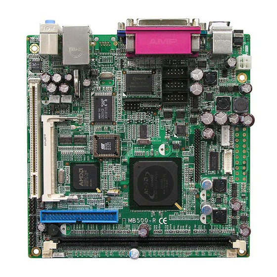
INTRODUCTION Introduction MB500 Product Features The MB500 Mini ITX motherboard incorporates the AMD Geode LX processor with speeds of 433MHz (LX700) or 500MHz (LX800). As of this writing, it comes with two board versions, namely: MB500 - AMD Geode LX700, 433MHz, Mini ITX motherboard w/... -
Page 6: Checklist
INTRODUCTION Checklist Your MB500 package should include the items listed below. • The MB500 Mini ITX board • This User’s Manual • 1 CD containing chipset drivers and flash memory utility • 1 x I/O Shield • Accompanying cables (IDE, COM, LPT) -
Page 7: Specifications
Audio Line in, Line out, Mic connectors on board Multi I/O AMD CS5536 + Winbond W83627HG + Fintek F81216D Supports 1x IDE, 1x FDD, 1x KB, 1x Mouse, 4x RS232, 1x LPT IDE Interface One enhanced IDE channel supports 2 IDE devices; supports... -
Page 8: Board Dimensions
INTRODUCTION Board Dimensions MB500 User’s Manual... -
Page 9: Installations
INSTALLATIONS Installations This section provides information on how to use the jumpers and connectors on the MB500 in order to set up a workable system. The topics covered are: Installing the Memory ..............6 Setting the Jumpers ..............7 Connectors on MB500 ............... 11 Watchdog Timer Configuration .......... -
Page 10: Installing The Memory
INSTALLATIONS Installing the Memory The MB500 embedded board supports one DDR memory sockets for a maximum total memory of 1GB in DDR memory type. The memory module capacities supported are 128MB, 256MB, 512MB and 1GB. Installing and Removing Memory Modules... -
Page 11: Setting The Jumpers
INSTALLATIONS Setting the Jumpers Jumpers are used on MB500 to select various settings and features according to your needs and applications. Contact your supplier if you have doubts about the best configuration for your needs. The following lists the connectors on MB500 and their respective functions. -
Page 12: Jumper Locations On Mb500
INSTALLATIONS Jumper Locations on MB500 Jumpers on MB500 ................Page JP2: Voltage Setting for LVDS ..............9 JP6: Clear CMOS Contents ................ 9 JP3, JP4, JP5: RS232/422/485 (COM2) Selection ........9 JP7: Case Open Setting ................10 JP8: CompactFlash Master/Slave Selection ..........10 JP9: ATX/AT Mode Select .............. -
Page 13: Jp2: Voltage Setting For Lvds
The following table describes the jumper settings for COM2 selection. COM2 RS-232 RS-422 RS-485 Function JP3: JP3: JP3: 3-5 & 4-6 1-3 & 2-4 1-3 & 2-4 Jumper Setting JP4: JP4: JP4: (pin closed) 3-5 & 4-6 1-3 & 2-4 1-3 & 2-4 JP5: JP5: JP5: MB500 User’s Manual... -
Page 14: Jp7: Case Open Setting
Jumper Setting Function Short/Closed Slave Open Master JP9: ATX/AT Mode Select Remarks: This jumper is supported only on board version 1.1 and above. Jumper Setting Function Pin 1-2 ATX Mode (default) Short/Closed Pin 2-3 AT Mode Short/Closed MB500 User’s Manual... -
Page 15: Connectors On Mb500
INSTALLATIONS Connectors on MB500 The connectors on MB500 allows you to connect external devices such as keyboard, floppy disk drives, hard disk drives, printers, etc. The following table lists the connectors on MB500 and their respective functions. Connector Locations on MB500 ..........12 CN1: DC Jack (DC in, 12V only) .......... -
Page 16: Connector Locations On Mb500
INSTALLATIONS Connector Locations on MB500 Connectors on MB500 MB500 User’s Manual... -
Page 17: Cn1: Dc Jack (Dc In, 12V Only)
Pin # Signal Name DCD, Data carrier detect DSR, Data set ready RXD, Receive data RTS, Request to send TXD, Transmit data CTS, Clear to send DTR, Data terminal ready RI, Ring indicator GND, ground Not Used MB500 User’s Manual... -
Page 18: Cn4: Parallel Port Connector
PD6, parallel data 6 Ground PD7, parallel data 7 Ground ACK, acknowledge Ground Busy Ground Paper empty Ground Select CN5: VGA CRT connector Signal Name Pin # Pin # Signal Name Green Blue N.C. N.C. N.C. N.C. HSYNC VSYNC MB500 User’s Manual... -
Page 19: Cn6: 10/100 Rj45 Connector (For Mb500F Only)
CN7: 10/100 RJ45 and USB Connectors CN7 is a stacked connector with RJ45 on top and 2 USB ports at the bottom. CN8: Line Out, Line In, Mic Connector CN9: Compact Flash Socket PCI1: PCI Slot DDR1: 184-pin DDR DIMM Socket MB500 User’s Manual... -
Page 20: J2: Atx Power Supply Connector
Power good 5VSB +12V The MB500 that you have received comes with a 2x4 connector that can be inserted into the J2 ATX power connector to be used with the PW94 accessory cable to serve as a power cable for a hard disk or CD-ROM. -
Page 21: J4: Lcd Inverter Connector
J4: LCD Inverter Connector Pin # Signal Name +12V Ground Backlight Enable J5: LCD (TTL) Connector Signal Name Pin # Pin # Signal Name SHFCLK VSYNC HSYNC Ground Ground Ground Ground Ground Ground LDEMOD Ground FP VDD EN BKL EN MB500 User’s Manual... -
Page 22: J6, J7, J8: Com2, Com3, Com4 Serial Ports
COM2 is jumper selectable for RS-232, RS-422 and RS-485. Pin # Signal Name RS-232 R2-422 RS-485 DATA- DATA+ Ground Ground Ground RTS- RTS+ CTS+ CTS- J9: IrDA Connector Pin # Signal Name No connect Ir RX Ground Ir TX MB500 User’s Manual... -
Page 23: J10: Digital 4-In 4-Out I/O Connector
J13 is a 3-pin header for the Wake On LAN function. Wake On LAN will function properly only with an ATX power supply with 5VSB that has 200mA. Pin # Signal Name +5VSB Ground Wakeup J14: For Left Speaker J15: USB Connector (USB2/USB3) Signal Name Signal Name Ground Ground MB500 User’s Manual... -
Page 24: J16: Front I/O Connector
CD Audio L FDD1: Floppy Drive Connector FDD1is a slim 26-pin connector and will support up to 2.88MB FDD. Signal Name Pin # Pin # Signal Name INDEX DRV_SEL DSK_CH MOTOR DINST STEP WDATA WGATE TRACK WPROT RDATA SIDE MB500 User’s Manual... -
Page 25: Ide1: Primary Ide Connector
Address 2 Chip select 0 Chip select 1 Activity Ground FAN1, FAN2: Fan Power Connectors This is a 3-pin header for fans. The fan must be a 12V (500mA) fan. Pin # Signal Name Ground +12V Rotation detection MB500 User’s Manual... -
Page 26: Watchdog Timer Configuration
;switch to LD8 mov cl, 0F5h call Read_Reg and al, NOT 08h call Write_Reg ;set count mode as second pop ax mov cl, 0F6h call Write_Reg ;set watchdog timer mov al, 01h mov cl, 30h call Write_Reg ;watchdog enabled MB500 User’s Manual... - Page 27 ; IN : None ; OUT : None ;[]=============================================== Unlock_Chip Proc Near mov dx, 4Eh mov al, 87h out dx, al out dx, al Unlock_Chip Endp ;[]================================================ ; Name : Lock_Chip ; IN : None ; OUT : None MB500 User’s Manual...
- Page 28 : Read_Reg ; IN : CL - register index ; OUT : AL - Value to read ;[]=================================================== Read_Reg Proc Near mov al, cl mov dx, 4Eh out dx, al inc dx al, dx Read_Reg Endp ;[]================================================ MB500 User’s Manual...
-
Page 29: Bios Setup
Power Management Setup ............37 PNP/PCI Configurations .............. 38 PC Health Status ................39 Load Fail-Safe Defaults ..............40 Load Optimized Defaults ............. 40 Set Password ................40 Save & Exit Setup ................ 40 Exit Without Saving ..............40 MB500 User’s Manual... -
Page 30: Bios Introduction
<PgUp> and <PgDn> keys to change entries, <F1> for help and <Esc> to quit. When you enter the Setup utility, the Main Menu screen will appear on the screen. The Main Menu allows you to select from various setup functions and exit choices. MB500 User’s Manual... - Page 31 These defaults have been carefully chosen by both Award and your system manufacturer to provide the absolute maximum performance and reliability. Changing the defaults could cause the system to become unstable and crash in some cases. MB500 User’s Manual...
-
Page 32: Standard Cmos Setup
Sun to Sat Month : 1 to 12 Date : 1 to 31 Year : 1999 to 2099 To set the date, highlight the “Date” field and use the PageUp/ PageDown or +/- keys to set the current time. MB500 User’s Manual... - Page 33 These fields identify the types of floppy disk drive A or drive B that has been installed in the computer. The available specifications are: 360KB 1.2MB 720KB 1.44MB 2.88MB 5.25 in. 5.25 in. 3.5 in. 3.5 in. 3.5 in. MB500 User’s Manual...
- Page 34 The system boot will not be halted for a disk error; it will stop for all other errors. All, But Disk/Key The system boot will not be halted for a key- board or disk error; it will stop for all others. MB500 User’s Manual...
-
Page 35: Advanced Bios Features
SCSI, CDROM, HDD-1, HDD-2, HDD-3, ZIP100, USB-FDD, LAN, USB-CDROM, USB-HDD and Disable. Boot Other Device These fields allow the system to search for an OS from other devices other than the ones selected in the First/Second/Third Boot Device. MB500 User’s Manual... - Page 36 Setup. When you select System, the system prompts for the User Password every time you boot up. When you select Setup, the system always boots up and prompts for the Supervisor Password only when the Setup utility is called up. MB500 User’s Manual...
- Page 37 OS/2 that depends on certain BIOS calls to access memory. The default setting is Non-OS/2. Small Logo (EPA) Show The EPA logo appears at the right side of the monitor screen when the system is boot up. MB500 User’s Manual...
-
Page 38: Advanced Chipset Features
This options for this field are Flat Panel, CRT and Panel & CRT. For flat panel, configuration settings include Flat Panel Type, Resolution (320x240 up to 1600x1200), Data Bus Type, Refresh Rate (60~100Hz), HSYNC Polarity, VSYNC Polarity, SHFCLK Active Period and LP Active Period. MB500 User’s Manual... -
Page 39: Integrated Peripherals
When Auto is selected, the BIOS will select the best available mode. IDE Primary/Secondary Master/Slave UDMA These fields allow your system to improve disk I/O throughput to 33Mb/sec with the Ultra DMA/33 feature. The options are Auto and Disabled. MB500 User’s Manual... - Page 40 Parallel Port Mode This field allows you to determine parallel port mode function. Standard Printer Port Enhanced Parallel Port Extended Capabilities Port 2nd SuperIO Device Onboard Serial Port 3 – 3E8h/IRQ11 Onboard Serial Port 4 – 2E8h/IRQ10 MB500 User’s Manual...
-
Page 41: Power Management Setup
When an I/O device wants to gain the attention of the operating system, it signals this by causing an IRQ to occur. When the operating system is ready to respond to the request, it interrupts itself and performs the service. MB500 User’s Manual... -
Page 42: Pnp Os Installed
This field allows you to set whether or not MPEG ISA/VESA VGA cards can work with PCI/VGA. When this field is enabled, a PCI/VGA can work with an MPEG ISA/VESA VGA card. When this field is disabled, a PCI/VGA cannot work with an MPEG ISA/VESA card. MB500 User’s Manual... -
Page 43: Pc Health Status
Temperatures/Voltages These fields are the parameters of the hardware monitoring function feature of the motherboard. The values are read-only values as monitored by the system and show the PC health status. MB500 User’s Manual... -
Page 44: Load Fail-Safe Defaults
Select this option to exit the Setup utility without saving the changes you have made in this session. Typing “Y” will quit the Setup utility without saving the modifications. Typing “N” will return you to Setup utility. MB500 User’s Manual... -
Page 45: Drivers Installation
If you find the items missing, please contact the vendor where you made the purchase. The contents of this section include the following: Entertainment Encryption/Decryption Controller Driver ..42 VGA Drivers Installation ............44 Audio Driver Installation ............47 MB500 User’s Manual... -
Page 46: Entertainment Encryption/Decryption Controller Driver
1. In the Windows operating system, go to the Device Manager. 2. As shown below, click the Entertainment Encryption/Decryption Controller under Other devices. 3. In the following window, click the Driver tab and click OK to continue. MB500 User’s Manual... - Page 47 Next to continue. Then select Install from a list of specific location (Advanced). Click Browse to find the driver’s path in the CD provided - \AMD\AES. Then, click Next to start the drivers installtion. Then click Finish after the wizard has finished installing the software for Geode LX AES Crypto Driver.
-
Page 48: Vga Drivers Installation
1. In the Windows operating system, go to the Device Manager. 2. As shown below, click the Video Controller (VGA Compatible under Other devices. 3. In the following window, click the Driver tab and click OK to continue. MB500 User’s Manual... - Page 49 DRIVERS INSTALLATION 4. In the Hardware Update Wizard, select No, not this time and click Next to continue. Then select Install from a list of specific location (Advanced). MB500 User’s Manual...
- Page 50 Check Include this location in the search. Click Browse to find the driver’s path in the CD provided or enter the path directly - \AMD\Vga\. Then, click Next to start the drivers installtion. Then click Finish after the wizard has finished installing the software for Advanced Micro Devices Win XP Graphics Driver.
-
Page 51: Audio Driver Installation
1. In the Windows operating system, go to the Device Manager. 2. As shown below, click the Multimedia Audio Controller under Other devices. 3. In the following window, click the Driver tab and click OK to continue. MB500 User’s Manual... - Page 52 DRIVERS INSTALLATION 4. In the Hardware Update Wizard, select No, not this time and click Next to continue. Then select Install from a list of specific location (Advanced). MB500 User’s Manual...
- Page 53 Check Include this location in the search. Click Browse to find the driver’s path in the CD provided or enter the path directly - \AMD\Audio\XPe. Then, click Next to start the drivers installtion. Then click Finish after the wizard has finished installing the software for GeodeLX Audio Driver (WDM).
- Page 54 DRIVERS INSTALLATION This page is intentionally left blank MB500 User’s Manual...
-
Page 55: Appendix
Parallel Port #1(LPT1) 360 - 36F Network Ports 3B0 - 3BF Monochrome & Printer adapter 3C0 - 3CF EGA adapter 3D0 - 3DF CGA adapter 3F0h - 3F7h Floppy Disk Controller 3F8h - 3FFh Serial Port #1(COM1) MB500 User’s Manual... -
Page 56: Interrupt Request Lines (Irq)
Serial Port #2 IRQ4 Serial Port #1 IRQ5 Reserved IRQ6 Floppy Disk Controller IRQ7 Parallel Port #1 IRQ8 Real Time Clock IRQ9 Reserved IRQ10 Reserved IRQ11 Reserved IRQ12 PS/2 Mouse IRQ13 80287 IRQ14 Primary IDE IRQ15 Secondary IDE MB500 User’s Manual...
Need help?
Do you have a question about the MB500 and is the answer not in the manual?
Questions and answers