Table of Contents
Advertisement
Quick Links
USER'S MANUAL
Of
MCP61P
Platform Processor Chipset
M/B For Socket AM2 64-bit Dual Core
AMD Processor
NO.G03-M26GT4V2-F
Rev: 1.0
Release date: June 2009
Trademark:
* Specifications and Information contained in this documentation are furnished for information use only, and are
subject to change at any time without notice, and should not be construed as a commitment by manufacturer.
Advertisement
Table of Contents

Related Manuals for AMD MCP61P Series


Summary of Contents for AMD MCP61P Series
- Page 1 USER'S MANUAL MCP61P Platform Processor Chipset M/B For Socket AM2 64-bit Dual Core AMD Processor NO.G03-M26GT4V2-F Rev: 1.0 Release date: June 2009 Trademark: * Specifications and Information contained in this documentation are furnished for information use only, and are subject to change at any time without notice, and should not be construed as a commitment by manufacturer.
-
Page 2: Table Of Contents
SPECIFICATION........................3 ITEM CHECKLIST ......................3 LAYOUT DIAGRAM & JUMPER SETTING …………………………………………..4 CHAPTER 2 HARDWARE INSTALLATION INSTALL SOCKET AM2 SUPPORTED AMD PROCESSOR ........5 INSTALL MEMORY......................5 EXPANSION CARDS ......................7 CHAPTER 3 CONNCTORS, HEADERS & JUMPERS SETTING CONNECTORS ........................7 HEADERS .......................... -
Page 3: Chapter 1 Introduction Of Mcp61P Motherboard Series
Technology up to 1000MHz. MCP61P Platform Processor Chipset motherboard series deliver the outstanding system performance and professional desktop platform solution with the advantages of new generation 64-bit AMD Socket AM2 Athlon64 & Sempron processors with an integrated low-latency high-bandwidth DDRII memory controller and a highly-scalable Hyper Transport technology-based system bus up to 1.0GHZ. -
Page 4: 1-1.1 Special Features Of Motherboard
Some special features---CPU Thermal Throttling/ CPU Vcore 7-shift this motherboard are designed for power user to use the over-clocking function in more flexible ways. But please be caution that the over-clocking maybe causes the fails in system reliabilities. This motherboard provides the guaranteed performance and meets the demands of the next generation computing. -
Page 5: Specification
CPU Socket AM2 Support 64bit AMD AM2 940-Pin package utilizes Flip-Chip Pin Grid Array package compatible processor Support for HTT 1GHz AMD Athlon 64 X2 processor Memory Socket 240-pin DDR2 Module socket x 2 Support 2 pcs DDR2 533 / DDR2 667 / DDR2 800 Modules... -
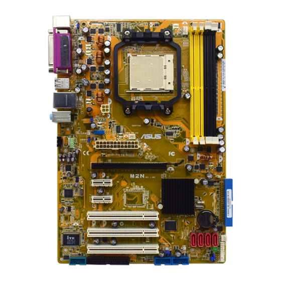
Page 6: Layout Diagram & Jumper Setting
Layout Diagram & Jumper Setting CPU Socket AM2 KBMS/USB Power On Jumper (JP1) CPU FAN PS2 KB/Mouse Port DDR2 Socket x 2 COM Connector ATX 12V Power Connector ATX Power Conn. VGA Connector USB Port RJ45 Over USB Connector Audio Connector Realtek RTL8102EL ATA 133 IDE... -
Page 7: Chapter 2 Hardware Installation
2-1 Install Socket AM2 Supported AMD Processor This motherboard provides a 940-pin surface mount, Zero Insertion Force (ZIF) socket, referred to as the mPGA940 socket supports AMD Athlon64 processor in the 940 Pin package utilizes Flip-Chip Pin Grid Array package technology. - Page 8 Recommend DIMM Module Combination One DIMM Module ----Plug in DIMM1 Plug in DIMM1 and DIMM2 for Dual channel function of 2-DIMM Design motherboard. For Dual channel Limited! 2 DIMM Modules plug in DIMM1 & DIMM2 of 2-DIMM Motherboard. DIMM1 & DIMM2 of 2-DIMM motherboard must be the same type, same size, and same frequency for dual channel function.
-
Page 9: Expansion Cards
Expansion Cards MCP61P motherboard series offer one 16-LANE PCI-Express x16 graphics slot of 4Gbyte/sec data transfer rate at each relative direction which get 3.5 times of bandwidth more than AGP8X and it’s up to a peak concurrent bandwidth of 8Gbyte/sec at full speed to guarantee the performance and compatibility of GPU graphics add-in cards. - Page 10 ** If you intend to use a PSU with 20-pin and 4-pin power plugs, make sure that the 20-pin power plug can provide at least 15A on +12V and the power supply unit has a minimum power rating of 350W. The system may become unstable or may not boot up if the power is inadequate.
- Page 11 (7) Floppy drive Connector (34-pin block): FDD1 This connector supports the provided floppy drive ribbon cable. After connecting the single plug end to motherboard, connect the two plugs at other end to the floppy drives. Pin 1 Floppy Drive Connector (8) Secondary IDE Connector (40-pin block): IDE1 This connector connects to the next set of Master and Slave hard disks.
-
Page 12: Headers
(9) Serial-ATA Port connector: SATA1 / SATA2/SATA3/SATA4 This connector supports the provided Serial ATA and Serial ATA2 IDE hard disk cable to connecting the motherboard and serial ATA hard disk. SATA1 SATA2 SATA3 SATA4 Serial-ATA1,2,3,4 Compatible Connectors (10) D-Sub 15-pin Connector: VGA VGA is the 15-pin D-Subminiature female connector;... - Page 13 (2) USB Port Headers (9-pin) : USB1/USB2 / USB3 These headers are used for connecting the additional USB port plug. By attaching an option USB cable, your can be provided with two additional USB plugs affixed to the back panel. USB1 USB3 USB2...
- Page 14 (8) FAN Power Headers: CHAFAN1, SYSFAN1, CPUFAN (4-pin) These connectors support cooling fans of 350mA (4.2 Watts) or less, depending on the fan manufacturer, the wire and plug may be different. The red wire should be positive, while the black should be ground. Connect the fan’s plug to the board taking into consideration the polarity of connector.
- Page 15 (11) SPDIF Out header: SPDIF Out The SPDIF output is capable of providing digital audio to external speakers or compressed AC3 data to an external Dolby digital decoder. Use this feature only when your stereo system has digital input function. SPDIF HDMI_SPDIF_OUT...
-
Page 16: Chapter 4 Useful Help
Chapter 4 USEFUL HELP 4-1 HOW TO UPDATE BIOS STEP 1. Prepare a bootable floppy disk. (You may make one by click START click RUN type SYS A: click OK) STEP 2. Download upgrade tools and the latest BIOS files of the motherboard from official website and then make a copy of it to your bootable floppy disk after decompressing these files STEP 3.
Need help?
Do you have a question about the MCP61P Series and is the answer not in the manual?
Questions and answers