Table of Contents
Advertisement
Quick Links
Advertisement
Chapters
Table of Contents

Related Manuals for AMD MD740


Summary of Contents for AMD MD740
- Page 1 MB740 AMD Geode NX Mini-ITX Motherboard USER’S MANUAL Version 1.0...
- Page 2 Award is a registered trademark of Award Software International, Inc. PS/2 is a trademark of International Business Machines Corporation. AMD is a trademark of Advanced Micro Devices, Inc. Microsoft Windows is a registered trademark of Microsoft Corporation. Winbond is a registered trademark of Winbond Electronics Corporation.
-
Page 3: Table Of Contents
Table of Contents Introduction ............1 Product Description ............. 1 Checklist ................2 MB740 Specifications ............3 Board Dimensions ............... 4 Installations ............5 Installing the CPU ............... 6 Installing the Memory ............7 Setting the Jumpers ............. 8 Connectors on MB740 ............11 BIOS Setup ............ - Page 4 THE MB740 MINI ITX MOTHERBOARD MB740 User’s Manual...
-
Page 5: Introduction
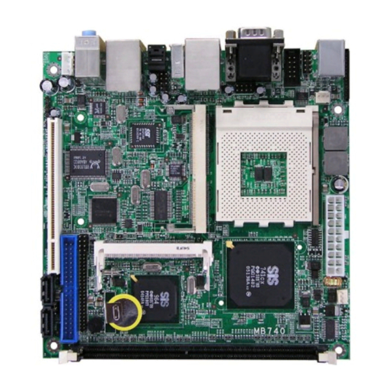
Product Description The MB740 Mini ITX board incorporates a Socket A processor socket that supports AMD Geode NX series processors that support processor speed up to 1.4GHz. With the SIS 741CX chipset, it delivers maximum performance for demanding thin client or embedded applications that require silent system operation. -
Page 6: Checklist
INTRODUCTION Checklist Your MB740 package should include the items listed below. • The MB740 AMD Geode Mini-ITX motherboard • This User’s Manual • 1 CD containing chipset drivers and flash memory utility • Cable kit (40-pin IDE, Serial port, Serial ATA) -
Page 7: Mb740 Specifications
2 x SATA, 6 x USB 2.0, 2 x COM, watchdog timer Digital I/O, optional 1394, 1x PCI, 1x Mini PCI System Socket A (462-pin) for AMD Geode, up to 1.4GHz (NX1250 = 667MHz, NX1500 = 1GHz, NX1750 =1.4GHz) System Memory DDR DIMM x 1, max. -
Page 8: Board Dimensions
INTRODUCTION Board Dimensions MB740 User’s Manual... -
Page 9: Installations
INSTALLATIONS Installations This section provides information on how to use the jumpers and connectors on the MB740 in order to set up a workable system. The topics covered are: Installing the CPU ................ 6 Installing the Memory ..............7 Setting the Jumpers ..............8 Connectors on MB740 ............... -
Page 10: Installing The Cpu
INSTALLATIONS Installing the CPU The MB740 board supports a Socket A processor socket for AMD NX Series processors. The Socket A processor socket comes with a lever to secure the processor. Raise this lever to about a 90° angle to allow the insertion of the processor. -
Page 11: Installing The Memory
INSTALLATIONS Installing the Memory The MB740 board supports one DDR memory socket for a maximum total memory of 1GB in DDR memory type. Installing and Removing Memory Modules To install the DDR modules, locate the memory slot on the board and perform the following steps: 1. -
Page 12: Setting The Jumpers
INSTALLATIONS Setting the Jumpers Jumpers are used on MB740 to select various settings and features according to your needs and applications. Contact your supplier if you have doubts about the best configuration for your needs. The following lists the connectors on MB740 and their respective functions. Jumper Locations on MB740 ............ - Page 13 INSTALLATIONS Jumper Locations on MB740 Jumpers on MB740 ................Page JP8: CompactFlash Slave/Master Selection ........10 JP9: 1394 EPROM Write Selection ............. 10 JP12: Clear CMOS Setting ..............10 JP14: RTL8110S-32 LAN Enable / Disable ........10 MB740 User’s Manual...
- Page 14 INSTALLATIONS JP8: CompactFlash Slave/Master Selection (option) Remarks: The CF socket and its corresponding slave/master Selection is optional. CF Setting Master Slave JP9: 1394 EPROM Write Selection 1394 EPROM For EPROM Write Normal JP12: Clear CMOS Setting JP12 Setting Normal Clear CMOS JP14: RTL8110S-32 LAN Enable / Disable JP14 Gigabit LAN...
-
Page 15: Connectors On Mb740
INSTALLATIONS Connectors on MB740 The connectors on MB740 allows you to connect external devices such as keyboard, floppy disk drives, hard disk drives, printers, etc. The following table lists the connectors on MB740 and their respective functions. Connector Locations on MB740 ..........12 KBMS1: PS/2 Keyboard and PS/2 Mouse Connectors .... -
Page 16: Connector Locations On Mb740
INSTALLATIONS Connector Locations on MB740 Remarks: GB LAN and 1394 are options found on MB740F only. MB740 User’s Manual... -
Page 17: Kbms1: Ps/2 Keyboard And Ps/2 Mouse Connectors
INSTALLATIONS KBMS1: PS/2 Keyboard and PS/2 Mouse Connectors PS/2 Mouse PS/2 Keyboard Signal Name Keyboard Mouse Signal Name Keyboard data Mouse data N.C. N.C. Keyboard clock Mouse clock N.C. N.C. CN3: COM1 and VGA Connector Signal Name Pin # Pin # Signal Name Not Used [[[[ Signal Name... -
Page 18: Cn4: 10/100 Rj-45 And Usb1/2 Ports
INSTALLATIONS CN4: 10/100 RJ-45 and USB1/2 Ports CN5: 1394 Connector J3: SPDIF Out Connector CN6: GbE RJ-45 and USB3/4 Ports CN7: Audio Connector The audio connector, from top to bottom, is composed of Line in, Line out and Microphone jacks. PWR1: ATX Power Supply Connector Signal Name Pin #... -
Page 19: Fan1: System Fan Power Connector
INSTALLATIONS FAN1: System Fan Power Connector FAN1 is a 3-pin header for system fans. The fan must be a 12V (500mA) fan. Pin # Signal Name Ground +12V Rotation detection FAN2: CPU Fan Power Connector FAN2 is a 3-pin header for the CPU fan. The fan must be a 12V fan. The CPU fan has a Smart Fan function that can be enabled with the BIOS. -
Page 20: Fdd1: Floppy Drive Connector
INSTALLATIONS Signal Name Pin # Pin # Signal Name Reset IDE Ground Host data 7 Host data 8 Host data 6 Host data 9 Host data 5 Host data 10 Host data 4 Host data 11 Host data 3 Host data 12 Host data 2 Host data 13 Host data 1... -
Page 21: Cn1: Digital I/O
INSTALLATIONS CN1: Digital I/O Signal Name Signal Name OUT3 OUT1 OUT2 OUT0 J1: USB5/6 Port Pin Header Signal Name Signal Name Ground Ground CN2: COM2 Serial Port COM2 Signal Name Pin # Pin # Signal Name DCD, Data carrier detect DSR, Data set ready RXD, Receive data RTS, Request to send... -
Page 22: J5: System Function Connector
INSTALLATIONS J5: System Function Connector Signal Name Signal Name Ground PS_ON Power LED Ground HDD Active Ground Reset ATX power on switch: Pins 1-2 Power LED: Pins 3-4 HDD LED: Pins 5-6 Reset switch: Pins 7-8 J6: Front Audio Connector Signal Name Signal Name Rear Audio R... -
Page 23: Cn9, Cn10: Serial Ata Connectors
INSTALLATIONS CN9, CN10: Serial ATA Connectors CN11: Compact Flash Connector J13: IrDA Connector Pin # Signal Name No connect Ir RX Ground Ir TX PCI1: PCI Slot (supports 2 Master) AGP1: MicroAGP Socket MB740 User’s Manual... - Page 24 INSTALLATIONS This page is intentionally left blank. MB740 User’s Manual...
-
Page 25: Bios Setup
BIOS SETUP BIOS Setup This chapter describes the different settings available in the Award BIOS that comes with the board. The topics covered in this chapter are as follows: BIOS Introduction ................ 22 BIOS Setup ................... 22 Standard CMOS Setup ..............24 Advanced BIOS Features ............. -
Page 26: Bios Introduction
BIOS Introduction The Award BIOS (Basic Input/Output System) installed in your computer system’s ROM supports Intel/AMD processors. The BIOS provides critical low-level support for a standard device such as disk drives, serial ports and parallel ports. It also adds virus and password protection as well as special support for detailed fine-tuning of the chipset controlling the entire system. - Page 27 BIOS SETUP Phoenix - AwardBIOS CMOS Setup Utility Standard CMOS Features Frequency/Voltage Control Advanced BIOS Features Load Fail-Safe Defaults Advanced Chipset Features Load Optimized Defaults Integrated Peripherals Set User Password Power Management Setup Save & Exit Setup PnP/PCI Configurations Exit Without Saving PC Health Status ESC : Quit : Select Item...
-
Page 28: Standard Cmos Setup
BIOS SETUP Standard CMOS Setup “Standard CMOS Setup” choice allows you to record some basic hardware configurations in your computer system and set the system clock and error handling. If the motherboard is already installed in a working system, you will not need to select this option. You will need to run the Standard CMOS option, however, if you change your system hardware configurations, the onboard battery fails, or the configuration stored in the CMOS memory was lost or damaged. - Page 29 BIOS SETUP To set the date, highlight the “Date” field and use the PageUp/ PageDown or +/- keys to set the current time. Time The time format is: Hour : 00 to 23 Minute : 00 to 59 Second : 00 to 59 To set the time, highlight the “Time”...
- Page 30 BIOS SETUP Video This field selects the type of video display card installed in your system. You can choose the following video display cards: EGA/VGA For EGA, VGA, SEGA, SVGA or PGA monitor adapters. (default) CGA 40 Power up in 40 column mode. CGA 80 Power up in 80 column mode.
-
Page 31: Advanced Bios Features
BIOS SETUP Advanced BIOS Features This section allows you to configure and improve your system and allows you to set up some system features according to your preference. Phoenix - AwardBIOS CMOS Setup Utility Advanced BIOS Features ITEM HELP Hard Disk Boot Priority Press Enter Virus Warning Disabled... - Page 32 BIOS SETUP Quick Power On Self Test When enabled, this field speeds up the Power On Self Test (POST) after the system is turned on. If it is set to Enabled, BIOS will skip some items. First/Second/Third Boot Device These fields determine the drive that the system searches first for an operating system.
- Page 33 BIOS SETUP Typematic Delay (Msec) When the typematic rate is enabled, this item allows you to set the time interval for displaying the first and second characters. By default, this item is set to 250msec. Security Option This field allows you to limit access to the System and Setup. The default value is Setup.
-
Page 34: Advanced Chipset Features
BIOS SETUP Advanced Chipset Features This Setup menu controls the configuration of the chipset. Phoenix - AwardBIOS CMOS Setup Utility Advanced Chipset Features DRAM Clock/Timing Control Press Enter ITEM HELP Advanced Host Control Press Enter Menu Level > AGP & P2P Bridge Control Press Enter OnChip AGP Control Press Enter... - Page 35 BIOS SETUP OnChip AGP Control The fields in this option and their respective default settings are as follows: Dual Display Support (Disabled) VGA Share Memory Size (32MB) Display Device Setting (Disabled); default is CRT1+LVDS for the Display Device when the setting is enabled. LCD Setting (Enabled);...
-
Page 36: Integrated Peripherals
BIOS SETUP Integrated Peripherals This section sets configurations for your hard disk and other integrated peripherals. The first screen shows three main items for user to select. Once an item selected, a submenu appears. Details follow. Phoenix - AwardBIOS CMOS Setup Utility Integrated Peripherals Press Enter ITEM HELP... - Page 37 BIOS SETUP Phoenix - AwardBIOS CMOS Setup Utility SIS OnChip PCI Device Enabled ITEM HELP Onboard FDC Controller 3F8/IRQ4 Menu Level > Onboard Serial Port 1 2F8/IRQ3 Onboard Serial Port 2 UART Mode Select Normal UR2 Duplex Mode Half IDE HDD Block Mode This field allows your hard disk controller to use the fast block mode to transfer data to and from your hard disk drive.
-
Page 38: Power Management Setup
BIOS SETUP Power Management Setup Phoenix - AwardBIOS CMOS Setup Utility Power Management Setup Enabled ITEM HELP ACPI Function S1(POS) ACPI Suspend User Define Menu Level > Power Management Disabled Suspend Type Susp, Stby ->Off Video Off Option Video Off In Suspend Break/Wake Switch Function Modem Use IRQ... - Page 39 BIOS SETUP Video Off Method This field defines the Video Off features. There are three options. V/H SYNC + Blank Default setting, blank the screen and turn off vertical and horizontal scanning. DPMS Allows BIOS to control the video display. Blank Screen Writes blanks to the video buffer.
-
Page 40: Pnp/Pci Configurations
BIOS SETUP PNP/PCI Configurations This option configures the PCI bus system. All PCI bus systems on the system use INT#, thus all installed PCI cards must be set to this value. Phoenix - AwardBIOS CMOS Setup Utility PnP/PCI Configurations Disabled Reset Configuration Data Menu Level Auto (ESCD) -
Page 41: Pc Health Status
BIOS SETUP PC Health Status This section shows the parameters in determining the PC Health Status. These parameters include temperatures, fan speeds and voltages. Phoenix - AwardBIOS CMOS Setup Utility PC Health Status ITEM HELP Shutdown Temperature Disabled Vcore(V) 1.02 V Menu Level >... -
Page 42: Auto Detect Pci Clk
BIOS SETUP Frequency/Voltage Control This section shows the user how to configure the processor frequency. Phoenix - AwardBIOS CMOS Setup Utility Frequency/Voltage Control Disabled ITEM HELP Auto Detect DIMM/PCI Clk Disabled Menu Level > Spread Spectrum Auto Detect PCI Clk This field enables or disables the auto detection of the PCI clock. -
Page 43: Load Fail-Safe Defaults
BIOS SETUP Load Fail-Safe Defaults This option allows you to load the troubleshooting default values permanently stored in the BIOS ROM. These default settings are non-optimal and disable all high-performance features. Load Optimized Defaults This option allows you to load the default values to your system configuration. - Page 44 BIOS SETUP This page is intentionally left blank. MB740 User’s Manual...
-
Page 45: Drivers Installation
DRIVERS INSTALLATION Drivers Installation This section describes the installation procedures for software and drivers under the Windows 2000 and Windows XP. The software and drivers are included with the motherboard. If you find the items missing, please contact the vendor where you made the purchase. The contents of this section include the following: SIS 741CX Chipset VGA Driver ........ -
Page 46: Sis 741Cx Chipset Vga Driver
DRIVER INSTALLATION SIS 741CX Chipset VGA Driver 1. Insert the CD that comes with the board. Click TI/ALi/SiS Chipset and then SiS741CX/SiS964 Chipset Drivers. MB740 User’s Manual... - Page 47 DRIVERS INSTALLATION 2. When the welcome screen to the InstallShield Wizard appears, click Next. 3. Click Next. (Select Typical setup, as default.). MB740 User’s Manual...
-
Page 48: Driver Installation
DRIVER INSTALLATION 4. Click Next, when asked to select the Program Folder listed. 5. Click Next for Setup to start the copying process. 6. When prompted, click Finish to restart the computer and for changes to take effect. MB740 User’s Manual... -
Page 49: Sis Chipset Ethernet Driver
DRIVERS INSTALLATION SIS Chipset Ethernet Driver 1. Insert the CD that comes with the board. Click TI/Ali/SiS Chipset and then SiS PCI Fast Ethernet Adapter Driver. 2. When the InstallShield Wizard appears, click Next to continue with the Ethernet drivers installation. 3. -
Page 50: Realtek Gigabit Ethernet Driver
DRIVER INSTALLATION Realtek Gigabit Ethernet Driver 1. Insert the CD that comes with the board. Click LAN Card on the left side and then Realtek Network Interface Controller Drivers to execute the REALTEK Gigabit and Fast Ethernet NIC Driver Setup. 2. -
Page 51: Realtek Ac97 Codec Driver
DRIVERS INSTALLATION Realtek AC97 Codec Driver 1. Insert the CD that comes with the board. Click TI/Ali/SiS Chipset and then Realtek AC’97 Codec Audio Driver. MB740 User’s Manual... - Page 52 DRIVER INSTALLATION 2. When the welcome screen to the InstallShield Wizard appears, click Next to proceed with the Realtek AC97 Audio Setup. 3. InstallShield Wizard is not complete and you are prompted to restart your computer. Restart the computer for changes to take effect. MB740 User’s Manual...
-
Page 53: Appendix
APPENDIX Appendix A. I/O Port Address Map Each peripheral device in the system is assigned a set of I/O port addresses which also becomes the identity of the device. The following table lists the I/O port addresses used. Address Device Description 000h - 01Fh DMA Controller #1 020h - 03Fh... -
Page 54: Interrupt Request Lines (Irq)
APPENDIX B. Interrupt Request Lines (IRQ) Peripheral devices use interrupt request lines to notify CPU for the service required. The following table shows the IRQ used by the devices on board. Level Function IRQ0 System Timer Output IRQ1 Keyboard IRQ2 Interrupt Cascade IRQ3 Serial Port #2... -
Page 55: C. Watchdog Timer Configuration
APPENDIX C. Watchdog Timer Configuration The WDT is used to generate a variety of output signals after a user programmable count. The WDT is suitable for use in the prevention of system lock-up, such as when software becomes trapped in a deadlock. Under these sorts of circumstances, the timer will count to zero and the selected outputs will be driven. -
Page 56: Watchdog Timer Configuration
APPENDIX printf("\n ITE8705 Watch Timer Tester (AUTO DETECT) \n"\ " Usage : ITE8705 reset_time\n"\ " Ex : ITE8705 3 => reset system after 3 second\n"\ " ITE8705 0 => disable watch dog timer\n"); //============================================================ void EnableWDT(int interval) Set_ITE8705_LD( 0x05); //Set Logic Device 5 Set_ITE8705_Reg( 0xFB, 0x88);... - Page 57 APPENDIX result = 1; goto Init_Finish; ITE8705_BASE = 0x00; result = 0; Init_Finish: return (result); //============================================================ void Unlock_ITE8705 (void) outportb(ITE8705_INDEX_PORT, ITE8705_UNLOCK1); outportb(ITE8705_INDEX_PORT, ITE8705_UNLOCK2); outportb(ITE8705_INDEX_PORT, ITE8705_UNLOCK3); if (ITE8705_BASE == 0x2E) outportb(ITE8705_INDEX_PORT, ITE8705_UNLOCK3); else outportb(ITE8705_INDEX_PORT, ITE8705_UNLOCK4); //============================================================ void Lock_ITE8705 (void) outportb(ITE8705_INDEX_PORT, ITE8705_LOCK); //============================================================ void Set_ITE8705_LD( unsigned char LD) Unlock_ITE8705();...
- Page 58 APPENDIX File name:ITE8705.H //============================================================ // THIS CODE AND INFORMATION IS PROVIDED "AS IS" WITHOUT // WARRANTY OF ANY // KIND, EITHER EXPRESSED OR IMPLIED, INCLUDING BUT NOT LIMITED // TO THE IMPLIED WARRANTIES OF MERCHANTABILITY AND/OR FITNESS FOR A // PARTICULAR PURPOSE. //============================================================ #ifndef __ITE8705_H #define __ITE8705_H...
-
Page 59: Digital I/O Sample Code
APPENDIX D. Digital I/O Sample Code File name: Main.CPP //--------------------------------------------------------------------------- // THIS CODE AND INFORMATION IS PROVIDED "AS IS" WITHOUT // WARRANTY OF ANY // KIND, EITHER EXPRESSED OR IMPLIED, INCLUDING BUT NOT LIMITED // TO THE // IMPLIED WARRANTIES OF MERCHANTABILITY AND/OR FITNESS FOR A // PARTICULAR // PURPOSE. - Page 60 APPENDIX unsigned char result; Set_ITE8705_LD(0x05); //switch to logic device 7 result = inportb(ITE8705_IO_PORT) & 0x0F; return (result); //--------------------------------------------------------------------------- void ClrKbBuf(void) while(kbhit()) getch(); //--------------------------------------------------------------------------- File name:ITE8705.CPP //============================================================ // THIS CODE AND INFORMATION IS PROVIDED "AS IS" WITHOUT // WARRANTY OF ANY // KIND, EITHER EXPRESSED OR IMPLIED, INCLUDING BUT NOT LIMITED // TO THE // IMPLIED WARRANTIES OF MERCHANTABILITY AND/OR FITNESS FOR A...
- Page 61 APPENDIX outportb(ITE8705_INDEX_PORT, ITE8705_UNLOCK2); outportb(ITE8705_INDEX_PORT, ITE8705_UNLOCK3); if (ITE8705_BASE == 0x2E) outportb(ITE8705_INDEX_PORT, ITE8705_UNLOCK3); else outportb(ITE8705_INDEX_PORT, ITE8705_UNLOCK4); //============================================================ void Lock_ITE8705 (void) outportb(ITE8705_INDEX_PORT, ITE8705_LOCK); //============================================================ void Set_ITE8705_LD( unsigned char LD) Unlock_ITE8705(); outportb(ITE8705_INDEX_PORT, ITE8705_REG_LD); outportb(ITE8705_DATA_PORT, LD); Lock_ITE8705(); //============================================================ void Set_ITE8705_Reg( unsigned char REG, unsigned char DATA) Unlock_ITE8705();...
- Page 62 APPENDIX #define ITE8705_UNLOCK3 0x55 #define ITE8705_UNLOCK4 0xAA #define ITE8705_LOCK 0xFF //============================================================ unsigned int Init_ITE8705(void); void Set_ITE8705_LD( unsigned char); void Set_ITE8705_Reg( unsigned char, unsigned char); unsigned char Get_ITE8705_Reg( unsigned char); //============================================================ #endif //__ITE8705_H MB740 User’s Manual...
Need help?
Do you have a question about the MD740 and is the answer not in the manual?
Questions and answers