
Related Manuals for AMD 7ZX-1


Summary of Contents for AMD 7ZX-1
- Page 1 7ZX-1 AMD Athlon /Duron Socket A Motherboard USER'S MANUAL AMD Athlon /Duron Socket A Processor Motherboard REV. 1.01 First Edition R-101-01-001211...
- Page 2 FCC Compliance Statement: This equipment has been tested and found to comply with limits for a Class B DECLARATION OF CONFORMITY Per FCC Part 2 Section 2. 1077(a) digital device, pursuant to Part 15 of the FCC rules. These limits are designed to provide reasonable protection against harmful interference in residential Responsible Party Name: G.B.T.
-
Page 3: Declaration Of Conformity
Declaration of Conformity We, Manufacturer/Importer (full address) G.B.T. Technology Träding GMbH Ausschlager Weg 41, 1F, 20537 Hamburg, Germany declare that the product ( description of the apparatus, system, installation to which it refers) Mother Board GA-7ZX is in conformity with (reference to the specification under which conformity is declared) in accordance with 89/336 EEC-EMC Directive EN 55011... -
Page 4: Table Of Contents
Table Of Content SUMMARY OF FEATURES..........................2 7ZX-1 MOTHERBOARD LAYOUT ........................3 CPU SPEED SETUP ............................. 4 CONNECTORS..............................5 & A ............................5 UDIO COM A / COM B / LPT P ..........................5 USB 1 C ............................5 ONNECTOR USB 2 C ............................ - Page 5 P/PCI C ..........................30 ONFIGURATIONS BIOS D ............................31 EFAULTS ............................. 32 ETUP EFAULTS ..........................33 NTEGRATED ERIPHERALS ............................36 ARDWARE ONITOR ........................37 UPERVISOR ASSWORD IDE HDD AUTO D ........................... 38 ETECTION & E ............................39 ETUP ............................. 40 ITHOUT AVING APPENDIX: ACRONYMS..........................
-
Page 6: Revision History
7ZX-1 Motherboard Revision History Revision Revision Note Date 1.01 Initial release of the 7ZX-1 motherboard Dec.2000 user’s manual. The author assumes no responsibility for any errors or omissions that may appear in this document nor does the author make a commitment to update the information contained herein. Third-party brands and names are the property of their respective owners. -
Page 7: Summary Of Features
7ZX-1 Motherboard Summary Of Features Form Factor 30.5 cm x 22.8 cm ATX size form factor, 4 layers PCB. AMD Athlon /Duron (K7) Socket A Processor 256K/64K L2 cache on die Supports 500MHz ~ 1GHz and faster Chipset Apollo KT133 ,consisting of:... -
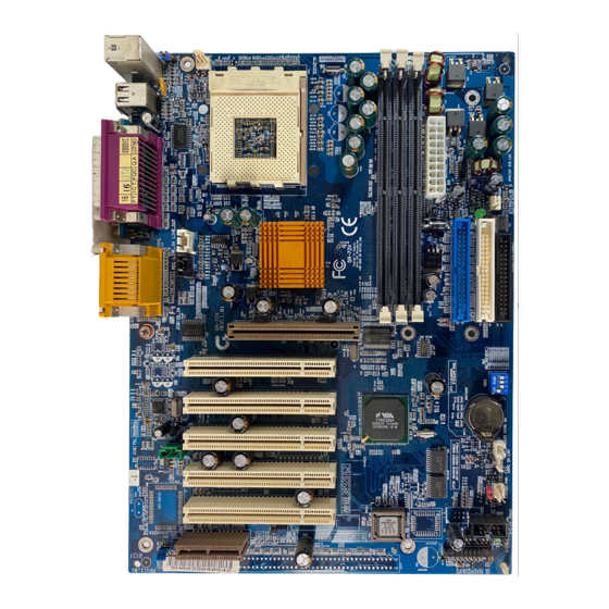
Page 8: 7Zx-1 Motherboard Layout
7ZX-1 Motherboard 7ZX-1 Motherboard Layout PS/2 Socket A CPU LED1 VT8363 7ZX-1 AGP 1 Clock PCI1 Generator PCI2 BAT1 VT82C 686A PCI3 PCI4 PCI5 BIOS USB2 JP16 JP17 JP18... -
Page 9: Cpu Speed Setup
W230H The FSB Speed of the VIA KT133 is 100MHz. AMD CPU Heat Sink Installation: Beware: Please check that the heat sink is in good contact with the CPU before you turn on your system. The poor contact will cause over heat, and might cause damage to your processor. -
Page 10: Connectors
Connectors Connectors Game & Audio Port Game Port Line Out 1 MIC In Line In COM A / COM B / LPT Port LPT Port COM A COM B USB 1 Connector Pin No. Definition USB V0 USB D0- USB D0+ USB V1 5 6 7 8 USB D1-... -
Page 11: Usb 2 Connector
Connectors USB 2 Connector Pin No. Definition USB D2- USB D2+ USB D3+ USB D3- PS/2 Keyboard & PS/2 Mouse Connector PS/2 PS/2 Mouse Mouse/Keyboard Pin No. Definition Data VCC(+5V) Clock PS/2 Keyboard J3: CPU Fan Pin No. Definition Control +12V SENSE... -
Page 12: Jp6: Power Fan
7ZX-1 Motherboard JP6: Power Fan Pin No. Definition Control +12V J2: Sysem Fan Pin No. Definition Control +12V SENSE ATX Power Pin No. Definition 3,5,7,13, 15-17 1,2,11 3.3V 4,6,19,20 +12V -12V Power Good 5V SB stand by+5V PS-ON(Soft On/Off) -
Page 13: Floppy Port
Connectors Floppy Port Red Line FDD1 IDE1(Primary), IDE2(Secondary) Port Red Line IDE 1 IDE 2 J15: AUX_IN Pin No. Definition AUX-L AUX-R... -
Page 14: J18: Cd Audio Line In
7ZX-1 Motherboard J18: CD Audio Line In Pin No. Definition CD-L CD-R J13: Ring Power On (Internal Modem Card Wake Up) Pin No. Definition Signal J12: Wake On LAN Pin No. Definition +5V SB Signal... -
Page 15: Jp8 / Led1: Str Led Connector & Dimm Led
Connectors JP8 / LED1: STR LED Connector & DIMM LED STR LED Connector External. DIMM LED J4: IR Pin No. Definition VCC (+5V) IR Data Input IR Data Output... -
Page 16: Panel And Jumper Definition
7ZX-1 Motherboard Panel And Jumper Definition J11: 2x11 Pins Jumper S P K P P P+ GN (Green Switch) Open: Normal Operation Not available at the case Close: Entering Green Mode GD (Green LED) Pin 1: LED anode(+) Pin 2: LED cathode( ) HD (IDE Hard Disk Active Pin 1: LED anode(+) LED) -
Page 17: Jp4: Rear Usb Device Wake Up Selection (Usb Connector Usb1)
Panel and Jumper Definition JP4: Rear USB Device Wake up Selection (USB Connector USB1) Pin No. Definition 1-2 Close Normal (Default) 2-3 Close USB Device Wake up (If you want to use "USB Dev Wakeup From S3-S5" function, you have to set the BIOS setting "USB Dev Wakeup From S3-S5"... -
Page 18: Jp11: Front Usb Device Wake Up Selection (Usb Port Usb2)
7ZX-1 Motherboard JP11: Front USB Device Wake up Selection (USB Port USB2) USB2 Pin No. Definition 1-2 close Normal (Default) Enabled Front USB Device 2-3 close Wake up (If you want to use "USB Dev Wakeup From S3-S5" function, you have to set the BIOS setting "USB Dev Wakeup From S3-S5"... -
Page 19: Bat1: Battery
Panel and Jumper Definition BAT1: Battery CAUTION Danger of explosion if battery is incorrectly replaced. Replace only with the same or equivalent type recommended by the manufacturer. Dispose of used batteries according to the manufacturer’s instructions. -
Page 20: Performance List
These data are just referred by users, and there is no responsibility for different testing data values gotten by users. (The different Hardware & Software configuration will result in different benchmark testing results.) AMD Thunderbird 950MHz, AMD Duron 700MHz DRAM... -
Page 21: Block Diagram
7ZX-1 Motherboard Block Diagram 100MHz Socket A 2X/4X System Bus 100MHz VT8363 3.3V SDRAM 100 / 133MHz 66MHz 100 / 133MHz 100 / 133MHz 66MHz 33MHz ICS 9248-141 33MHz or ICW W230H 5 PCI ATA66 IDE Channels 33MHz 14.318MHz 4 USB Ports 48MHz VT82C Game Port... -
Page 22: Suspend To Ram Installation
Suspend to RAM Installation Suspend To RAM Installation A.1 Introduce STR function: Suspend-to-RAM (STR) is a Windows 98 ACPI sleep mode function. When recovering from STR (S3) sleep mode, the system is able, in just a few seconds, to retrieve the last “state” of the system before it went to sleep and recover to that state. - Page 23 Suspend to RAM Installation B. Choose the “Stand by” item and press “OK” Define the system ”power on” button to initiate STR sleep mode: A. Double click “My Computer” and then “Control Panel” B. Double click the “ Power Management” item.
-
Page 24: A.4 How To Recover From The Str Sleep Mode
7ZX-1 Motherboard C. Select the “Advanced” tab and “Standby” mode in Power Buttons. D. Restart your computer to complete setup. Now when you want to enter STR sleep mode, just momentarily press the “Power on” button. A.4 How to recover from the STR sleep mode? There are five ways to “wake up”... -
Page 25: Memory Installation
7ZX-1 Motherboard Memory Installation The motherboard has 3 dual inline memory module (DIMM) sockets. The BIOS will automatically detects memory type and size. To install the memory module, just push it vertically into the DIMM Slot .The DIMM module can only fit in one direction due to the two notch. -
Page 26: Bios Setup
7ZX-1 Motherboard BIOS Setup BIOS Setup is an overview of the BIOS Setup Program. The program that allows users to modify the basic system configuration. This type of information is stored in battery-backed CMOS RAM so that it retains the Setup information when the power is turned off. -
Page 27: The Main Menu
BIOS Setup The Main Menu Once you enter AMI BIOS CMOS Setup Utility, the Main Menu (Figure 1) will appear on the screen. The Main Menu allows you to select from nine setup functions and two exit choices. Use arrow keys to select among the items and press <Enter>... -
Page 28: Standard Cmos Setup
7ZX-1 Motherboard User password Change, set, or disable password. It allows you to limit access to the system. IDE HDD auto detection Automatically configure hard disk parameters. Save & Exit Setup Save CMOS value settings to CMOS and exit setup. Exit Without Saving Abandon all CMOS value changes and exit setup. - Page 29 BIOS Setup form your hard disk vendor or the system manufacturer. CYLS. Number of cylinders HEADS number of heads PRECOMP write precomp LANDZONE Landing zone SECTORS number of sectors If a hard disk has not been installed select NONE and press <Enter>. Floppy Drive A / Drive B The category identifies the types of floppy disk drive A or drive B that has been installed in the computer.
-
Page 30: Bios Features Setup
7ZX-1 Motherboard BIOS Features Setup AMIBIOS SETUP – BIOS FEATURES SETUP ( C ) 1999 American Megatrends, Inc. All Rights Reserved 1st Boot Device Floppy 2nd Boot Device CDROM 3rd Boot Device IDE-0 S.M.A.R.T. for Hard Disks Disabled BootUp Num-Lock Floppy Drive Seek Enabled Password Check... -
Page 31: Chipset Features Setup
BIOS Setup Chipset Features Setup AMIBIOS SETUP – CHIPSET FEATURES SETUP ( C ) 1999 American Megatrends, Inc. All Rights Reserved *********DRAM Timing*** CAS# Drive 12 mA DRAM Frequency Auto RAS# Drive 24 mA SDRAM CAS# Latency Auto AGP Mode AGP Comp. - Page 32 7ZX-1 Motherboard USB Controller Enabled Enabled USB Controller. (Default Value) Disabled Disabled USB Controller. USB Legacy Support Keyboard/FD Set USB Legacy Support Keyboard / Floppy. KB/Mouse/F Set USB Legacy Support Keyboard / Mouse /Floppy. Disabled USB Legacy Support Function. (Default Disabled Value) BIOS Flash Protection...
-
Page 33: Power Management Setup
BIOS Setup Power Management Setup AMIBIOS SETUP – POWER MANAGEMENT SETUP ( C ) 1999 American Megatrends, Inc. All Rights Reserved ACPI Sleep Type S1/POS RTC Alarm Date Every Day USB Dev Wakeup From S3-S5 Disabled RTC Alarm Hour Suspend Time Out(Minute) Disabled RTC Alarm Minute Display Activity... - Page 34 7ZX-1 Motherboard System after AC Back Function Memory This function depends on computer status. . (Default Value) Soft-Off Set System Soft-Off Status Full-On Set System Full-On Status. Modem USE IRQ 3, 4, (Default Value) 5, 7, N/A Resume On Ring / LAN Disabled Disabled Resume On Ring / LAN.
-
Page 35: Pnp/Pci Configurations
BIOS Setup PnP/PCI Configurations AMIBIOS SETUP – PNP / PCI CONFIGURATION ( C ) 1999 American Megatrends, Inc. All Rights Reserved PnP Aware OS Reset Configuration Data VGA Boot from Disabled PCI AGP Palette Snoop DMA Channel 0 DMA Channel 1 DMA Channel 3 DMA Channel 5 DMA Channel 6... -
Page 36: Load Bios Defaults
7ZX-1 Motherboard Load BIOS Defaults AMIBIOS SIMPLE SETUP UTILITY-VERSION 1.23 ( C ) 1999 American Megatrends, Inc. All Rights Reserved STANDARD CMOS SETUP INTEGRATED PERIPHERALS BIOS FEATURES SETUP HARDWARE MONITOR SETUP CHIPSET FEATURES SETUP SUPERVISOR PASSWORD POWER MANAGEMENT SETUP USER PASSWORD PNP/PCI CONFIGURATION IDE HDD AUTO DETECTION Load BIOS Defaults (Y/N)? N... -
Page 37: Load Setup Defaults
BIOS Setup Load Setup Defaults AMIBIOS SIMPLE SETUP UTILITY-VERSION 1.23 ( C ) 1999 American Megatrends, Inc. All Rights Reserved STANDARD CMOS SETUP INTEGRATED PERIPHERALS BIOS FEATURES SETUP HARDWARE MONITOR SETUP CHIPSET FEATURES SETUP SUPERVISOR PASSWORD POWER MANAGEMENT SETUP USER PASSWORD Load SETUP Defaults (Y/N)? N PNP/PCI CONFIGURATION IDE HDD AUTO DETECTION... -
Page 38: Integrated Peripherals
7ZX-1 Motherboard Integrated Peripherals AMIBIOS SETUP – INTEGRATED PERIPHERALS ( C ) 1999 American Megatrends, Inc. All Rights Reserved OnBoard Serial Port A Auto OnBoard Serial Port B Auto Normal Serial PortB Mode Duplex Mode Auto OnBoard Parallel Port Parallel Port Mode Parallel Port DMA Auto Parallel Port IRQ... - Page 39 BIOS Setup Parallel Port Mode Using Parallel port as Enhanced Parallel Port. Using Parallel port as Extended Capabilities Port. (Default Value) Normal Normal Operation. EPP+EC Using Parallel port as Enhanced Parallel Port & Extended Capabilities Port. Parallel Port DMA Auto Set Auto to parallel port mode DMA Channel.
- Page 40 7ZX-1 Motherboard MPU-401 Enabled Enabled MPU-401. Disabled Disabled MPU-401. (Default Value) Ps. When Force Feedback joystick is used, MPU-401 needs to be Enable. MPU-401 I/O Address 330h- Set MPU-401 I/O Address to 330h-333h. (Default Value) 333h 300h- Set MPU-401 I/O Address to 300h-303h. 303h 310h- Set MPU-401 I/O Address to 310h-313h.
-
Page 41: Hardware Monitor
BIOS Setup Hardware Monitor AMIBIOS SETUP – HARDWARE MONITOR SETUP ( C ) 1999 American Megatrends, Inc. All Rights Reserved ACPI Shut Down Temp. Disabled CPU Temperature 32 C/89 F System Temperature 32 C/89 F CPU Fan Speed 7123 RPM System Fan Speed 0 RPM Vcore... -
Page 42: Set Supervisor / User Password
7ZX-1 Motherboard Set Supervisor / User Password When you select this function, the following message will appear at the center of the screen to assist you in creating a password. AMIBIOS SIMPLE SETUP UTILITY-VERSION 1.23 ( C ) 1999 American Megatrends, Inc. All Rights Reserved STANDARD CMOS SETUP INTEGRATED PERIPHERALS BIOS FEATURES SETUP... -
Page 43: Ide Hdd Auto Detection
BIOS Setup IDE HDD AUTO Detection AMIBIOS SETUP – STANDARD CMOS SETUP ( C ) 1999 American Megatrends, Inc. All Rights Reserved Date (mm/dd/yyyy) : Tue Jan 25, 2000 Time (hh/mm/ss) : 10:36:24 TYPE SIZE CYLS HEAD PRECOMP LANDZ SECTOR MODE Pri Master : Not Installed Pri Slave : Not Installed Sec Master : Not Installed... -
Page 44: Save & Exit Setup
7ZX-1 Motherboard Save & Exit Setup AMIBIOS SIMPLE SETUP UTILITY-VERSION 1.23 ( C ) 1999 American Megatrends, Inc. All Rights Reserved STANDARD CMOS SETUP INTEGRATED PERIPHERALS BIOS FEATURES SETUP HARDWARE MONITOR SETUP CHIPSET FEATURES SETUP SUPERVISOR PASSWORD POWER MANAGEMENT SETUP USER PASSWORD PNP/PCI CONFIGURATION IDE HDD AUTO DETECTION... -
Page 45: Exit Without Saving
BIOS Setup Exit Without Saving AMIBIOS SIMPLE SETUP UTILITY-VERSION 1.23 ( C ) 1999 American Megatrends, Inc. All Rights Reserved STANDARD CMOS SETUP INTEGRATED PERIPHERALS BIOS FEATURES SETUP HARDWARE MONITOR SETUP CHIPSET FEATURES SETUP SUPERVISOR PASSWORD POWER MANAGEMENT SETUP USER PASSWORD PNP/PCI CONFIGURATION IDE HDD AUTO DETECTION Quit without saving (Y/N) ? N... -
Page 46: Appendix: Acronyms
Appendix Appendix: Acronyms Acronyms Meaning ACPI Advanced Configuration and Power Interface POST Power-On Self Test Local Area Network Extended Capabilities Port Advanced Power Management Direct Memory Access Megahertz ESCD Extended System Configuration Data Central Processing Unit Symmetric Multi-Processing Universal Serial Bus Operating System Error Checking and Correcting Integrated Dual Channel Enhanced...
Need help?
Do you have a question about the 7ZX-1 and is the answer not in the manual?
Questions and answers