
Subscribe to Our Youtube Channel
Related Manuals for Portwell ROBO-8773VG


Summary of Contents for Portwell ROBO-8773VG
- Page 1 ROBO-8773VG Single Board Computer User's Manual P/N: B8981480 Version 1.0 Copyright © Portwell, Inc., 2007. All rights reserved. All other brand names are registered trademarks of their respective owners.
-
Page 2: Table Of Contents
3.6 SMBus ............................3-8 3.7 On-Board USB 2.0 Controller..................... 3-9 3.8 GPIO .............................. 3-9 3.8.1 Pin assignment........................3-9 3.8.2 ROBO-8773VG GPIO Programming Guide..............3-10 3.8.3 Example ..........................3-11 Chapter 4 BIOS Setup Information....................4-1 4.1 Entering Setup..........................4-1 4.2 Main Menu ........................... 4-2 4.3 Standard CMOS Setup Menu .................... -
Page 3: How To Use This Manual
Preface How to Use This Manual The manual describes how to configure your ROBO-8773VG system to meet various operating requirements. It is divided into five chapters, with each chapter addressing a basic concept and operation of Single Board Computer. Chapter 1 : System Overview. Presents what you have in the box and give you an overview of the product specifications and basic system architecture for this series model of single board computer. -
Page 4: Chapter 1 System Overview
ROBO-8773VG and it is just one example of several levels of products Portwell can supply to help our customers enhance their solutions portfolio, whether they are entry-level, value or performance. -
Page 5: Check List
System Overview Check List The ROBO-8773VG package should cover the following basic items: One ROBO-8773VG single board computer One dual Serial ports cable kit One Parallel port cable kit (2.0mm pitch) One FDC cable (2.0mm pitch) One IDE cable One Y-cable cable for PS/2 keyboard and mouse... - Page 6 Support three 3-pin headers for CPU, System and Power fans System Monitoring Feature Monitor CPU temperature, system temperature and major power sources, etc Bracket Support one Ethernet port with 2 indicators, dual USB ports, one Mini-DIN port for PS/2 keyboard/mouse, and one CRT port ROBO-8773VG User’s Manual...
-
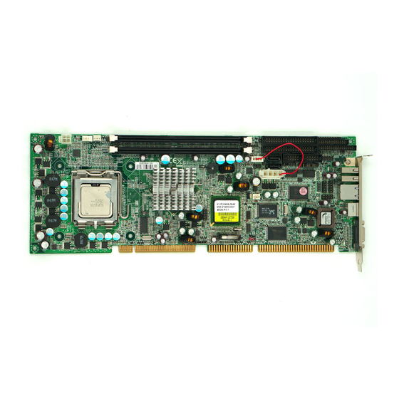
Page 7: Mechanical Drawing
‧Test Programs: Run Burning Test V4.0 ‧Connected Fans: Only CPU fan connected ‧Run Time: 10 minutes Operating Temperature: 0°C ~ 55°C (32°F ~ 131°F) Storage Temperature: -20°C ~ 80°C Relative Humidity: 0% ~ 95%, non-condensing 1.3.1 Mechanical Drawing ROBO-8773VG User’s Manual... -
Page 8: System Architecture
System Overview System Architecture The system architecture of ROBO-8773VG includes two main Intel chips - Intel ® 865G chipset supports Pentium 4 and Celeron D processor, DDR-SDRAM, 2D/3D graphic display, and 82801EA ICH5 that supports PCI bus interface, APM, ACPI compliant power management, USB port, SMBus communication, and Ultra DMA/33/66/100 IDE Master. - Page 9 USB Port 5,6 ISA ADDR/DATA USB Port 7,8 LPC to ISA ISA CTRL AC'97 LINK Winbond AC97 CON. W83627THF LPC SIO SATA Interface SATA X2 KEYBOARD FLOPPY PARALLEL SERIAL 1/2 F/W HUB MOUSE ROBO-8773VG System Block Diagram ROBO-8773VG User’s Manual...
-
Page 10: Chapter 2 Hardware Configuration
Hardware Configuration This chapter gives the definitions and shows the positions of jumpers, headers and connector. All of the configuration jumpers on ROBO-8773VG series are in the proper position. The default settings shipped from factory are marked with a star ( ). -
Page 11: Connector Allocation
IrDA Connector Secondary SATA Connector Primary USB Connector Standalone Power Connector Secondary USB Connector J29/J28/J32 External USB Connector Primary Ethernet RJ-45 Connector System FAN (3-pin Smart FAN) PS/2 Keyboard/Mouse Connector AC97 Connector On-board VGA CRT Connector SMBus Connector ROBO-8773VG User’s Manual... - Page 12 +5V (470 ohm pull-up for HDD LED+) HDD Active # (HDD LED-) J4: LAN Active/Link LED PIN No. Signal Description LAN1 Active ( LED+) LAN1 Link ( LED-) J6: Reset Button Connector PIN No. Signal Description Reset Signal Input (Active low) Ground ROBO-8773VG User’s Manual...
- Page 13 Signal Description RESET# Ground Data 7 Data 8 Data 6 Data 9 Data 5 Data 10 Data 4 Data 11 Data 3 Data 12 Data 2 Data 13 Data 1 Data 14 Data 0 Data 15 Ground ROBO-8773VG User’s Manual...
- Page 14 Ground Printer Select J12: External Wake On Ring Connector PIN No. Signal Description Ring Signal Input (Active low) Ground J13: External Wake On LAN Connector PIN No. Signal Description 5VSB Ground External WOL Signal Input (Active low) ROBO-8773VG User’s Manual...
- Page 15 Signal Description Pull-high 1K Ohm to +5VSB Power Button Signal Input (Active high) J17: ATX Power Control Connector PIN No. Signal Description ATX Power Good Signal (PW-OK) ATX 5V Stand-by (5VSB) ATX Power On Control (PS-ON) Ground ROBO-8773VG User’s Manual...
- Page 16 J20: COM2 Serial Port 2 Connector PIN No. Signal Description RS-232 DCD (Data Carrier Detect) RXD (Receive Data) TXD (Transmit Data) DTR (Data Terminal Ready) GND (Ground) DSR (Data Set Ready) RTS (Request to Send) CTS (Clear to Send) RI (Ring Indicator) ROBO-8773VG User’s Manual...
- Page 17 GPIO1 GPIO5 GPIO2 GPIO6 GPIO3 GPIO7 Ground Note: All General Purpose I/O ports can only apply to standard TTL ± 5% signal level (0V/5V), and each Fan. J23: IrDA Connector PIN No. Signal Description IRRX Ground IRTX ROBO-8773VG User’s Manual...
- Page 18 5V Dual is always available. It's supplied by either 5V VCC power source in normal operation mode or 5V standby power source in standby mode J30 : Primary Ethernet RJ-45 Connector PIN No. Signal Description MDI0+ (MDI0P) MDI0- (MDI0N) MDI1+ (MDI1P) MDI2+ (MDI2P) MDI2- (MDI2N) MDI1- (MDI1N) MDI3+ (MDI3P) MDI3- (MDI3N) ROBO-8773VG User’s Manual...
- Page 19 PIN No. Signal Description PIN No. Signal Description CLK_AC97 12V VCC ACZ_BIT_CLK ACZ_SDOUT ACZ_SDIN ACZ_SYNC ACZ_RST# J35: On-board VGA CRT Connector PIN No. Signal Description Green Blue Monitor ID0 (MONID0) (5V I/F) Ground Ground Ground Ground Ground ROBO-8773VG User’s Manual 2-10...
- Page 20 Monitor ID1 (MONID1) (5V I/F) VGA DDC Data (5V I/F) Horizontal Sync. (HSYNC) (5V I/F) Vertical Sync. (VSYNC) (5V I/F) VGA DDC Clock (5V I/F) J36: SMBus Connector PIN No. Signal Description SMBus Clock Ground SMBus Data ROBO-8773VG User’s Manual 2-11...
-
Page 21: Chapter 3 System Installation
(pin 1) of the CPU corresponds to the socket’s bevel end. Then press the CPU gently until it fits into place. If this operation is not easy or smooth, don’t do it forcibly. You need to check and rebuild the CPU pin uniformly. ROBO-8773VG User’s Manual... - Page 22 System Installation Triangle mark is meaning first pin position; kindly assemble and take aim at notch of top and bottom between CPU and socket. Figure 3-2 Figure 3-3 Figure 3-4 ROBO-8773VG User’s Manual...
-
Page 23: Main Memory
4) Follow the steps of installing a CPU to change to another one or place handling bar to close the opened socket. Configuring System Bus ROBO-8773VG will automatically detect the CPU used. CPU speed of Intel P4 can be detected automatically. Main Memory ROBO-8773VG provides two DDR-SDRAM DIMM sockets to support 333/400 DDR- SDRAM as main memory, Non-ECC, non-buffered DIMMS only. -
Page 24: Installing The Single Board Computer
Step 1 : Check all jumpers setting on proper position Step 2 : Install and configure CPU and memory module on right position Step 3 : Place ROBO-8773VG into the dedicated position in the system Step 4 : Attach cables to existing peripheral devices and secure it WARNING Please ensure that SBC is properly inserted and fixed by mechanism. -
Page 25: Chipset Component Driver
3.3.1 Chipset Component Driver The chipset used on ROBO-8773VG is relatively new which operating systems might not be able to recognize. To overcome this compatibility issue, for Windows Operating Systems such as Windows-2000/XP, please install its INF before any of other Drivers are installed. -
Page 26: On-Board Ac-97 Audio Device
This onboard Audio function is supported by Winbond W83627THG embedded AC’97 Codec Controller. Driver Support Please find Sound driver in \Audio\Ac97 of ROBO-8773VG driver CD-title. The drivers support Windows 2000 and Windows XP. To disable this onboard Audio function, please configure the “Integrated Peripheral”... -
Page 27: Wdt Function
ROBO-8773VG allows users control WDT through dynamic software programming. The WDT starts counting when it is activated. It sends out a signal to system reset or to non-maskable interrupt (NMI), when time-out interval ends. -
Page 28: Smbus
The SMBus may share the same host device and physical bus as ACCESS bus components provided that an appropriate electrical bridge is provided between the internal SMB devices and external ACCESS bus devices. ROBO-8773VG User’s Manual... -
Page 29: On-Board Usb 2.0 Controller
System Installation On-Board USB 2.0 Controller Drivers Support Please find Intel ICH5 USB driver in /USB20 directory of ROBO-8773VG CD-title. The drivers support Windows-98/98SE/2000 and Windows-XP. GPIO The ROBO-8773VG provides 8 programmable input or output ports that can be individually configured to perform a simple basic I/O function. Users can configure each individual port to become an input or output port by programming register bit of I/O Selection. -
Page 30: Robo-8773Vg Gpio Programming Guide
System Installation 3.8.2 ROBO-8773VG GPIO Programming Guide There are 8 GPIO pins on ROBO-8773 series. These GPIO pins are from SUPER I/O (W83627THF) GPIO pins, and can be programmed as Input or Output direction. J19 pin header is for 8 GPIO pins and its pin assignment as following : J19_Pin1=GPIO1:from SUPER I/O_GPIO10 with Ext. -
Page 31: Example
Define GPIO4 as output pin, and output “0” to this pin. dx,2eh ; Enter Configuration Mode al,87h dx,al dx,al dx,2eh al,2Ah ; Read CR2A dx,al dx,2fh al,dx al,0FCh ; CR2A_Bit[7..2].P[1,1,1,1,1,1] ah,al dx,2eh al,2Ah dx,al dx,2fh al,ah dx,al ROBO-8773VG User’s Manual 3-11... - Page 32 ; CR30_Bit0.P1 al,30h dx,al dx,2fh al,ah dx,al dx,2eh al,0f0h ; Read LD7_CRF0 dx,al dx,2fh al,dx al,0efh ah,al dx,2eh al,0f0h ; LD7_CRF0_Bit4.P0 dx,al dx,2fh al,ah dx,al dx,2eh al,0f2h ; Read LD7_CRF2 dx,al dx,2fh al,dx al,0efh ah,al ROBO-8773VG User’s Manual 3-12...
- Page 33 System Installation dx,2eh al,0f2h ; LD7_CRF2_Bit4.P0 dx,al dx,2fh al,ah dx,al dx,2eh al,0f1h ; Read LD7_CRF1 dx,al dx,2fh al,dx al,0efh ah,al dx,2eh al,0f1h ; LD7_CRF1_Bit4.P0 dx,al dx,2fh al,ah dx,al dx,2eh ; Exit Configuration Mode al,0AAh dx,al ROBO-8773VG User’s Manual 3-13...
-
Page 34: Chapter 4 Bios Setup Information
Chapter 4 BIOS Setup Information ROBO-8773VG is equipped with the AWARD BIOS stored in Flash ROM. This BIOS has a built-in Setup program that allows users to modify the basic system configuration easily. This type of information is stored in CMOS RAM so that it is retained during power-off periods. -
Page 35: Main Menu
BIOS Setup Information Main Menu Once you enter ROBO-8773VG AWARD BIOS CMOS Setup Utility, a Main Menu is presented. The Main Menu allows user to select from eleven setup functions and two exit choices. Use arrow keys to switch among items and press <Enter> key to accept or bring up the sub-menu. -
Page 36: Standard Cmos Setup Menu
“Integrated Peripheral” section, and then look for “On-Chip IDE device”, and press enter, finally find out “On Chip Serial ATA” item to change default. Extension Memory and Total Memory are base on what kind of memory devices which user employs. ROBO-8773VG User’s Manual... - Page 37 All, but Disk/Key Base Memory 640K Displays the amount of conventional memory detected during boot up Extended Displays the amount of extended Memory memory detected during boot up Total Memory Displays the total memory available in the system ROBO-8773VG User’s Manual...
-
Page 38: Ide Adaptors Setup Menu
The following options are selectable only if the ‘IDE Primary Master’ item is set to ‘Manual’ Cylinder Min=0, Max=65535 Set the number of cylinders for hard disk ROBO-8773VG User’s Manual... -
Page 39: Advanced Bios Features
OS Select For DRAM > 64MB [Non-OS2] Report No FDD For WIN 95 [No] Small Logo(EPA) Show [Disabled] ↑↓→←: Move Enter: Select +/-/PU/PD: Value F10: Save ESC: Exit F1: General Help F5: Previous Values F6: Fail-Safe Defaults F7: Optimized Defaults ROBO-8773VG User’s Manual... - Page 40 Select IDE Channel 0,1 Master or Salve Boot Ch x M. Select IDE Channel 2 or 3 Master Boot CPU L1 Cache/L2 Cache These two categories speed up memory access. However, it depends on CPU/chipset design. Enabled Enable cache Disabled Disable cache ROBO-8773VG User’s Manual...
- Page 41 The choice: Enabled, Disabled. Boot Up Floppy Seek Enabled tests floppy drives to determine whether they have 40 or 80 tracks. The choice: Enabled, Disabled. Boot Up NumLock Status Select power on state for NumLock. The choice: Off, On. ROBO-8773VG User’s Manual...
- Page 42 Select OS/2 only if you are running SO/2 operating system with greater than 64MB of RAM on the system. The choice: Non-OS2, OS2. Report No FDD for WIN 95 The choice: No, Yes. Small Logo (EPA) Show The choice: Enabled, Disabled. ROBO-8773VG User’s Manual...
-
Page 43: Advanced Chipset Features
F5: Previous Values F6: Fail-Safe Defaults F7: Optimized Defaults DRAM Timing Selectable This option provides DIMM plug-and-play support by serial presence detect (SPD) mechanism via the system management bus (SMBUS) interface. The choice: Manual, By SPD. ROBO-8773VG User’s Manual 4-10... - Page 44 The choice: Enabled, Disabled. Video BIOS Cacheable Select “Enabled” to enable caching VGA BIOS into L2 cache to get higher display performance. “Disabled” to ignore this BIOS caching function. The choice: Enabled, Disabled. ROBO-8773VG User’s Manual 4-11...
- Page 45 Users can set the display memory size that shared from main memory. The choice: 1MB, 8MB, 16MB. Boot Display The choice: Auto, CRT, TV, CRT+TV. FWH Write Protection The item allow advanced user to sustain BIOS default detting. The choice: Enabled, Disabled. ROBO-8773VG User’s Manual 4-12...
-
Page 46: Integrated Peripherals
IDE HDD Block Mode If IDE hard drive supports block mode select Enabled for automatic detection of the optimal number of block read/writes per sector the drive can support. The choice: Enabled, Disabled. ROBO-8773VG User’s Manual 4-13... - Page 47 Combined Mode PATA and SATA are combined. Max. of 2 IDE drives in each Channel Enhanced Mode Enable both SATA and PATA. Max. of 6 IDE drives are Supported SATA Only SATA is operating in legacy mode ROBO-8773VG User’s Manual 4-14...
- Page 48 This item allows enabling USB Mouse function under POST, BIOS Setup menu, DOS, or Window-NT with no USB driver loaded. The choice: Enabled, Disabled. AC97 Audio This item allows control to Auto/Disable Audio function. The choice: Auto, Disabled. ROBO-8773VG User’s Manual 4-15...
- Page 49 Press “Enter” key to enter a customized password, and confirm again when being asked. In the case that the confirmed password does not match the configured one, the message of “Password Disabled – Press any key to continue…” will be prompted. ROBO-8773VG User’s Manual 4-16...
- Page 50 Low rate for receiving / Low rate for transmitting IR Transmission Delay This option will be available when IR is enabled. The choice: Enabled, Disabled. UR2 Duplex Mode The available choices are full duplex mode and half duplex mode. The choice: Full, Half. ROBO-8773VG User’s Manual 4-17...
- Page 51 Select different version of EPP mode. The choice: EPP1.7, EPP1.9. ECP Mode Use DMA Select a proper DMA channel for ECP mode. The choice: 3, 1. Watch Dog Timer Select The choice: Disabled, 10, 20, 30, 40 Sec, 1 Min/2/4 Min. ROBO-8773VG User’s Manual 4-18...
-
Page 52: Power Management Setup
Enter: Select +/-/PU/PD: Value F10: Save ESC: Exit F1: General Help F5: Previous Values F6: Fail-Safe Defaults F7: Optimized Defaults ACPI Function This item allows you to enable/disable the Advanced Configuration and Power Management (ACPI). The choice: Enabled, Disabled. ROBO-8773VG User’s Manual 4-19... - Page 53 Video Off In Suspend This allows user to enable/disable video off in Suspend Mode. The choice: Yes, No. Suspend Type Two options are available : Stop Grant and PwrOn Suspend. The choice: Stop Grant, PwrOn Suspend. ROBO-8773VG User’s Manual 4-20...
- Page 54 When select “Enabled”, a system that is at soft-off mode will be alert to Wake-On- Modem or Wake-On LAN. The choice: Enabled, Disabled. Wake-Up By Onboard LAN This option can be enabled to support Wake Up by on-board LAN. The choice: Disabled, Enabled. ROBO-8773VG User’s Manual 4-21...
- Page 55 The choice: Enabled, Disabled. PCI PIRQ[A-D]# This option can be used to detect PCI device activities. If they are activities, the system will go into sleep mode. The choice: Enabled, Disabled. ROBO-8773VG User’s Manual 4-22...
-
Page 56: Pnp/Pci Configurations
BIOS can automatically configure the entire boot and plug and play compatible devices. If set to Auto, IRQ DMA and memory base address fields can not be selected, since BIOS automatically assigns them. The choice: Auto (ESCD), Manual. ROBO-8773VG User’s Manual 4-23... - Page 57 PCI/ISA PnP for devices compliant with the plug and play standard whether designed for PCI or ISA bus architecture. The choice: Enabled, Disabled. Assign IRQ For VGA To enable VGA IRQ assignation by selecting enabled. The choice: Enabled, Disabled. ROBO-8773VG User’s Manual 4-24...
-
Page 58: Pc Health Status
Phoenix- AwardBIOS CMOS Setup Utility Frequency / Voltage Control Spread Spectrum [Disabled] Item Help Menu Level ↑↓→←: Move Enter: Select +/-/PU/PD: Value F10: Save ESC: Exit F1: General Help F5: Previous Values F6: Fail-Safe Defaults F7: Optimized Defaults ROBO-8773VG User’s Manual 4-25... -
Page 59: Default Menu
CMOS memory. You will be asked to confirm the password. Type the password again and press <Enter>. You may also press <Esc> to abort the selection and not enter a password. ROBO-8773VG User’s Manual 4-26... -
Page 60: Exiting Selection
Pressing <Enter> on this item asks for confirmation: Quit Without Saving (Y/N)? N This allows user to exit Setup without storing in CMOS any change. The previous selections remain in effect. This exits the Setup utility and restarts your computer. ROBO-8773VG User’s Manual 4-27... -
Page 61: Chapter 5 Troubleshooting
Chapter 5 Troubleshooting This chapter provides a few useful tips to quickly get ROBO-8773VG running with success. As basic hardware installation has been addressed in Chapter 2, this chapter will primarily focus on system integration issues, in terms of BIOS setting, and OS diagnostics. - Page 62 Slave, which can reduce mistake of hardware installation. All you need to do is to plug in two cables and enable SATA in System BIOS. (The Serial ATA hard disk of installation, please see figure 5-2 as below) Figure 5-2 ROBO-8773VG User’s Manual...
-
Page 63: Bios Setting
BIOS setting that Portwell has highly endorsed. As a matter of fact, users can load the default BIOS setting any time when system appears to be unstable in boot up sequence. - Page 64 IRQ #15 Secondary IDE Controller It is then very easy to find out which IRQ resource is ready for additional peripherals. If IRQ resource is not enough, please disable some devices listed above to release further IRQ numbers. ROBO-8773VG User’s Manual...
-
Page 65: Faq
PCI device, backplane, and so on. If the system still cannot boot up, please fill out RMA from which is provides on Portwell website, and then send back to Portwell RMA. - Page 66 In this way, users need to adopt a 5-pin keyboard connection cable to line-up, external keyboard interface, J33 on ROBO-8773VG with the 10-pin keyboard connector on backplane. Question: After done with installation of SATA hard disk device, why does system BIOS show nothing on screen? Answer: As matter of fact, you need to access system BIOS to enable SATA device.
- Page 67 Question: I forget my password of system BIOS, what am I supposed to do? Answer: You can simply short 2-3 pins on JP2 to clean your password. Note: Please visit our technical web site at http://www.portwell.com.tw For additional technical information, this is not covered in this manual. ROBO-8773VG User’s Manual...
- Page 68 D54A – D7FE High RAM D7FF – D7FF 0.1K Unused D800 – E7FF Page Frame E800 – E800 0.1K Unused E801 – EAFF High RAM EB00 – EFFF Unused F000 – FFFF System ROM First 64K Extended ROBO-8773VG User’s Manual...
- Page 69 Usable IRQ IRQ 10 [Unassigned] Usable IRQ IRQ 11 [Unassigned] Usable IRQ IRQ 12 System ROM IBM Mouse Event IRQ 13 System ROM Coprocessor Error IRQ 14 System ROM Hard Disk Event IRQ 15 VIDE-CDD Usable IRQ ROBO-8773VG User’s Manual...
Need help?
Do you have a question about the ROBO-8773VG and is the answer not in the manual?
Questions and answers