
Related Manuals for Portwell ROBO-8112VG2AR


Summary of Contents for Portwell ROBO-8112VG2AR
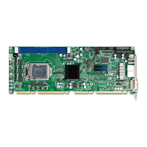
- Page 1 ROBO-8112VG2AR ROBO-8112VG2AR-Q87 Single Host Board User's Manual Version 1.0b Copyright © Portwell, Inc., 2014 All rights reserved. All other brand names are registered trademarks of their respective owners.
-
Page 2: Table Of Contents
Preface Table of Contents How to Use This Manual Chapter 1 System Overview....................1-1 1.1 Introduction........................1-1 1.2 Check List ........................1-2 1.3 Product Specification ....................1-3 1.4 System Configuration ....................1-5 1.5 System Architecture ......................1-7 Chapter 2 Hardware Configuration..................2-1 2.1 Jumper Setting .......................2-1 2.2 Connector Allocation ....................2-3 Chapter 3 System Installation....................3-1 3.1 Intel®... -
Page 3: How To Use This Manual
Preface How to Use This Manual The manual describes how to configure your ROBO-8112VG2AR series system to meet various operating requirements. It is divided into five chapters, with each chapter addressing a basic concept and operation of Single Host Board. - Page 4 Preface Notice SBC Handling and Installation Notice Handling and Installing SBC Caution: Do not just hold any single side of the SBC; hold evenly on both sides! Heavy processor cooler may bend the SBC when SBC being held just on one side. The bending may cause soldering or components damaged.
- Page 5 Preface Fix your SBC in System Caution: Suggest your S.I or vendor to use a metal bracket to hold/fix the desktop or server grade SBC to avoid the vibration damage during transportation. Heavy processor cooler may bend the SBC when systems are during transportation without any holder. Example: 4U chassis : Use L type mental or plastic or rubber bracket to hold SBC.
-
Page 6: Chapter 1 System Overview
Chapter 1 System Overview Introduction ROBO-8112VG2AR series, the PICMG 1.3 SHB (Single Host Board) supports the Intel® 4th Generation Core i3/i5/i7 and Xeon E3-1200v3 series processors. The attractive Core i3/i5/i7 and Xeon E3-1200v3 family processors not only posses amazing parallel computing power but also support ECC /non-ECC memory . That makes the system more powerful. -
Page 7: Check List
ROBO-8112VG2AR series features: Support Intel® Xeon E3-1200v3 family/Core i3 processors on ROBO-8112VG2AR and 4th Generation Core i7/i5 processors on ROBO-8112VG2AR-Q87 in an LGA1150 socket Two 240-pin DDR3 ECC SDRAM DIMM socket, support for DDR3 1333/1066 DIMMs, up to 16GB system memory Intel®... -
Page 8: Product Specification
Main processor - Intel® Xeon E3-1200v3 family and 4th Generation Core i3 Processor on ROBO-8112VG2AR - Intel® 4th Generation Core i7/i5 Processor on ROBO-8112VG2AR-Q87 BIOS - Phoenix system BIOS with SPI Serial CMOS EEPROM with easy upgrade function ACPI, DMI, Green function and Plug and Play Compatible... - Page 9 Outline Dimension (L X W) - 338.5mm (13.33”) X 126.39mm (4.98”) Power Requirements - +12V (CPU)@ 3.56A - +12V (System+Device)@ 5.29A - +5V (System+ Device)@ 4.94A - Test Programs: BurnIn Test V6.0 - Run Time: Full loading 30 Min. ROBO-8112VG2AR User’s Manual...
-
Page 10: System Configuration
System Overview System Configuration System Configuration CPU Type Intel® Xeon® CPU E3-1275 V3 (ES) 3.50GHz L3:8M SBC BIOS Portwell, Inc. ROBO-8112VG2AR Rev.:R1.00.W0 (04182003) Memory WARIS DDR3 ECC UB-DIMM 1600 8GB*2 (hynix H5TQ4G83MFR) VGA Card Onboard Intel(R) HD Graphics P4600/P4700 VGA Driver Intel(R) HD Graphics P4600/P4700 Version 9.18.10.3071... -
Page 11: Mechanical Drawing
System Overview Mechanical Drawing ROBO-8112VG2AR User’s Manual... -
Page 12: System Architecture
System Overview System Architecture All of details operating relations are shown in ROBO-8112VG2AR series System Block Diagram. ROBO-8112VG2AR series System Block Diagram ROBO-8112VG2AR User’s Manual... -
Page 13: Chapter 2 Hardware Configuration
Hardware Configuration This chapter gives the definitions and shows the positions of jumpers, headers and connectors. All of the configuration jumpers on ROBO-8112VG2AR series are in the proper position. The default settings shipped from factory are marked with an asterisk ( ). - Page 14 2 x8 PCI Express (Support Two slot) Open (1-2 , 3-4) 1 x16 PCI Express (Support One slot) Note: ROBO-8112VG2AR can support one PCIEx16 or two PCIEx8 or one PCIEx8 + two PCIEx4. JP2: CMOS Clear PIN NO. Function...
-
Page 15: Connector Allocation
COM1 Serial Port 1 Connector External USB3 Connector J16/J20 General Purpose I/O Connector +12V Power Connector Connect to Ethernet RJ-45 Connector (LAN 2)WGI210AT Ethernet RJ-45 Connector (LAN 1)WGI217LM SMBus Connector SYSTEM FAN Power Connector POWER 4P For USB Power ROBO-8112VG2AR User’s Manual... - Page 16 USB3_RX3_DP USB3_RX3_DN 5V Dual J9: Internal USB3 Connector PIN No. Signal Description PIN No. Signal Description 5V Dual USB3_RX6_DN USB3_RX6_DP Ground USB3_TX6_DN USB3_TX6_DP Ground USB2_DN5 USB2_DP5 Ground USB2_DP4 USB2_DN4 Ground USB3_TX5_DP USB3_TX5_DN Ground USB3_RX5_DP USB3_RX5_DN 5V Dual ROBO-8112VG2AR User’s Manual...
- Page 17 Data7 Ground Acknowledge# Ground Busy Ground Paper Empty Ground Printer Select J6/J7: External USB Connector PIN No. Signal Description PIN No. Signal Description 5V Dual 5V Dual USB- USB- USB+ USB+ Ground Ground Key( no pin ) ROBO-8112VG2AR User’s Manual...
- Page 18 Ground Write Protect# Read Data# Ground Head Select# Disk Change# J13: External PS/2 Keyboard/Mouse Connector PIN No. Signal Description PIN No. Signal Description Mouse Data Keyboard Data Ground Ground PS2 Power PS2 Power Mouse Clock Keyboard Clock ROBO-8112VG2AR User’s Manual...
- Page 19 DSR (Data Set Ready) RXD (Receive Data) DATA+ RTS (Request to Send) TXD (Transmit Data) CTS (Clear to Send) DTR (Data Terminal Ready) RI (Ring Indicator) Ground Note: J15 (COM2) could be configurable as RS-232/422/485 with BIOS Setting. ROBO-8112VG2AR User’s Manual...
- Page 20 All General Purpose I/O ports can only apply to standard TTL ± 5% signal level (0V/5V), and each Fan J19 :+12V POWER Connector PIN No. Signal Description PIN No. Signal Description Ground Ground Ground Ground +12V +12V +12V +12V J23:SMBUS Connector PIN NO. Signal Description SMBus_CLK Ground SMBus_DAT ROBO-8112VG2AR User’s Manual...
- Page 21 J26:POWER 4P CONNECTOR for USB POWER PIN NO. Signal Description Ground Ground J27:Front Panel Pin HDR PIN No. Signal Description PIN No. Signal Description PWR_LED(+) Speaker(+) PWR_LED(-) J22 LAN1_ACT(+) J22 LAN1_ACT(-) Speaker(-) J21 LAN2_ACT(-) J21 LAN2_ACT(+) HDD_LED(+) HDD_LED(-) ROBO-8112VG2AR User’s Manual...
- Page 22 Description PIN No. Description PIN No. Description SHIELD1 SHIELD2 SHIELD3 DDCCLK SHIELD4 DDCDATA CLK+ HPDET CLK- Green Blue H_SYNC A_GND1 A_GND2 30: CPU Fan Connector PIN NO. Signal Description Ground +12V Fan on/off output Fan Speed control ROBO-8112VG2AR User’s Manual 2-10...
-
Page 23: Chapter 3 System Installation
Pin1 corner of the CPU Socket LGA-1150 CPU Yellow Triangle Pin1 of the CPU Alignment key Notch Please remember to locate the alignment keys on the CPU socket of the motherboard and the notches on the CPU. ROBO-8112VG2AR User’s Manual... - Page 24 System Installation LGA-1150 CPU Installation Steps Before install the CPU, please make sure to turn off the power first!! 1. Open the load lever. 2. Lift the load lever up to fully open ROBO-8112VG2AR User’s Manual...
- Page 25 3. Remove the plastic cap on the CPU socket. Before you install the CPU, always cover it to protect the socket pin. 4. After confirming the CPU direction for correct mating, put down the CPU in the socket housing frame. Note that alignment keys are matched. ROBO-8112VG2AR User’s Manual...
- Page 26 System Installation 5. Make sure the CPU has been seated well into the socket. If not, take out the CPU and reinstall. 6. Engage the load lever while pressing down lightly onto the load plate. ROBO-8112VG2AR User’s Manual...
-
Page 27: Main Memory
7. Push the CPU socket lever back into its locked position. Main Memory ROBO-8112VG2AR provide 2 x240 pin DIMM sockets (Dual Channel) which supports Dual channel 1333/1600 DDR3-SDRAM as main memory, non-register function. ROBO-8112VG2AR just supports ECC and Non-ECC memory. The maximum memory can be up to 16GB. -
Page 28: Installing The Single Board Computer
Step 1 : Check all jumpers setting on proper position Step 2 : Install and configure CPU and memory module at right position Step 3 : Place ROBO-8112VG2AR into the dedicated position in the system Step 4 : Attach cables to existing peripheral devices and secure it WARNING Please ensure that SBC is properly inserted and fixed by mechanism. -
Page 29: Intel® Proset Gigabit Ethernet Controlle
Please find Intel® WG1217LM and WG1210AT LAN driver in /Ethernet directory of ROBO-8112VG2AR CD-title. The driver supports Windows Win7 64-bits. 3.3.4 Audio Controller Please find Intel® High Definition Audio driver form ROBO-8112VG2AR CD-title. The driver supports Windows Win7 64-bits. 3.3.5 Intel® Active Management Technology (Intel® AMT) Please find the latest Intel®AMT 9.0 driver from ROBO-8112VG2AR CD-title. -
Page 30: Wdt Function
Below are some example codes, which demonstrate the use of WDT. #include <stdio.h> #include <conio.h> #include <dos.h> #define SIO_Port 0x2E #define SIO_Port2 0x4E #define GPIO_LDN 0x07 void Enter_IT872x_SIO() { outportb(SIO_Port, 0x87); outportb(SIO_Port, 0x01); outportb(SIO_Port, 0x55); outportb(SIO_Port, 0x55); ROBO-8112VG2AR User’s Manual... - Page 31 Set_Register(unsigned char offset, unsigned char value) { outportb(SIO_Port, offset); outportb(SIO_Port+1, value); printf("Write offset:%x = %x\n", offset, value); int main(void) { printf("test string\n"); Enter_IT872x_SIO(); Set_LDN(GPIO_LDN); Set_Register(0x72, 0xC0); Set_Register(0x73, 0x05); printf("System will reset in 5 seconds\n"); return 0; ROBO-8112VG2AR User’s Manual...
-
Page 32: Gpio
System Installation GPIO The ROBO-8112VG2AR provides 8 programmable input or output ports that can be individually configured to perform a simple basic I/O function. Users can configure each individual port to become an input or output port by programming register bit of I/O Selection. - Page 33 GPIO Test:\n"); //pin1 =11 //pin3 =12 //pin5 =47 //pin7 =50 //pin2 =14 //pin4 =35 //pin6 =36 //pin8 =37 Enter_IT872x_SIO(); Set_LDN(GPIO_LDN); //Enable GPIO //Or_Register(0xC0,0x46) //11,12,14 //Or_Register(0xC2,0xE0) //35,36,37 //Or_Register(0xC3,0x80) //47 //Or_Register(0xC4,0x01) //50 //Set Output Or_Register(0xC8,0x06); //11,12 Or_Register(0xCB,0x80); //47 ROBO-8112VG2AR User’s Manual 3-11...
- Page 34 (result==0){ printf("Test fail!!\n"); return 1; //output low outp(GPIO_Base+0,inp(GPIO_Base+0)&0xF9); //11,12 outp(GPIO_Base+3,inp(GPIO_Base+3)&0x7F); //47 outp(GPIO_Base+4,inp(GPIO_Base+4)&0xFE); //50 result=1; if ((inp(GPIO_Base+0)&0x10)!=0x00) result=0; if ((inp(GPIO_Base+2)&0xE0)!=0x00) result=0; if (result==0){ printf("Test fail!!\n"); return 1; /////////////////////////////////////////////////// //Set Input And_Register(0xC8,0xF9); //11,12 And_Register(0xCB,0x7F); //47 And_Register(0xCC,0xFE); //50 ROBO-8112VG2AR User’s Manual 3-12...
- Page 35 (result==0){ printf("Test fail!!\n"); return 1; //output low outp(GPIO_Base+0,inp(GPIO_Base+0)&0xEF); //14 outp(GPIO_Base+2,inp(GPIO_Base+2)&0x1F); //35,36,37 result=1; if ((inp(GPIO_Base+0)&0x06)!=0x00) result=0; //11,12 if ((inp(GPIO_Base+3)&0x80)!=0x00) result=0; //47 if ((inp(GPIO_Base+4)&0x01)!=0x00) result=0; //50 if (result==0){ printf("Test fail!!\n"); return 1; //getchar (); printf("Test Pass!!\n"); return 1; ROBO-8112VG2AR User’s Manual 3-13...
-
Page 36: Chapter 4 Bios Setup Information
Chapter 4 BIOS Setup Information ROBO-8112VG2AR is equipped with the Phoenix BIOS stored in Flash ROM. These BIOS has a built-in Setup program that allows users to modify the basic system configuration easily. This type of information is stored in CMOS RAM so that it is retained during power-off periods. -
Page 37: Main
Use this menu for basic system configurations, such as time, date etc. System Date The date format is <Day>, <Month> <Date> <Year>. Use [+] or [-] to configure system Date. System Time The time format is <Hour> <Minute> <Second>. Use [+] or [-] to configure system Time. ROBO-8112VG2AR User’s Manual... -
Page 38: Configuration
BIOS Setup Information Configuration Use this menu to set up the items of special enhanced features ROBO-8112VG2AR User’s Manual... - Page 39 If you select ‘Enabled’ the diagnostic splash screen always displays during boot. If you select ‘Disabled’ the diagnostic splash screen does not displays unless you press HOTKEY during boot. Choices: Disabled, Enabled. Diagnostic Summary Screen Display the Diagnostic summary screen during boot. Choices: Disabled, Enabled. ROBO-8112VG2AR User’s Manual...
- Page 40 BIOS Setup Information Allow Hotkey in S4 resume Enable hotkey detection when system resuming from Hibernate state. Choices: Disabled, Enabled. UEFI Boot Enable the UEFI boot. Choices: Disabled, Enabled. PCI/PCIE Configuration Configure PCI/PCI Express slot. ROBO-8112VG2AR User’s Manual...
- Page 41 FEG0 PEG0 – Gen X Configure PFG0 B0:D0:F0 Speed. Choices: Gen1, Gen2, Gen3 FEG1 PEG1 – Gen X Configure PFG1 B0:D0:F1 Speed. Choices: Gen1, Gen2, Gen3 FEG2 PEG2 – Gen X Configure PFG2 B0:D0:F2 Speed. Choices: Gen1, Gen2, Gen3 ROBO-8112VG2AR User’s Manual...
- Page 42 BIOS Setup Information ICH PCI Express Configuration DMI Link ASPM Control The control of active state Power Management on both NB side of the DMI Link. Choices: Disabled, L0s, L1, L0sL1. ROBO-8112VG2AR User’s Manual...
- Page 43 Select PCIe Speed to Gen1 or Gen2 Choices: Auto, Gen1, Gen2. ASPM Control PCIe Active State Power Management settings. Choices: Disabled, L0S, L1, L0S And L1, Auto. HOT PLUG PCI Express Hot Plug Enabled/Disabled. Choices: Disabled, Enabled. ROBO-8112VG2AR User’s Manual...
- Page 44 Root PCI Express System Error on Non-Fatal Error Enable/Disable. Choices: Disabled, Enabled. SECE Root PCI Express System Error on Correctable Error Enable/Disable. Choices: Disabled, Enabled. PME Interrupt Root PCI Express PME Interrupt Enable/Disable. Choices: Disabled, Enabled. PME SCI PCI Express PME SCI Choices: Disabled, Enabled. ROBO-8112VG2AR User’s Manual...
- Page 45 SLP_S4 Assertion stretch Enable Choices: Disabled, Enabled Wake system with Fixed Time Enable or disable system wake on alarm event. When Enabled, system will wake on the hr::min::sec specified. Choices: Disabled, Enabled Wake up By Ring Choices: Enabled, Disabled. ROBO-8112VG2AR User’s Manual 4-10...
- Page 46 Select the number of physical cores to enable in each processor package. Choices: All, 1. Limit CPUID Maximum Disabled for Windows XP. Choices: Disabled, Enabled. Execute Disabled Bit Enabled Execute Disabled functionality. Also known as Data Execution Prevention (DEP). Choices: Disabled, Enabled. ROBO-8112VG2AR User’s Manual 4-11...
- Page 47 Choices: Disabled, Enabled. C-States Choices: Disabled, Enabled. VT-x When enabled, a VWM can utilize the additional hardware capabilities provided by Vanderpool Technology. Choices: Disabled, Enabled. Local x2APIC Choices: Disabled, Enabled. LAN Configuration Configure onboard LAN device. ROBO-8112VG2AR User’s Manual 4-12...
- Page 48 Control LAN Boot ROM (PXE) function. Choices: Disabled, Enabled. Intel WG1210AT GbE LAN Enabled/Disabled Intel WG1210AT LAN. Choices: Disabled, Enabled. Wake on LAN Enabled/Disabled Wake on LAN Function. Choices: Disabled, Enabled. Chipset Configuration Configure Chipset provide feature. ROBO-8112VG2AR User’s Manual 4-13...
- Page 49 To Enable the PEG Slot. Choices: Disabled, Enabled. PEG ASPM Control ASPM Support for the PEG Device. This has mp effect if PEF is not the current active sevice. Choices: Disabled, Auto, ASPM L0s, ASPM L1, ASPM L0sL1. ROBO-8112VG2AR User’s Manual 4-14...
- Page 50 Choices: 1GB, 1.25GB, 1.5GB, 1.75GB, 2GB, 2.25GB, 2.5GB, 2.75GB, 3GB, 3.25GB. Memory Frequency Maximum Memory Frequency Selections in Mhz. Choices: Auto, 1067, 1333, 1600, 1867, 2133. Memory ECC Support Enabled/Disabled Memory ECC support function. Choices: Enabled, Disabled. ROBO-8112VG2AR User’s Manual 4-15...
- Page 51 BIOS Setup Information SB Azalia Config SB Azalia Config Parameters. Azalia Control Detection of the Azalia device. Choices: Disabled, Enabled. Azalia PME Enabled Enabled/Disabled PME for Azalia.. Choices: Disabled, Enabled. ROBO-8112VG2AR User’s Manual 4-16...
- Page 52 Choices: 128MB, 256MB, 512MB. DVMT Pre-Allocated Select DVMT 5.0 Pre-Allocated Graphics Memory size used by the Internal Graphics Device. Choices: 0M, 32M, 64M, 96M, 128M, 160M, 192M, 224M, 256M, 288M, 320M , 352M, 384M, 416M, 448M, 480M, 512M. ROBO-8112VG2AR User’s Manual 4-17...
- Page 53 Configure SATA controller and view detected HDD Information. SATA Controller (s) Determines how SATA controllers (s) operate. Choices: Disabled, Enabled. Launch Storage OpROM Enable or Disable Boot Option for Legacy Mass Storage Devices with Option ROM. Choices: Enabled, Disabled. ROBO-8112VG2AR User’s Manual 4-18...
- Page 54 Choices: Disabled, Enabled. External Port External SATA Support. Choices: Disabled, Enabled. SATA Device Type Select ”Solid State Drive” only if a Solid State Drive is connected to this SATA port. Choices: Hard Disk Driver, Solid State Driver. ROBO-8112VG2AR User’s Manual 4-19...
- Page 55 Configure USB controller and other advanced setting. Legacy USB Support Enables Legacy USB support. AUTO option disables legacy support if no USB devices are connected. DISABLE option will keep USB devices available only for EFI applications. Choices: Enabled, Disabled. ROBO-8112VG2AR User’s Manual 4-20...
- Page 56 BIOS Setup Information PCH USB Configuration Control each of the USB ports disabling. USB Ports Per-Port Disable Choices: Enabled, Disabled. ROBO-8112VG2AR User’s Manual 4-21...
- Page 57 BIOS Setup Information ME Configuration Configure Management Engine Technology Parameters. Intel (R) ME Enable/Disable Intel (R) Management Engine. Choices: Enabled, Disabled. ROBO-8112VG2AR User’s Manual 4-22...
- Page 58 Serial Port 1-2 Choices: Disabled, 2F8/IRQ3, 3F8/IRQ4. COM2 Configuration Select Com2 Configuration. Choices: RS-232, RS422, RS485. Parallel Address Choices: Disabled, 378/IRQ7. Watch Dog Timer Select Choices: Disabled, 15 secs, 30 secs, 1 min, 2 mins, 3 mins. ROBO-8112VG2AR User’s Manual 4-23...
-
Page 59: Hardware Monitor
BIOS Setup Information Hardware Monitor Provide on board sensor reading information. (Show only) CPU Fan Feature ROBO-8112VG2AR User’s Manual 4-24... - Page 60 Choices: 25, 30, 35, 40, 45, 50, 55, 60, 65, 70, 75, 80, 85 ℃. Fan Full Speed Temp Choices: 50, 55, 60, 65, 70, 75, 80, 85 ℃. Serial Port Console Configuration Configure console redirection on serial port. Console Redirection Control Console Redirection enable/disable. Choices: Enabled, Disabled ROBO-8112VG2AR User’s Manual 4-25...
- Page 61 BIOS Setup Information SMBIOS Event Log Clears SMBIOS events. Choices: Enter ROBO-8112VG2AR User’s Manual 4-26...
-
Page 62: Security
Press Enter to type Supervisor Hint String. Set User Password Set or clear the User account’ password. Supervisor Hint String Press Enter to type User Hint String. Min. password length Set the minimum number of characters for password (1-20). ROBO-8112VG2AR User’s Manual 4-27... -
Page 63: Boot
Boot Priority Order Keys used to view or configure devices: ↑ and ↓ arrows Select a device. ‘+’ and ‘-‘move the device up or down. ‘Shift + 1’ enabled or disables a device. ‘Del’ deletes an unprotected device. ROBO-8112VG2AR User’s Manual 4-28... -
Page 64: Exit
Load settings for optimized boot time and system performance. Discard Changes Load the original value of this boot time. Not the default Setup value. Save Changes Save all changes of all menus, but do not reset sys ROBO-8112VG2AR User’s Manual 4-29... -
Page 65: Chapter 5 Troubleshooting
Chapter 5 Troubleshooting This chapter provides a few useful tips to quickly get ROBO-8112VG2AR running with success. As basic hardware installation has been addressed in Chapter 2, this chapter will focus on system integration issues, in terms of BIOS setting, and OS diagnostics. -
Page 66: Bios Setting
BIOS setting back to the initial factory configuration. It is recommended to do this so you can be sure the system is running with the BIOS setting that Portwell has highly endorsed. As a matter of fact, users can load the default BIOS setting any time when system appears to be unstable in boot up sequence. - Page 67 IRQ 15 Usable IRQ 【Unassigned】 It is then very easy to find out which IRQ resource is ready for additional peripherals. If IRQ resource is not enough, please disable some devices listed above to release further IRQ numbers. ROBO-8112VG2AR User’s Manual...
-
Page 68: Faq
Troubleshooting Installation Problem Question: How to update the BIOS file of the ROBO-8112VG2AR? Answer: Please visit web site of the Portwell download center as below hyperlink and registeran account. http://www.portwell.com.tw/support/ Input your User name and password to log in the download center. Select the "Search download" to input the keyword "ROBO-8112VG2AR". -
Page 69: System Memory Address Map
System Memory Address Map Each On-board device in the system is assigned a set of memory addresses, which also can be identical of the device. The following table lists the system memory address used for your reference. ROBO-8112VG2AR User’s Manual...
Need help?
Do you have a question about the ROBO-8112VG2AR and is the answer not in the manual?
Questions and answers