
Related Manuals for Portwell ROBO-8712VLA


Summary of Contents for Portwell ROBO-8712VLA
- Page 1 ROBO-8712VLA Single Board Computer User's Manual P/N: B8980850 Version 1.4 Copyright © Portwell, Inc., 2004. All rights reserved. All other brand names are registered trademarks of their respective owners.
-
Page 2: Table Of Contents
Preface Table of Contents How to Use This Manual Chapter 1 System Overview.......................1-1 1.1 Introduction..........................1-1 1.2 Check List ............................. 1-2 1.3 Product Specification ........................1-2 1.3.1 Mechanical Drawing......................1-6 1.4 System Architecture ........................1-6 Chapter 2 Hardware Configuration ...................2-1 2.1 Jumper Setting .......................... -
Page 3: How To Use This Manual
BIOS. In addition, POST checkpoint list will give you a guide of trouble-shooting. Chapter 5: Troubleshooting. This chapter provides you a few useful tips to quickly get your ROBO-8712VLA running with no failure. As basic hardware installation has been addressed in Chapter 3, this chapter will basically focus on system integration issues, in terms of backplane setup, BIOS setting, and OS diagnostics. -
Page 4: Ec Declaration Of Conformity
EN 61000-4-2 (1995) EN 61000-4-3 (1996) EN 61000-4-4 (1995) EN 61000-3-2 (1995) EN 61000-3-3 (1995) The following manufacturer is responsible for this declaration : Portwell, Inc. (Company Name) 3F, No.88, Sec. 1, Nei-Hu Rd., Taipei, Taiwan, R.O.C. (Company Address) Taipei, R.O.C. Place... - Page 5 Preface WARNING Remove Processor Caution: Do not pull out processor without opening socket handle! High viscosity thermal grease between processor and cooler will lead the processor be pulled out from socket when taking cooler off. This action may damage processor socket, which will cause poor contact between CPU &...
-
Page 6: Chapter 1 System Overview
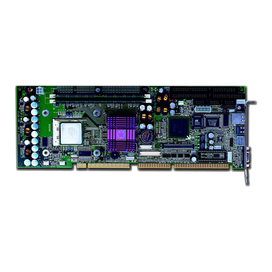
Chapter 1 System Overview Introduction ROBO-8712VLA is a cost effective and high integration Pentium 4 applied computing platform. It provides innovative, high integration, high quality Single Board Computers in the applied computing market. The board is based on Intel 845GV chipset and support Intel latest high performance processor, Intel Socket 478 Pentium®... -
Page 7: Check List
System Overview Check List The ROBO-8712VLA package should cover the following basic items: One ROBO-8712VLA single board computer One serial port kit with two COM ports One Parallel port cable kit One FDC cable One IDE cable One Y-cable cable for PS/2 keyboard and mouse... - Page 8 - Parallel Port Support one parallel port with SPP, EPP and ECP modes - USB Interface USB 2.0 compliant Support three USB (Universal Serial Bus) ports for high-speed I/O peripheral devices One on bracket; two with pin header ROBO-8712VLA User’s Manual...
- Page 9 Auxiliary I/O Interfaces System reset switch, external speaker, Keyboard lock and HDD active LED, etc. Power Good On-Board power good generator with 200 ms to 300 ms reset duration CPU Cooling Fan Support one 3-pin header with wafer ROBO-8712VLA User’s Manual...
- Page 10 On-board 68-pin PCI connector Support one additional PCI daughter board Optional daughter Board Ultra 160 SCSI (AIC 7892 chipset) - Support Portwell Proprietary PCI connector - Support one 68-pin SCSI interface - SCSI data transfers up to 160MB/sec Physical and Environmental requirements - Outline Dimension (L x W) 338.5mm (13.33”) X 122mm (4.8”)
-
Page 11: Mechanical Drawing
CPU provides better performance to many applications. The PCI-to-ISA bridge supports a standard 16-bit ISA bus interface which is applied for all slower I/O operations. In ROBO-8712VLA, it supports DiskOnChip (DOC) for M-systems Flash disk. ROBO-8712VLA User’s Manual... - Page 12 System Overview There is one on-board PCI Fast Ethernet via RJ-45 Ports to support full functionality of ROBO-8712VLA AIO SBC (All-In-One Single Board Computer). The on-board 68-pin PCI connector supports one additional PCI daughter board for further extension. Intel Pentium...
-
Page 13: Chapter 2 Hardware Configuration
( ). Jumper Setting For users to customize ROBO-8712VLA’s features. In the following sections, Short means covering a jumper cap over jumper pins; Open or N/C (Not Connected) means removing a jumper cap from jumper pins. -
Page 14: Connector Allocation
Connect to Chassis Standalone Power Connector Only for standard one ATX Power Button Interface Connect to Chassis Reset Button Connector Connect to Chassis DVO Power Connector Optional DVO Connector -1 Optional DVO Connector -2 Optional Front SMBus Connector ROBO-8712VLA User’s Manual... - Page 15 Ground Ground Density Select 1 Ground Index# Ground Motor ENA# Ground Drive Select B# Ground Drive Select A# Ground Motor ENB# Ground Direction# Ground Step# Ground Write Data# Ground Write Gate# Ground Track 0# Ground Write Protect# ROBO-8712VLA User’s Manual...
- Page 16 RI (Ring Indicator) Notes: 1) J8 is fixed as RS-232 2) J9 is configurable as RS-232/422/485 with jumper JP2 J10: External Wake On LAN Connector PIN No. Signal Description 5VSB Ground External WOL Signal Input (Active low) ROBO-8712VLA User’s Manual...
- Page 17 Ground Busy Ground Paper Empty Ground Printer Select J12: IrDA Connector PIN No. Signal Description IRRX Ground IRTX J13: PS/2 Keyboard/Mouse Connector PIN No. Signal Description Mouse Data Keyboard Data Ground 5V Dual Mouse Clock Keyboard Clock ROBO-8712VLA User’s Manual...
- Page 18 Signal Description MIC with Reference Voltage Analog Ground Line-in Left Channel Analog Ground Line-in Right Channel Analog Ground Line-out Left Channel Analog Ground Line-out Right Channel Note: The Reference Voltage on MIC signal offers 2.25V~2.75V with 5mA drive ROBO-8712VLA User’s Manual...
- Page 19 Green Blue Monitor ID0 (MONID0) (5V I/F) Ground Ground Ground Ground Ground Monitor ID1 (MONID1) (5V I/F) VGA DDC Data (5V I/F) Horizontal Sync. (HSYNC) (5V I/F) Vertical Sync. (VSYNC) (5V I/F) VGA DDC Clock (5V I/F) ROBO-8712VLA User’s Manual...
- Page 20 Ground AD24 AD25 AD26 AD27 AD28 AD29 AD30 AD31 Ground C/BE#0 C/BE#1 C/BE#2 C/BE#3 FRAME# TRDY# IRDY# Ground STOP# DEVSEL# PERR# SERR# REQ#4 GNT#4 REQ#5 GNT#5 Ground PCI Clock1 PCI Clock2 PCIRST# LOCK# IRQ#A IRQ#B IRQ#C IRQ#D ROBO-8712VLA User’s Manual...
- Page 21 Through invert amplitude respected to GPIO port, each open-drain DO port can stand maximum fan out for up to 100mA, rather than 12mA direct driven by GPIO port. J26: 12V CPU Supplementary Connector PIN No. Signal Description Ground Ground +12V +12V ROBO-8712VLA User’s Manual...
- Page 22 ATX 5V Stand-by (5VSB) ATX Power On Control (PS-ON) Ground J30: Power LED and Keyboard Lock Connector PIN No. Signal Description +5V (470 Ohm pull-up for power LED+) Ground (For Power LED-) Keyboard Lock Signal Input (Active low) Ground ROBO-8712VLA User’s Manual 2-10...
- Page 23 Pull-high 1K Ohm to +5V Power Button Signal Input (Active high) J33: Reset Button Connector PIN No Signal Description Reset Signal Input (Active low) Ground J34: DVO Power Connector PIN No. Signal Description +12V +3.3V Ground Ground ROBO-8712VLA User’s Manual 2-11...
- Page 24 J36: DVO Connector-2 (Factory Optional for Panel Display Kit only); not populated on the standard module PIN No. Signal Description PIN No. Signal Description DVOBD0 DVOBD1 DVOBD2 DVOBD3 DVOBD4 DVOBD5 DVOBD6 DVOBD7 DVOBD8 DVOBD9 DVOBD10 DVOBD11 DVOBCLK DVOBCLK# DVOBVSYNC DVOBHSYNC DVOBFLDSTL DVOBCCLKINT Ground +3.3V ROBO-8712VLA User’s Manual 2-12...
- Page 25 Hardware Configuration J38: Front SMBus Connector PIN No. Signal Description SMBCLK Ground SMBDATA ROBO-8712VLA User’s Manual 2-13...
-
Page 26: Chapter 3 System Installation
4) Follow the steps of installing a CPU to change to another one or place handling bar to close the opened socket. Configuring System Bus ROBO-8712VLA will automatically detect the CPU used. CPU speed of Intel P4 can be detected automatically. ROBO-8712VLA User’s Manual... -
Page 27: Main Memory
M-systems Flash Disk ROBO-8712VLA reserves one 32-pin DIP sockets for installing M-systems Flash disk from 2MB to 288MB. This operation structure is running with pure ISA-bus without PnP (Plug and Play) function. Before installing, make sure that I/O address jumper setting is set on right position to prevent unworkable system due to I/O resource conflict. -
Page 28: Installing The Single Board Computer
3.4.1 Chipset Component Driver The chipset on ROBO-8712VLA is a new chipset that a few old operating systems might not be able to recognize. To overcome this compatibility issue, for Windows Operating Systems such as Windows-95/98/98SE/2000, please install its INF before any of other Drivers are installed. -
Page 29: On-Board Fast Ethernet Controller
3.4.3 On-board Fast Ethernet Controller Drivers Support Please find Intel ICH4 LAN driver in /Ethernet directory of ROBO-8712VLA CD- title. The drivers support Windows-NT 4.0, Windows-98/98SE/ME, Windows-2000, Windows-XP, and Linux. LED Indicator (for LAN status) ROBO-8712VLA provides three LED indicators to report 82801BA MAC Fast Ethernet interfaces status. -
Page 30: Clear Cmos Operation
Additionally, there are maximum 2 seconds of counting tolerance that should be considered into user’ application program. For more information about WDT, please refer to Winbond W83627HF data sheet. ROBO-8712VLA User’s Manual... -
Page 31: On-Board Usb 2.0 Controller
Time-out Value Register 1) 0x00 -- Time-out Disable 2) 0x01~0xFF -- Value for counting down On-Board USB 2.0 Controller Drivers Support Please find Intel ICH4 USB driver in /USB20 directory of ROBO-8712VLA CD-title. The drivers support Windows-2000 and Windows-XP. ROBO-8712VLA User’s Manual... -
Page 32: Panel Display Output (Factory Optional Only)
System Installation Panel Display Output (Factory Optional only) This is a factory optional function through a Portwell proprietary VDO connector and a 5-pin shouted header for power control/source of backlight system. There are two LCD panel interfaces can provided in this system, TMDS and LVDS are two interfaces available on different panel kit. - Page 33 If a port is assigned to be an input port, then its respective bit can be read only. Notes: 1) All the Buffered Digital Outputs are open-drain amplified form corresponding GPIO ports. 2) Some other functions may occupy the lower nibble of the registers. Altering any content in lower nibble will be undesired. ROBO-8712VLA User’s Manual...
-
Page 34: Chapter 4 Bios Setup Information
Chapter 4 BIOS Setup Information ROBO-8712VLA is equipped with the AWARD BIOS stored in Flash ROM. This BIOS has a built-in Setup program that allows users to modify the basic system configuration easily. This type of information is stored in CMOS RAM so that it is retained during power-off periods. -
Page 35: Main Menu
BIOS Setup Information Main Menu Once you enter ROBO-8712VLA AWARD BIOS CMOS Setup Utility, you should start with the Main Menu. The Main Menu allows you to select from eleven setup functions and two exit choices. Use arrow keys to switch among items and press <Enter>... -
Page 36: Standard Cmos Setup Menu
Press <Enter> to enter the sub menu of Master menu (described in 4.4 detailed options Table) IDE Primary Options are in its sub Press <Enter> to enter the next page Slave menu for detail hard drive settings (described in 4.4 Table) ROBO-8712VLA User’s Manual... - Page 37 All, but Disk/Key Base Memory Displays the amount of conventional memory detected during boot up Extended Displays the amount of extended Memory memory detected during boot up Total Memory Displays the total memory available in the system ROBO-8712VLA User’s Manual...
-
Page 38: Ide Adaptors Setup Menu
Choose the access mode for this hard disk Large Auto Capacity Auto Display your disk Disk drive capacity (Approximated). drive size Note that this size is usually slightly greater than the size of a formatted disk given by a disk checking program. ROBO-8712VLA User’s Manual... -
Page 39: Advanced Bios Feature
OS Select For DRAM > 64MB [Non-OS2] Report No FDD For WIN 95 [No] Small Logo(EPA) Show [Disabled] ↑↓→←: Move Enter: Select +/-/PU/PD: Value F10: Save ESC: Exit F1: General Help F5: Previous Values F6: Fail-Safe Defaults F7: Optimized Defaults ROBO-8712VLA User’s Manual... - Page 40 The choice: Enabled, Disabled. Boot Up Floppy Seek Enabled tests floppy drives to determine whether they have 40 or 80 tracks The choice: Enabled, Disabled. Boot Up NumLock Status Select power on state for NumLock. The choice: Off, On. ROBO-8712VLA User’s Manual...
- Page 41 Select OS/2 only if you are running SO/2 operating system with greater than 64MB of RAM on the system. The choice: Non-OS2, OS2. Report No FDD for WIN 95 The choice: No, Yes. Small Logo (EPA) Show The choice: Enabled, Disabled. ROBO-8712VLA User’s Manual...
-
Page 42: Advanced Chipset Feature
Such a scenario might well occur if your system had mixed speed DRAM chips installed so that greater delays may be required to preserve the integrity of the data held in the slower memory chips. ROBO-8712VLA User’s Manual... - Page 43 System BIOS Cacheable Selecting Enabled allows caching of the system BIOS ROM at F0000h-FFFFFh, resulting in better system performance. However, if any program writes to this memory area, a system error may result. The choice: Enabled, Disabled. ROBO-8712VLA User’s Manual 4-10...
- Page 44 Users can set the display memory size that shared from main memory. The choice: 1MB, 8MB. Boot Display The choice: Auto, CRT, TV, EFP. On board LAN Control Users can disable on board LAN function. The choice: Enabled, Disabled. ROBO-8712VLA User’s Manual 4-11...
-
Page 45: Integrated Peripherals
Midi Port IRQ [10] Watch Dog Timer Select [Disabled] DOC Memory Address Range [D8000-D9FFF] ↑↓→←: Move Enter: Select +/-/PU/PD: Value F10: Save ESC: Exit F1: General Help F5: Previous Values F6: Fail-Safe Defaults F7: Optimized Defaults ROBO-8712VLA User’s Manual 4-12... - Page 46 DOS, or Windows-NT with no USB driver loaded. The choice: Enabled, Disabled. USB Mouse Support This item allows you to enabled USB Mouse function under POST, BIOS Setup menu, DOS, or Window-NT with no USB driver loaded. The choice: Enabled, Disabled. ROBO-8712VLA User’s Manual 4-13...
- Page 47 In the event of “Power On Function” being configured as “Hot Key”, this item will be enabled for tuning. The choice: Ctrl-F1 to Ctrl-F12. Onboard FDC Controller This item allows you to enable/disable onboard Floppy disk controller. The choice: Enabled, Disabled. ROBO-8712VLA User’s Manual 4-14...
- Page 48 Use IR Pins The available choices are IR-Rx2Tx2/ RxD2, TxD2. The choice: IR-Rx2Tx2 / RxD2, TxD2. Onboard Parallel Port This item allows you to configure I/O address of the onboard parallel port. The choice: Disabled, 378/IRQ7, 278/IRQ5, 3BC/IRQ7. ROBO-8712VLA User’s Manual 4-15...
- Page 49 Watch Dog Timer Select This BIOS testing option is able to reset the system according to the selected table. The choice: Disabled, 10 Sec, 20 Sec, 30 Sec, 40 Sec, 1 Min, 2 Min, 4 Min. ROBO-8712VLA User’s Manual 4-16...
-
Page 50: Power Management Setup
Secondary IDE 0 [Disabled] Secondary IDE 1 [Disabled] FDD,COM,LPT Port [Disabled] PCI PIRQ[A-D]# [Disabled] ↑↓→←: Move Enter: Select +/-/PU/PD: Value F10: Save ESC: Exit F1: General Help F5: Previous Values F6: Fail-Safe Defaults F7: Optimized Defaults ROBO-8712VLA User’s Manual 4-17... - Page 51 Blank Screen This option only writes blanks to the video buffer. DPMS Initial display power management signaling. Video Off In Suspend This allows user to enable/disable video off in Suspend Mode. The choice: Yes, No. ROBO-8712VLA User’s Manual 4-18...
- Page 52 The choice: Disabled, Enabled. Power On by Ring When select “Enabled”, a system that is at soft-off mode will be alert to Wake-On- Modem signal. The choice: Enabled, Disabled. USB KB Wake-up From S3 The choice: Enabled, Disabled. ROBO-8712VLA User’s Manual 4-19...
- Page 53 The choice: Enabled, Disabled. PCI PIRQ[A-D]# This option can be used to detect PCI device activities. If they are activities, the system will go into sleep mode. The choice: Enabled, Disabled. ROBO-8712VLA User’s Manual 4-20...
-
Page 54: Pnp/Pci Configurations
Default is Disabled. Select Enabled to reset Extended System Configuration Data (ESCD) when you exit Setup if you have installed a new add-on and the system reconfiguration has caused such a serious conflict that the OS cannot boot. The choice: Enabled, Disabled. ROBO-8712VLA User’s Manual 4-21... - Page 55 Devices (S) using this INT: Display Cntrlr – Bus 0 Dev 2 Func 0 USB 1.0/1.1 UHCI Cntrlr – Bus 0 Dev29 Func 0. The choice: Auto, 3, 4, 5, 7, 9, 10, 11, 12, 14, 15. ROBO-8712VLA User’s Manual 4-22...
- Page 56 The choice: Auto, 3, 4, 5, 7, 9, 10, 11, 12, 14, 15. INT Pin 8 Assignment Devices (S) using this INT: USB 2.0 EHCI Cntrlr – Bus 0 Dev 29 Func 7. The choice: Auto, 3, 4, 5, 7, 9, 10, 11, 12, 14, 15. ROBO-8712VLA User’s Manual 4-23...
-
Page 57: Pc Health Status
This item allows you to set a temperature above which the system will operate in lower speed immediately. Default setting is Disabled. This function will only with “ACPI” power management and “S3 (STR)” suspend type. The choice: Disabled, 60℃/140℉, 65℃/149℉, 70℃/158℉, 75℃/167℉. ROBO-8712VLA User’s Manual 4-24... -
Page 58: Frequency/Voltage Control
When you press <Enter> on this item you get a confirmation dialog box with a message similar to: Load Optimized Defaults (Y/N) ? N Pressing ‘Y’ loads the default values that are factory settings for optimal performance system operations. ROBO-8712VLA User’s Manual 4-25... -
Page 59: Supervisor/User Password Setting
Security option (see Section 3). If the Security option is set to “System”, the password will be required both at boot and at entry to Setup. If set to “Setup”, prompting only occurs when trying to enter Setup. ROBO-8712VLA User’s Manual 4-26... -
Page 60: Exiting Selection
Pressing <Enter> on this item asks for confirmation: Quit Without Saving (Y/N)? N This allows you to exit Setup without storing in CMOS any change. The previous selections remain in effect. This exits the Setup utility and restarts your computer. ROBO-8712VLA User’s Manual 4-27... -
Page 61: Chapter 5 Troubleshooting
BIOS setting, and OS diagnostics. Backplane Setup Backplane ROBO-8712VLA is a full-sized SBC, and therefore is only able to run on PICMG PCI/ISA Backplane. P4 Power connector ROBO-8712VLA requires power drawing from at least two connectors. The CPU supplementary power connector (J26) should be connected at all time for this P4 system to run properly. - Page 62 Step4: Please find the J29 4-pin ATX Power Control Connector on the right part of ROBO-8712VLA in white color. You will also see a mark with “J29” on the lower side of J29 header. Connect the 4-pin ATX power control cable with this J29 header.
- Page 63 Q: In addition to the above description, is there anything to do to finish up an ATX system? A: Yes. ROBO-8712VLA needs to be configured to support ATX function for the above cabling. Please move jumper JP3 to 3-5 short and 4-6 short (support ATX function).
-
Page 64: Onboard Hardware Installation
Troubleshooting Q: How can I build up an AT system using ATX power supply A: Do not forget to move JP3 of ROBO-8712VLA back to 1-3 short and 2-4 short (support AT function). If the ATX power supply has a switch, such as ORION-300ATX, do not remove the jumper of backplane connector in step 1, and use the power supply switch as the system power on switch. - Page 65 BIOS optimal default, thank you for doing so. However, this will force the BIOS to pick up the default CPU core/bus ratio as well. It needs to be emphasized again that ROBO-8712VLA does not have switch or jumper to configure CPU core/bus ratio. This is done through BIOS automatically. Please check in the “Frequency/Voltage Control”...
-
Page 66: Bios Setting
BIOS setting that Portwell has highly endorsed. As a matter of fact, users can load the default BIOS setting any time when system appears to be unstable in boot up sequence. -
Page 67: Os Diagnostics
Please proceed to do so and restart your Windows. Devices with removed drivers will be automatically detected again. The drivers will be loaded automatically, if drivers have been included in the system database, else you will be asked to provide driver source for installation. ROBO-8712VLA User’s Manual... - Page 68 By default, any Windows OS starts with 640 x 480 with 16 colors display. The display driver provided in ROBO-8712VLA product CDROM can be installed into operating system to maximize the VGA performance. If you are using a monitor that Microsoft®...
- Page 69 7. Network setup within Windows-NT 4.0 is not as easy as within Windows-95/98. Special familiarity and care are required for a successful installation. Note: Please visit our technical web site at http://www.portwell.com.tw For additional technical information, which is not covered in this manual. ROBO-8712VLA User’s Manual...
Need help?
Do you have a question about the ROBO-8712VLA and is the answer not in the manual?
Questions and answers