
Related Manuals for Portwell ROBO-8717VG2A


Summary of Contents for Portwell ROBO-8717VG2A
- Page 1 ROBO-8717VG2A Single Board Computer User's Manual P/N: B8981400 Version 1.0A Copyright © Portwell, Inc., 2006. All rights reserved. All other brand names are registered trademarks of their respective owners.
-
Page 2: Table Of Contents
3.6 SMBus ............................3-7 3.7 On-Board USB 2.0 Controller..................... 3-7 3.8 GPIO .............................. 3-8 3.8.1 Pin assignment........................3-8 3.8.2 ROBO-8717VG2A GPIO Programming Guide.............. 3-8 3.8.3 Example ..........................3-10 Chapter 4 BIOS Setup Information....................4-1 4.1 Entering Setup..........................4-1 4.2 Main Menu ........................... 4-2 4.3 Standard CMOS Setup Menu .................... -
Page 3: How To Use This Manual
Preface How to Use This Manual The manual describes how to configure your ROBO-8717VG2A system to meet various operating requirements. It is divided into five chapters, with each chapter addressing a basic concept and operation of Single Board Computer. Chapter 1 : System Overview. Presents what you have in the box and give you an overview of the product specifications and basic system architecture for this series model of single board computer. - Page 4 Preface WARNING Warning how to take while heavy cooler was installed; pin in processor socket is fragile and it shall be careful handle. Remove Processor Caution: Do not pull out processor without opening socket handle! High viscosity thermal grease between processor and cooler will lead the processor be pulled out from socket when taking cooler off.
-
Page 5: Chapter 1 System Overview
478 processor on single host board with up to 84W TDP. ROBO-8717VG2A, a PICMG 1.0 PCI/ISA single host board adopts Intel 965 chipset that supports up to Intel 1,066MHz FSB Core 2 Duo processor and 4GB DDR2-800 system memory. -
Page 6: Check List
Audio in/out, Watch-dog timer, 6 USB 2.0 ports (dual USB on bracket dedicated for keyboard & mouse; four internal ports) Check List The ROBO-8717VG2A package should cover the following basic items: One ROBO-8717VG2A single board computer Dual 7-pin SATA signal cable... -
Page 7: Product Specification
Support one 6-pin connector for PS/2 keyboard/mouse connection ATX Power Control Interface One 4-pin header to support ATX power control with Modem Ring-On and Wake-On-LAN function Auxiliary I/O Interfaces System reset switch, external speaker, Keyboard lock and HDD active LED, etc ROBO-8717VG2A User’s Manual... - Page 8 ‧OS: Microsoft Windows XP SP1 ‧Test Programs: 3D Mark 2001 PRO for loading VGA and Burning Test V3.0 for loading CPU ‧Connected Fans: Only CPU fan connected ‧Run Time: 10 minutes Operating Temperature: -5°C ~ 60°C (23°F ~ 140°F) ROBO-8717VG2A User’s Manual...
-
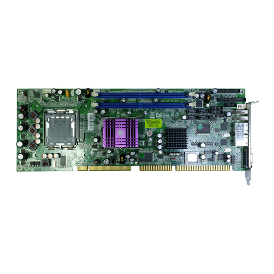
Page 9: Mechanical Drawing
System Overview Storage Temperature: -20°C ~ 80°C Relative Humidity: 0% ~ 95%, non-condensing 1.3.1 Mechanical Drawing ROBO-8717VG2A User’s Manual... -
Page 10: System Architecture
System Overview System Architecture ROBO-8717VG2A adopts Intel 965 GMCH (Graphics Memory Controller Hub) and ICH8 (I/O Controller Hub) chipset for processor, display, memory and peripheral I/O interfaces such as PCI Express, PCI bus, SATA ports, USB ports, and LPC (Low Pin Count) interface. -
Page 11: Chapter 2 Hardware Configuration
Hardware Configuration This chapter gives the definitions and shows the positions of jumpers, headers and connector. All of the configuration jumpers on ROBO-8717VG2A series are in the proper position. The default settings shipped from factory are marked with a star ( ). -
Page 12: Connector Allocation
COM2 Serial Port 2 Connector External PS/2 Keyboard/Mouse Connector General Purpose I/O Connector Parallel Port Connector For Power on/off, HDD Front panel Connector active LEDs, Power LED & Reset button External Speaker Connector ATX Power Control Connector ROBO-8717VG2A User’s Manual... - Page 13 Vertical Sync. (VSYNC) (5V I/F) VGA DDC Clock (5V I/F) J9: CPU Fan Connector PIN No. Signal Description Ground +12V Fan Control Fan Speed Detecting signal J10: +12V POWER Connector PIN No. Signal Description Ground Ground +12V +12V ROBO-8717VG2A User’s Manual...
- Page 14 Ground Write Gate# Ground Track 0# Ground Write Protect# Ground Read Data# Ground Head Select# Ground Disk Change# J31/J32/J28/J27: Primary/Secondary/3rd/4th SATA Connector PIN No. Signal Description Ground SATATX+ (SATATXP) SATATX- (SATATXN) Ground SATARX- (SATARXN) SATARX+ (SATARXP) Ground ROBO-8717VG2A User’s Manual...
- Page 15 PIN No. Signal Description MDI0+ (MDI0P) MDI0- (MDI0N) MDI1+ (MDI1P) MDI2+ (MDI2P) MDI2- (MDI2N) MDI1- (MDI1N) MDI3+ (MDI3P) MDI3- (MDI3N) J40: Audio CD-IN Connector PIN No. Signal Description CD-in Left Channel CD Ground CD Ground CD-in Right Channel ROBO-8717VG2A User’s Manual...
- Page 16 RXD (Receive Data) DATA+ TXD (Transmit Data) DTR (Data Terminal Ready) GND (Ground) DSR (Data Set Ready) RTS (Request to Send) CTS (Clear to Send) RI (Ring Indicator) Note: J43 (COM2) could be configurable as RS-232/422/485 with jumper JP5. ROBO-8717VG2A User’s Manual...
- Page 17 Auto Form Feed# Data 0 Error# Data 1 Initialization# Data 2 Printer Select IN# Data 3 Ground Data 4 Ground Data 5 Ground Data 6 Ground Data 7 Ground Acknowledge# Ground Busy Ground Paper Empty Ground Printer Select ROBO-8717VG2A User’s Manual...
- Page 18 Ground Note: The pull-high voltage of external speaker is limited at 5V maximum. J50: ATX Power Control Connector PIN No. Signal Description ATX Power Good Signal (PW-OK) ATX 5V Stand-by (5VSB) ATX Power On Control (PS-ON) Ground ROBO-8717VG2A User’s Manual...
-
Page 19: Chapter 3 System Installation
CPU gently until it fits into place. If this operation is not easy or smooth, don’t do it forcibly. You need to check and rebuild the CPU pin uniformly. Triangle mark is meaning first pin position; kindly assemble and take aim at notch of top and bottom between CPU and socket. ROBO-8717VG2A User’s Manual... -
Page 20: Main Memory
4) Follow the steps of installing a CPU to change to another one or place handling bar to close the opened socket. Configuring System Bus ROBO-8717VG2A series will automatically detect the CPU used. CPU speed of Intel Pentium D can be detected automatically. Main Memory ROBO-8717VG2A provides two DDR2-SDRAM DIMM sockets to support dual- channel &... -
Page 21: Installing The Single Board Computer
Step 1 : Check all jumpers setting on proper position Step 2 : Install and configure CPU and memory module on right position Step 3 : Place ROBO-8717VG2A into the dedicated position in the system Step 4 : Attach cables to existing peripheral devices and secure it WARNING Please ensure that SBC is properly inserted and fixed by mechanism. -
Page 22: Chipset Component Driver
3.3.1 Chipset Component Driver The chipset used on ROBO-8717VG2A series is relatively new which operating systems might not be able to recognize. To overcome this compatibility issue, for Windows Operating Systems such as Windows 2000/XP, please install its INF before any of other Drivers are installed. -
Page 23: On-Board Realtek Alc262 Device
2-channel audio function such as Line-in/Line-out/MIC via header on- board. Driver Support Please find Sound driver in \Audio of ROBO-8717VG2A driver CD-title. The drivers support Windows 2000 and Windows XP. Clear CMOS Operation The following table indicates how to enable/disable CMOS Clear Function hardware circuit by putting jumpers at proper position. -
Page 24: Wdt Function
// Enter Extended Function Mode outp(0x002E, 0x87); outp(0x002E, 0x87); // Assign Pin 89 to be a WDTO outp(0x002E, 0x2B); outp(0x002F, inp(0x002F) & 0xEF); // Select Logic Device 8 outp(0x002E, 0x07); outp(0x002F, 0x08); // Active Logic Device 8 outp(0x002E, 0x30); outp(0x002F, 0x01); ROBO-8717VG2A User’s Manual... -
Page 25: Smbus
SMB devices and external ACCESS bus devices. On-Board USB 2.0 Controller Drivers Support Please find Intel ICH8 USB driver in /USB20 directory of ROBO-8717VG2A CD-title. The drivers support Windows-2000/XP. ROBO-8717VG2A User’s Manual... -
Page 26: Gpio
3.8.2 ROBO-8717VG2A GPIO Programming Guide There are 8 GPIO pins on ROBO-8717VG2A series. These GPIO pins are from SUPER I/O (W83627HF) GPIO pins, and can be programmed as Input or Output direction. J25 pin header is for 8 GPIO pins and its pin assignment as following : J25_Pin1=GPIO1:from SUPER I/O_GPIO10 with Ext. - Page 27 Read LD7_CRF1h_Bit0; Read the status from GPIO10 pin (J25_Pin1) How to access W83627HF CR? In ROBO-8717VG2A, the EFER = 002Eh, and EFDR = 002Fh. EFER and EFDR are 2 IO ports needed to access W83627HF CR. EFER is the Index Port, EFDR is the Data Port.
-
Page 28: Example
; CR2A_Bit[7..2].P[1,1,1,1,1,1] ah,al dx,2eh al,2Ah dx,al dx,2fh al,ah dx,al dx,2eh al,07h ; Point to LDN7 dx,al dx,2fh al,07h dx,al dx,2eh ; Read CR30 al,30h dx,al dx,2fh al,dx al,01h ah,al dx,2eh ; CR30_Bit0.P1 al,30h dx,al dx,2fh al,ah dx,al ROBO-8717VG2A User’s Manual 3-10... - Page 29 ; Read LD7_CRF2 dx,al dx,2fh al,dx al,0efh ah,al dx,2eh al,0f2h ; LD7_CRF2_Bit4.P0 dx,al dx,2fh al,ah dx,al dx,2eh al,0f1h ; Read LD7_CRF1 dx,al dx,2fh al,dx al,0efh ah,al dx,2eh al,0f1h ; LD7_CRF1_Bit4.P0 dx,al dx,2fh al,ah dx,al ROBO-8717VG2A User’s Manual 3-11...
- Page 30 System Installation dx,2eh ; Exit Configuration Mode al,0AAh dx,al ROBO-8717VG2A User’s Manual 3-12...
-
Page 31: Chapter 4 Bios Setup Information
Chapter 4 BIOS Setup Information ROBO-8717VG2A is equipped with the AWARD BIOS stored in Flash ROM. This BIOS has a built-in Setup program that allows users to modify the basic system configuration easily. This type of information is stored in CMOS RAM so that it is retained during power-off periods. -
Page 32: Main Menu
BIOS Setup Information Main Menu Once you enter ROBO-8717VG2A series AWARD BIOS CMOS Setup Utility, a Main Menu is presented. The Main Menu allows user to select from eleven setup functions and two exit choices. Use arrow keys to switch among items and press <Enter> key to accept or bring up the sub-menu. -
Page 33: Standard Cmos Setup Menu
[EVG/VGA] Halt On [All, But Keyboard] Base Memory 640K Extended Memory 252928K Total Memory 253952K ↑↓→←: Move Enter: Select +/-/PU/PD: Value F10: Save ESC: Exit F1: General Help F5: Previous Values F6: Fail-Safe Defaults F7: Optimized Defaults ROBO-8717VG2A User’s Manual... - Page 34 Displays the amount of conventional memory detected during boot up Extended Displays the amount of extended Memory memory detected during boot up Total Memory Displays the total memory available in the system Note: is indicating default setting. ROBO-8717VG2A User’s Manual...
-
Page 35: Ide Adaptors Setup Menu
Set the number of cylinders for hard disk Head Min=0, Max=255 Set the number of read/write heads Precomp Min=0, Max=65535 **** Warning: Setting a value of 65535 means no hard disk Landing zone Min=0, Max=65535 **** Sector Min=0, Max=255 Number of sectors per track ROBO-8717VG2A User’s Manual... -
Page 36: Advanced Bios Features
Limit CPUID MaxVal [Disabled] Item Help Execute Disabled Bit [Enabled] Virtualization Technology [Enabled] Menu Level ↑↓→←: Move Enter: Select +/-/PU/PD: Value F10: Save ESC: Exit F1: General Help F5: Previous Values F6: Fail-Safe Defaults F7: Optimized Defaults ROBO-8717VG2A User’s Manual... - Page 37 <+> to move it up, or <-> to move it down the list. Press <ESC> to exit this menu. Bootable Add-in Cards Select SCSI Boot Ch x M (S). Select IDE Channel 0,1 Master or Salve Boot Ch x M. Select IDE Channel 2 or 3 Master Boot ROBO-8717VG2A User’s Manual...
- Page 38 If the system has two floppy drives, choose enable to assign physical driver B to logical drive A and Vice-Versa. The choice: Enabled, Disabled. Boot Up Floppy Seek Enabled tests floppy drives to determine whether they have 40 or 80 tracks. The choice: Enabled, Disabled. ROBO-8717VG2A User’s Manual...
- Page 39 Select OS/2 only if you are running SO/2 operating system with greater than 64MB of RAM on the system. The choice: Non-OS2, OS2. Report No FDD for WIN 95 The choice: No, Yes. Small Logo (EPA) Show The choice: Enabled, Disabled. ROBO-8717VG2A User’s Manual...
-
Page 40: Advanced Chipset Features
Advanced Chipset Features This section allows user to configure the system based on the specific features of the Intel 965 chipset for ROBO-8717VG2A. This chipset manages bus speeds and access to system memory resources, such as DRAM (DDR2 SDRAM) and the external cache. - Page 41 Enter: Select +/-/PU/PD: Value F10: Save ESC: Exit F1: General Help F5: Previous Values F6: Fail-Safe Defaults F7: Optimized Defaults Fan 1/2/3 Speed Monitor The choice: Enabled, Disabled. PEG/OnChip VGA Control The choice: Onchip VGA, PEG Port, Auto. ROBO-8717VG2A User’s Manual 4-11...
-
Page 42: Integrated Peripherals
IDE Secondary Slave UDMA [Auto] drive can support. SATA Mode [IDE] ↑↓→←: Move Enter: Select +/-/PU/PD: Value F10: Save ESC: Exit F1: General Help F5: Previous Values F6: Fail-Safe Defaults F7: Optimized Defaults ROBO-8717VG2A User’s Manual 4-12... - Page 43 DMA driver (Windows 95 OSR2 or a third-party IDE bus master driver). If your hard drive and system software both support Ultra DMA/33/66/100, select Auto to enable BIOS support. The choice: Auto, Disabled. ROBO-8717VG2A User’s Manual 4-13...
- Page 44 High rate for receiving / High rate for transmitting Hi, Lo High rate for receiving / Low rate for transmitting Lo, Hi Low rate for receiving / High rate for transmitting Lo, Lo Low rate for receiving / Low rate for transmitting ROBO-8717VG2A User’s Manual 4-14...
- Page 45 Switch to ECP + EPP mode EPP Mode Select Select different version of EPP mode. The choice: EPP1.7, EPP1.9. (Default EPP1.7) ECP Mode Use DMA Select a proper DMA channel for ECP mode. The choice: 3, 1. (Default 3) ROBO-8717VG2A User’s Manual 4-15...
- Page 46 DOS, or Windows-NT with no USB driver loaded. The choice: Enabled, Disabled. USB Mouse Function [Enabled] or [Disabled] legacy support of USB Mouse. The choice: Enabled, Disabled. USB Storage Function [Enabled] or [Disabled] legacy support of USB Mass storage. The choice: Enabled, Disabled. ROBO-8717VG2A User’s Manual 4-16...
-
Page 47: Power Management Setup
Enter: Select +/-/PU/PD: Value F10: Save ESC: Exit F1: General Help F5: Previous Values F6: Fail-Safe Defaults F7: Optimized Defaults ACPI Function This item allows you to enable/disable the Advanced Configuration and Power Management (ACPI). The choice: Enabled, Disabled. ROBO-8717VG2A User’s Manual 4-17... - Page 48 Video Off In Suspend This allows user to enable/disable video off in Suspend Mode. The choice: Yes, No. Suspend Type Two options are available : Stop Grant and PwrOn Suspend. The choice: Stop Grant, PwrOn Suspend. ROBO-8717VG2A User’s Manual 4-18...
- Page 49 This item allows users to enable/disable the resume by alarm function. When “Enabled” is selected, system using ATX power supply could be powered on if a customized time and day is approached. The choice: Enabled, Disabled. ROBO-8717VG2A User’s Manual 4-19...
- Page 50 The choice: Enabled, Disabled. PWRON After PWR-Fail This item allows user to configure the power status of using ATX power supply after a serious power loss occurs. System automatically restores Power back System stays at Power-Off Former-Str ROBO-8717VG2A User’s Manual 4-20...
-
Page 51: Pnp/Pci Configurations
Default is Disabled. Select Enabled to reset Extended System Configuration Data (ESCD) when you exit Setup if you have installed a new add-on and the system reconfiguration has caused such a serious conflict that the OS cannot boot. The choice: Enabled, Disabled. ROBO-8717VG2A User’s Manual 4-21... - Page 52 Legacy ISA for devices compliant with the original PC AT bus specification, PCI/ISA PnP for devices compliant with the plug and play standard whether designed for PCI or ISA bus architecture. The choice: Enabled, Disabled. Maximum Payload Size The choice: 128. ROBO-8717VG2A User’s Manual 4-22...
-
Page 53: Pc Health Status
F6: Fail-Safe Defaults F7: Optimized Defaults Auto Detect DIMM/PCI Clk The choice: Enabled, Disabled. Spread Spectrum This item allows user to enable/disable the spread spectrum modulate. The choice: Enabled, Disabled. COU Host/SRC/PCI Clock The choice: Default. ROBO-8717VG2A User’s Manual 4-23... -
Page 54: Default Menu
To disable a password, just press <Enter> when prompted to enter the password. A message will confirm the password will be disabled. Once the password is disabled, the system will reboot and Setup can be entered freely. ROBO-8717VG2A User’s Manual 4-24... -
Page 55: Exiting Selection
Pressing <Enter> on this item asks for confirmation: Quit Without Saving (Y/N)? N This allows user to exit Setup without storing in CMOS any change. The previous selections remain in effect. This exits the Setup utility and restarts your computer. ROBO-8717VG2A User’s Manual 4-25... -
Page 56: Chapter 5 Troubleshooting
OS diagnostics. Hardware Quick Installation Backplane ROBO-8717VG2A is a full-sized Signal Board Computer, and therefore is only able to run on PICMG PCI/ISA backplane. To know whether your backplane is PICMG PCI/ISA backplane, please contact with vendor or manufacturer. -
Page 57: Bios Setting
To make sure that you have a successful start with ROBO-8717VG2A series, it is recommended, when going with the boot-up sequence, to hit “DEL” key and enter the BIOS setup menu to tune up a stable BIOS configuration so that you can wake up your system far well. - Page 58 IRQ #15 Secondary IDE Controller It is then very easy to find out which IRQ resource is ready for additional peripherals. If IRQ resource is not enough, please disable some devices listed above to release further IRQ numbers. ROBO-8717VG2A User’s Manual...
-
Page 59: Faq
PCI device, backplane, and so on. If the system still cannot boot up, please fill out RMA from which is provides on Portwell website, and then send back to Portwell RMA. - Page 60 Question: I forget my password of system BIOS, what am I supposed to do? Answer: You can simply short 2-3 pins on JP4 to clean your password. Note: Please visit our technical web site at http://www.portwell.com.tw For additional technical information, which is not covered in this manual. ROBO-8717VG2A User’s Manual...
- Page 61 D54A – D7FE High RAM D7FF – D7FF 0.1K Unused D800 – E7FF Page Frame E800 – E800 0.1K Unused E801 – EAFF High RAM EB00 – EFFF Unused F000 – FFFF System ROM First 64K Extended ROBO-8717VG2A User’s Manual...
- Page 62 Usable IRQ IRQ 10 [Unassigned] Usable IRQ IRQ 11 [Unassigned] Usable IRQ IRQ 12 System ROM IBM Mouse Event IRQ 13 System ROM Coprocessor Error IRQ 14 System ROM Hard Disk Event IRQ 15 VIDE-CDD Usable IRQ ROBO-8717VG2A User’s Manual...
Need help?
Do you have a question about the ROBO-8717VG2A and is the answer not in the manual?
Questions and answers