
Related Manuals for Portwell ROBO-8920VG2


Summary of Contents for Portwell ROBO-8920VG2
- Page 1 ROBO-8920VG2 Single Host Board P/N: B8981410 Version 1.2 Copyright © Portwell, Inc., 2007. All rights reserved. All other brand names are registered trademarks of their respective owners.
-
Page 2: Table Of Contents
Preface Table of Contents How to Use This Manual Chapter 1 System Overview.......................1-1 1.1 Introduction..........................1-1 1.2 Check List ............................. 1-2 1.3 Product Specification ........................1-2 1.3.1 Mechanical Drawing......................1-4 1.4 System Architecture ........................1-5 Chapter 2 Hardware Configuration ...................2-1 2.1 Jumper Setting .......................... -
Page 3: How To Use This Manual
Preface How to Use This Manual The manual describes how to configure your ROBO-8920VG2 system to meet various operating requirements. It is divided into five chapters, with each chapter addressing a basic concept and operation of Single Board Computer. Chapter 1 : System Overview. Presents what you have in the box and give you an overview of the product specifications and basic system architecture for this series model of single board computer. -
Page 4: Chapter 1 System Overview
62W that similar to dual PIII processor. More than that, the Xeon processor LV also supports dual-core technology. ROBO-8920VG2, the PICMG 1.3 SHB supports dual Dual-Core Xeon processor LV (four cores) adopts Intel E7520 and 6300ESB chipset. The board equipped four... -
Page 5: Check List
System Overview Check List The ROBO-8920VG2 package should cover the following basic items: One ROBO-8920VG2 Single Host Board Dual high-efficiency processor coolers One Serial port & Printer port cable kit (2.0mm pitch) One FDC cable (2.0mm pitch) One IDE cable... - Page 6 System Monitoring Feature Monitor CPU temperature, system temperature and major power sources, etc Bracket Support dual Ethernet port with 2 indicators, dual USB ports, and one CRT port Outline Dimension (L X W): 338.58mm (13.33”) X 126.39mm (4.98”) ROBO-8920VG2 User’s Manual...
-
Page 7: Mechanical Drawing
‧Test Programs: 3D Mark 2001 PRO for loading VGA and Burning Test V4.0 for loading CPU ‧Connected Fans: Only CPU fan connected ‧Run Time: 30 minutes Operating Temperature: -5°C ~ 60°C (23°F ~ 140°F) Storage Temperature: -20°C ~ 80°C Relative Humidity: 0% ~ 95%, non-condensing 1.3.1 Mechanical Drawing ROBO-8920VG2 User’s Manual... -
Page 8: System Architecture
System Overview System Architecture ROBO-8920VG2 adopts Intel dual-processor server chipset, MCH (Memory Controller Hub) – E7520, and ICH (I/O Controller Hub) – 6300ESB. E7520 supports Intel Xeon processor LV, ECC & registered DDR2 400 system memory up to 8GB on four DIMM sockets, and three configurable PCI Express x8 links. -
Page 9: System Overview
X8 PCI-EXPRESS BUS B PCI-E BUS B CHANNEL B X8 PCI-EXPRESS BUS C PCI-E BUS C HI 1.5/ A R7000 PCI-X PICMG 1.3 GD FINGER PS/2 SUPER I/O KB/MOUSE COM Port PRT Port ROBO-8920VG2 System Block Diagram ROBO-8920VG2 User’s Manual... -
Page 10: Chapter 2 Hardware Configuration
Hardware Configuration This chapter gives the definitions and shows the positions of jumpers, headers and connectors. All of the configuration jumpers on ROBO-8920VG2 are in the proper position. The default settings shipped from factory are marked with an asterisk ( ). -
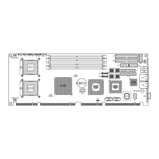
Page 11: Connectors
Gigabit Ethernet Indication (ACT/LINK) 4x1 pin header Header Intruder Indication Header 2x1 pin header Power On/Off Header (AT MODE) 2x1 pin header Second IDE Connector DDRII A-Channel PS/2 Keyboard/Mouse Connector DDRII B-Channel Primary IDE Connector DDRII A-Channel ROBO-8920VG2 User’s Manual... - Page 12 Chassis Fan Power Connector Pin Assignments of Connectors J1 : Power LED & Key-lock Header PIN No. Signal Description Power LED Positive Power LED Negative Key-lock Signal Ground J2 : External Speaker Header PIN No. Signal Description Speaker Signal Ground ROBO-8920VG2 User’s Manual...
- Page 13 Data 6 Data 9 Data 5 Data 10 Data 4 Data 11 Data 3 Data 12 Data 2 Data 13 Data 1 Data 14 Data 0 Data 15 Ground DMA REQ Ground IOW# Ground IOR# Ground IOCHRDY Pull-down ROBO-8920VG2 User’s Manual...
- Page 14 Data 3 Data 12 Data 2 Data 13 Data 1 Data 14 Data 0 Data 15 Ground DMA REQ Ground IOW# Ground IOR# Ground IOCHRDY Pull-down DMA ACK# Ground INT REQ ATA_SEL CS0# CS1# HDD Active# Ground ROBO-8920VG2 User’s Manual...
- Page 15 J13 : COM1 Serial Port PIN No. Signal Description Ground Ground Ground Ground J14 : COM2 Serial Port PIN No. Signal Description Ground Ground Ground Ground J15 : USB Port 1 Connector PIN No. Signal Description USBN USBP Ground Ground ROBO-8920VG2 User’s Manual...
- Page 16 Ground Acknowledge# Ground Busy Ground Paper Empty Ground Printer Select J18 : USB Port 2 Connector PIN No. Signal Description USBN USBP Ground Ground J19 : SATA Port 1 Connector PIN No. Signal Description Ground Ground Ground ROBO-8920VG2 User’s Manual...
- Page 17 Disk Change# J22 : SATA Port 1 Connector Signal Description PIN No. Ground Ground Ground J23 : Gigabit Ethernet Port A PIN No. Signal Description MD2+ MD0+ MD0- Termination To Ground MD2- MD3+ Termination To Ground MD1+ ROBO-8920VG2 User’s Manual...
- Page 18 SPEED 100 SPEED 1000 Termination To Ground Termination To Ground J25 : USB Port 3 & 4 Connector PIN No. Signal Description PIN No. Signal Description Ground Port3 USBN Ground Port3 USBP Port4 USBP Ground Port4 USBN Ground ROBO-8920VG2 User’s Manual...
- Page 19 Green Blue MONID0 Ground Ground Ground Ground Ground MONID1 Hsync Vsync Case Ground Case Ground J28 : Secondary VGA Connector PIN No. Signal Description Ground Ground Green Ground Ground Blue Ground Ground Hsync Ground Ground Vsync ROBO-8920VG2 User’s Manual 2-10...
- Page 20 J29 : DVI-D Display Connector PIN No. Signal Description Data0- Data0+ Ground Ground Data1- Data1+ Ground Ground Data2- Data2+ Ground Ground CLK- CLK+ DVIDDCLK DVIDDATA J30 : CompactFlash PIN No. Signal Description PIN No. Signal Description Ground CS#0 ATA_SEL IOCS16 ROBO-8920VG2 User’s Manual 2-11...
- Page 21 PIN No. Ground +12V Sensor Signal CPUFAN2 : CPU 2 Fan Power Connector Signal Description PIN No. Ground +12V Sensor Signal SYSFAN1 : Chassis Fan Power Connector Signal Description PIN No. Ground +12V Pull-up 4.7K ohm ROBO-8920VG2 User’s Manual 2-12...
-
Page 22: Chapter 3 System Installation
CPU gently until it fits into place. If this operation is not easy or smooth, don’t do it forcibly. You need to check and rebuild the CPU pin uniformly. Figure 2. CPU’s pin 1 mark ROBO-8920VG2 User’s Manual... -
Page 23: Main Memory
Sensor signal Main Memory ROBO-8920VG2 supports 4 x 240-pin DIMM sockets support 1.8V of dual-channel DDR2 400 with ECC & registered function, the maximum memory size can be up to 8GB. Auto detecting memory clock is according to BIOS CMOS settings. -
Page 24: Installing Single Board Computer
Step 1: Check all jumpers setting on proper position. Step 2: Install and configure CPU and memory module on right position. Step 3: Place ROBO-8920VG2 into the dedicated position in your system. Step 4: Attach cables to existing peripheral devices and secure it. -
Page 25: Chipset Component Driver
8920VG2 CD-title. 3.3.2 ATI Radeon 7000 graphics processor ROBO-8920VG2 equipped with ATI Radeon 7000 graphics processor to running on separated PCI bus. Default configuration with 32MB up to 64MB DDR video memory delivers enhanced 3D and 2D performance. Optional supports 64MB DDR video memory and dual VGA output. -
Page 26: Clear Cmos Operation
When the application is hung, it no longer refreshes the timer. The watchdog timer then times out and resets the SHB. For more information about WDT, please refer to Intel E6300ESB data sheet. http://www.intel.com ROBO-8920VG2 User’s Manual... -
Page 27: Chapter 4 Bios Setup Information
Chapter 4 BIOS Setup Information ROBO-8920VG2 is equipped with the AWARD BIOS stored in Flash ROM. These BIOS has a built-in Setup program that allows users to modify the basic system configuration easily. This type of information is stored in CMOS RAM so that it is retained during power-off periods. -
Page 28: Main Menu
BIOS Setup Information Main Menu Once you enter ROBO-8920VG2 AWARD BIOS CMOS Setup Utility, you should start with the Main Menu. The Main Menu allows you to select from eleven setup functions and two exit choices. Use arrow keys to switch among items and press <Enter>... -
Page 29: Standard Cmos Setup Menu
BIOS default when system configuration could not detect SATA HDD. If user successful employs SATA hard disk, the device configuration would be showed upon diagnostic; please skip to 4.7 “Integrated peripheral” section, and refer the program to setting. ROBO-8920VG2 User’s Manual... - Page 30 All, but Disk/Key Displays the amount of conventional Base Memory 640K memory detected during boot up Extended Displays the amount of extended Memory memory detected during boot up Displays the total memory available in Total Memory the system ROBO-8920VG2 User’s Manual...
-
Page 31: Ide Adaptors Setup Menu
Access Mode Choose the access mode for this hard disk Large Auto Capacity Auto Display your disk Disk drive capacity (Approximated). drive size Note that this size is usually slightly greater than the size of a formatted ROBO-8920VG2 User’s Manual... - Page 32 Min = 0 **** Warning: Setting a value of 65535 Max = 65535 means no hard disk Landing zone Min = 0 **** Max = 65535 Sector Min = 0 Number of sectors per track Max = 255 ROBO-8920VG2 User’s Manual...
-
Page 33: Advanced Bios Feature
Agent wait time (min) Report No FDD For WIN 95 [No] Small Logo(EPA) Show [Disabled] ↑↓→←: Move Enter: Select +/-/PU/PD: Value F10: Save ESC: Exit F1: General Help F5: Previous Values F6: Fail-Safe Defaults F7: Optimized Defaults ROBO-8920VG2 User’s Manual... - Page 34 By combining Execute Disable Bit with anti-virus, firewall, spy ware removal, e-mail filtering software, and other network security measures, IT managers can free IT resources for other initiatives. The choice: Enabled, Disabled. ROBO-8920VG2 User’s Manual...
- Page 35 No warning message will appear when anything attempts to access Disabled the boot sector or hard disk partition table. CPU L1 Cache/L2 Cache These two categories speed up memory access. However, it depends on CPU/chipset design. Enabled Enable Cache Disabled Disable Cache ROBO-8920VG2 User’s Manual...
- Page 36 Boot Up NumLock Status Select power on state for NumLock. The choice: Off, On. Gate A20 Option Fast-lets chipsets control Gate A20 and Normal – a pin in the keyboard controller controls Gate A20. The choice: Normal, Fast. ROBO-8920VG2 User’s Manual 4-10...
- Page 37 The choice: 1.1, 1.4. OS Select For DRAM > 64MB Select OS/2 only if you are running OS/2 operating system with greater than 64MB of RAM on the system. The choice: Non-OS2, OS2. Console Redirection The choice: Enabled, Disabled. ROBO-8920VG2 User’s Manual 4-11...
-
Page 38: Advanced Chipset Feature
[16 Min] DRAM Data integrity Mode [ECC] MCH Compliance Mode [Disabled] Memory RAS Feature [Standard] ↑↓→←: Move Enter: Select +/-/PU/PD: Value F10: Save ESC: Exit F1: General Help F5: Previous Values F6: Fail-Safe Defaults F7: Optimized Defaults ROBO-8920VG2 User’s Manual 4-12... - Page 39 The choice: 4, 8, 16, 32 Min. DRAM Data Integrity Mode The choice: Non-ECC, ECC. MCH Compliance Mode The choice: Enabled, Disabled. Memory RAS Feature Select special feature of DIMM Sparing or Mirror The choice: Standard, sparing, Mirror. ROBO-8920VG2 User’s Manual 4-13...
-
Page 40: Integrated Peripherals
ESC: Exit F1: General Help F5: Previous Values F6: Fail-Safe Defaults F7: Optimized Defaults Note: If user changes “On Chip Serial ATA” default to become “Enhance Mode”, you will perceive that shadow item could be selectable. ROBO-8920VG2 User’s Manual 4-14... - Page 41 PATA and SATA are combined. Max. Of 2 IDE drives in each Combined Mode channel. Enable both SATA and PATA. Max. Of 6 IDE drives are Enhanced Mode Supported. SATA Only SATA is operating in legacy mode. ROBO-8920VG2 User’s Manual 4-15...
- Page 42 DOS, or Windows-NT with no USB driver loaded. The choice: Enabled, Disabled. USB Mouse Support This item allows you to enabled USB Mouse function under POST, BIOS Setup menu, DOS, or Window-NT with no USB driver loaded. The choice: Enabled, Disabled. ROBO-8920VG2 User’s Manual 4-16...
- Page 43 There are four different modes for the onboard parallel port: Switch to SPP mode Switch to EPP mode Switch to ECP mode ECP + EPP Switch to ECP + EPP mode Normal Switch to Normal mode ROBO-8920VG2 User’s Manual 4-17...
-
Page 44: Power Management Setup
F10: Save ESC: Exit F1: General Help F5: Previous Values F6: Fail-Safe Defaults F7: Optimized Defaults ACPI Function This item allows you to enable/disable the Advanced Configuration and Power Management. The choice: Enabled, Disabled. (Default Enabled) ROBO-8920VG2 User’s Manual 4-18... - Page 45 When enabled and after the set time of system inactivity, all devices except the CPU will be shut off. The choice: Disabled, 1 Min, 2 Min, 4 Min, 8 Min, 12 Min, 20 Min, 30 Min, 40 Min, and 1 Hour. ROBO-8920VG2 User’s Manual 4-19...
- Page 46 “Enabled” is selected, system using ATX power supply could be powered on if a customized time and day is approached. The choice: Enabled, Disabled. When user sets the default at “Enabled”, he will be able to adjust both items of Date (of Month) Alarm and Time (hh:mm:ss) Alarm. ROBO-8920VG2 User’s Manual 4-20...
- Page 47 The choice: Enabled, Disabled. PCI PIRQ[A-D]# This option can be used to detect PCI device activities. If they are activities, the system will go into sleep mode. The choice: Enabled, Disabled. ROBO-8920VG2 User’s Manual 4-21...
-
Page 48: Pnp/Pci Configurations
BIOS can automatically configure the entire boot and plug and play compatible devices. If you choose Auto, you cannot select IRQ DMA and memory base address fields, since BIOS automatically assigns them. The choice: Auto (ESCD), Manual. ROBO-8920VG2 User’s Manual 4-22... -
Page 49: Pc Health Status
Smart Fan Spin UP Time [250ms] Switch Acoustics By CPUFAN [Disabled] X Smart Fan Ramp Rate 35 secs ↑↓→←: Move Enter: Select +/-/PU/PD: Value F10: Save ESC: Exit F1: General Help F5: Previous Values F6: Fail-Safe Defaults F7: Optimized Defaults ROBO-8920VG2 User’s Manual 4-23... -
Page 50: Frequency/Voltage Control
ESC: Exit F1: General Help F5: Previous Values F6: Fail-Safe Defaults F7: Optimized Defaults Spread Spectrum The choice: Enabled, Disabled. (Default Disabled) Spread Spectrum This item allows you to enable/disable the spread spectrum modulate The choice: Enabled, Disabled. (Default Disabled) ROBO-8920VG2 User’s Manual 4-24... -
Page 51: Default Menu
To disable a password, just press <Enter> when you are prompted to enter the password. A message will confirm the password will be disabled. Once the password is disabled, the system will boot and you can enter Setup freely. ROBO-8920VG2 User’s Manual 4-25... -
Page 52: Exiting Selection
Pressing <Enter> on this item asks for confirmation: Quit Without Saving (Y/N)? N This allows you to exit Setup without storing in CMOS any change. The previous selections remain in effect. This exits the Setup utility and restarts your computer. ROBO-8920VG2 User’s Manual 4-26... -
Page 53: Chapter 5 Troubleshooting
Chapter 5 Troubleshooting This chapter provides a few useful tips to quickly get ROBO-8920VG2 running with success. As basic hardware installation has been addressed in Chapter 2, this chapter will primarily focus on system integration issues, in terms of BIOS setting, and OS diagnostics. -
Page 54: Frequency Asking Questions (Faq)
BIOS Features”, and then enter “Hard Disk Boot Priority” to set HDD device boot priority. Q: If I wanna adopt CF card on ROBO-8920VG2, and equip one IDE HDD and one CD-ROM devices at simultaneously, why the BIOS diagnostic is not regular? A: Don’t adopt CF card and employ IDE HDD and CD-ROM at J7 (channel 1) -
Page 55: Bios Setting
To make sure that you have a successful start with ROBO-8920VG2, it is strongly recommended, when going with the boot-up sequence, to hit “DEL” key and enter the BIOS setup menu to tune up a stable BIOS configuration so that you can wake up your system far well. - Page 56 IRQ #15 Usable IRQ It is then very easy to find out which IRQ resource is ready for additional peripherals. If IRQ resource is not enough, please disable some devices listed above to release further IRQ numbers. ROBO-8920VG2 User’s Manual...
- Page 57 = Conventional memory ends at 636K = 9F00 – 9FBF VGA Graphics 9FC0 – 9FFF Unused A000 – AFFF VGA Text B000 – B7FF Video ROM B800 – BFFF Unused C000 – CAFF High RAM CB00 – EFFF 148K Unused F000 - FFFF ROBO-8920VG2 User’s Manual...
- Page 58 [Unassigned] Usable IRQ IRQ 10 [Unassigned] Usable IRQ IRQ 11 [Unassigned] Usable IRQ IRQ 12 DRMOUSE IBM Mouse Event IRQ 13 System ROM Coprocessor Error IRQ 14 System ROM Hard Disk Event IRQ 15 [Unassigned] Usable IRQ ROBO-8920VG2 User’s Manual...
Need help?
Do you have a question about the ROBO-8920VG2 and is the answer not in the manual?
Questions and answers