
Related Manuals for Raritan PX-1000 Series


Summary of Contents for Raritan PX-1000 Series
- Page 1 PX-1000/2000 Series User Guide Release 2.3 Copyright © 2012 Raritan, Inc. DPX2-1000-0D-v2.3-E March 2012 255-80-6105-00...
- Page 2 60950-1 or equivalent rating. Attempting to power non-rated devices may result in electric shock, fire, personal injury and death. WARNING! Do not use a Raritan product containing outlet relays to power large inductive loads such as motors or compressors. Attempting to power a large inductive load may result in damage to the relay.
-
Page 3: Safety Instructions
Safety Instructions 1. Installation of this product should only be performed by a person who has knowledge and experience with electric power. 2. Make sure the line cord is disconnected from power before physically mounting or moving the location of this product. 3. - Page 4 Raritan, Inc. © Copyright 2012 Raritan, Inc. All third-party software and hardware mentioned in this document are registered trademarks or trademarks of and are the property of their respective holders.
-
Page 5: Table Of Contents
Contents Safety Guidelines Safety Instructions Applicable Models xiii What's New in the Dominion PX User Guide Chapter 1 Introduction Product Models ..........................1 Product Features ........................... 1 Package Contents.......................... 3 Zero U Products........................4 1U Products ......................... 4 2U Products ......................... 4 Chapter 2 Rack-Mounting the PDU Rackmount Safety Guidelines ....................... - Page 6 Contents Preparing the Installation Site....................16 Filling Out the Equipment Setup Worksheet ..............16 Checking the Branch Circuit Rating...................16 Installing Cable Retention Clips on the Inlet (Optional) ...............17 Connecting the PDU to a Power Source ..................17 Configuring the Dominion PX ...................... 18 Connecting the Dominion PX to a Computer ..............19 Installing the USB-to-Serial Driver..................20 Connecting the Dominion PX to Your Network ..............21...
- Page 7 Contents Dominion PX Explorer Pane....................70 Setup Button ........................73 Status Bar .......................... 73 Add Page Icon ........................75 Logout Button ........................75 Data Pane.......................... 75 More Information .......................76 Viewing the Dashboard........................ 81 Alerted Sensors ......................... 81 Device Management ........................82 Displaying the PDU Information ..................82 Naming the PDU........................83 Modifying the Network Configuration.................84...
- Page 8 Contents Outlet Management ........................133 Naming Outlets ........................134 Checking Associated Circuit Breakers ................134 Outlet Switching.......................135 Setting the Default Outlet State ..................137 Changing the Cycling Power-Off Period................139 Setting the Initialization Delay ..................141 Setting the Inrush Guard Delay ..................142 Setting the Outlet Power-On Sequence ................142 Setting the Outlet-Specific Power-On Delay ..............143 Setting Non-Critical Outlets and Load Shedding Mode...........144 Inlet and Circuit Breaker Management ..................147...
- Page 9 Contents Copying Configurations with Bulk Configuration ...............201 Saving a Dominion PX Configuration ................202 Copying a Dominion PX Configuration................203 Changing the Measurement Units .....................203 Managing the Webcam Images or Videos.................205 Configuring Webcams .....................205 Adjusting Image or Video Properties................206 Viewing the Webcam Images or Videos................206 Snapshot Storage......................208 Network Diagnostics ........................210 Pinging a Host .........................210...
- Page 10 Contents IP Configuration .......................234 LAN Interface Settings.....................235 Networking Mode......................235 Wireless Configuration ....................235 Network Service Settings ....................236 PDU Configuration......................236 Outlet Information ......................237 Inlet Information .......................238 Circuit Breaker Information....................239 Date and Time Settings ....................239 Environmental Sensor Information ..................240 Inlet Sensor Threshold Information .................241 Inlet Pole Sensor Threshold Information .................242 Circuit Breaker Sensor Threshold Information ..............243 Environmental Sensor Threshold Information ..............244...
- Page 11 Contents Turning Off the Outlet(s)....................377 Power Cycling the Outlet(s).....................378 Unblocking a User........................379 Resetting the Dominion PX......................379 Restarting the PDU......................380 Resetting to Factory Defaults ..................380 Network Troubleshooting......................380 Entering the Diagnostic Mode ..................381 Diagnostic Commands ....................381 Quitting the Diagnostic Mode ..................384 Querying Available Parameters for a Command ...............385 Retrieving Previous Commands ....................385 Automatically Completing a Command..................385 Logging out of CLI........................386...
- Page 12 Contents RF Code Energy Monitoring Solution ..................410 Appendix F Additional Dominion PX Information MAC Address..........................411 Locking Outlets and Cords ......................411 SecureLock™ Outlets and Cords ..................412 Button-Type Locking Outlets ...................413 Altitude Correction Factors ......................414 Data for BTU Calculation ......................414 CLI Command Applicability......................415 Show Commands ......................415 Configuration Commands....................416 Other Commands ......................418...
- Page 13 Applicable Models This user guide is applicable to the PX-1000 and PX-2000 series, whose model name follows the PX2-1nnn or PX2-2nnn format, where n is a number. Note: For information on PX2-3nnn, PX2-4nnn and PX2-5nnn series, see the "PX2-3000/4000/5000 Series" User Guide or online help. xiii...
- Page 14 What's New in the Dominion PX User Guide The following sections have changed or information has been added to the Dominion PX User Guide based on enhancements and changes to the equipment and/or user documentation. Installing the USB-to-Serial Driver (on page 20) Connecting Blade Extension Strips (on page 43) Connecting AMS-M2-Z Asset Sensors (Optional)
- Page 15 What's New in the Dominion PX User Guide Truncated Data in the Web Interface (on page 418) Please see the Release Notes for a more detailed explanation of the changes applied to this version of Dominion PX.
-
Page 16: Chapter 1 Introduction
The intended use of the Raritan Dominion PX is distribution of power to information technology equipment such as computers and communication equipment where such equipment is typically mounted in an equipment rack located in an information technology equipment room. - Page 17 The ability to turn off "non-critical" outlets and keep "critical" outlets turned on when the connected UPS enters the battery-powered mode (PX-2000 series supports this feature while PX-1000 series does not) Support for SNMP v1, v2, and v3 ...
-
Page 18: Package Contents
Support for both of IPv4 and IPv6 networking Support for Baytech BSNMP Zero configuration service advertisement support Wireless connection via a Raritan-provided wireless USB LAN adapter The ability to visually monitor the data center environment through a connected Logitech ®... -
Page 19: Zero U Products
The Dominion PX device Screws, brackets and/or buttons for Zero U A null-modem cable with DB9 connectors on both ends (Raritan number: 254-01-0006-00) (optional) Cable retention clips for the inlet (for some models only) Cable retention clips for outlets (for some models only) 1U Products ... -
Page 20: Chapter 2 Rack-Mounting The Pdu
Rack-Mounting the PDU Chapter 2 This chapter describes how to rackmount a Dominion PX device. To mount a Zero U PX-1000 series PDU, you can use either two buttons or L-brackets that Raritan provided. In This Chapter Rackmount Safety Guidelines ..............5 Circuit Breaker Orientation Limitation............5... -
Page 21: Mounting Zero U Models Using L-Brackets
Chapter 2: Rack-Mounting the PDU Mounting Zero U Models Using L-Brackets If your PDU has circuit breakers implemented, read Circuit Breaker Orientation Limitation (on page 5) before mounting it. To mount Zero U models using L-brackets: 1. Align the baseplates on the rear of the Dominion PX device. 2. -
Page 22: Mounting Zero U Models Using Button Mount
Chapter 2: Rack-Mounting the PDU 5. Using rack screws, fasten the Dominion PX device to the rack through the L-brackets. Mounting Zero U Models Using Button Mount If your PDU has circuit breakers implemented, read Circuit Breaker Orientation Limitation (on page 5) before mounting it. To mount Zero-U models using button mount: 1. - Page 23 Chapter 2: Rack-Mounting the PDU 2. Make the baseplates grasp the Dominion PX device lightly. Use the included L-shaped hex key to loosen the hex socket screws until the baseplate is "slightly" fastened. 3. Screw each mounting button in the center of each baseplate. The recommended torque for the button is 1.96 N·m (20 kgf·cm).
-
Page 24: Mounting Zero U Models Using Claw-Foot Brackets
Chapter 2: Rack-Mounting the PDU Mounting Zero U Models Using Claw-Foot Brackets If your PDU has circuit breakers implemented, read Circuit Breaker Orientation Limitation (on page 5) before mounting it. To mount Zero U models using claw-foot brackets: 1. Align the baseplates on the rear of the Dominion PX device. 2. -
Page 25: Mounting Zero U Models Using Two Rear Buttons
Chapter 2: Rack-Mounting the PDU 5. Using rack screws, fasten the Dominion PX device to the rack through the claw-foot brackets. Mounting Zero U Models Using Two Rear Buttons The following describes how to mount a PDU using two buttons only. If your PDU has circuit breakers implemented, read Circuit Breaker Orientation Limitation... - Page 26 Chapter 2: Rack-Mounting the PDU 3. Screw a button in the screw hole near the bottom. The recommended torque for the button is 1.96 N·m (20 kgf·cm). 4. Screw a button in the screw hole near the top. The recommended torque for the button is 1.96 N·m (20 kgf·cm).
-
Page 27: Mounting Zero U Models Using L-Brackets And Buttons
Chapter 2: Rack-Mounting the PDU Mounting Zero U Models Using L-Brackets and Buttons This section describes how to mount a PDU using L-brackets and two buttons. If your PDU has circuit breakers implemented, read Circuit Breaker Orientation Limitation (on page 5) before mounting it. To mount Zero U models using L-brackets and two buttons: 1. -
Page 28: Mounting 1U Or 2U Models
Align two oval-shaped holes of the rackmount bracket with two threaded holes on one side of the Dominion PX device. b. Secure the rackmount bracket with two of the Raritan-provided screws. Note: The appropriate oval-shaped hole locations of the rackmount... - Page 29 L-shaped hole. 4. Secure the cable-support bar with one of the Raritan-provided cap screws. 5. Repeat Steps 3 to 4 to secure the other end of the cable-support bar to the other rackmount bracket.
-
Page 30: Chapter 3 Installation And Configuration
3. Inspect the equipment carefully. If any of the equipment is damaged or missing, contact Raritan's Technical Support Department for assistance. 4. Verify that all circuit breakers on the Dominion PX device are set to ON. -
Page 31: Preparing The Installation Site
Chapter 3: Installation and Configuration Preparing the Installation Site 1. Make sure the installation area is clean and free of extreme temperatures and humidity. Note: If necessary, contact Raritan Technical Support for the maximum operating temperature for your model. See Maximum Ambient Operating Temperature (on page 387). -
Page 32: Installing Cable Retention Clips On The Inlet (Optional)
Chapter 3: Installation and Configuration Installing Cable Retention Clips on the Inlet (Optional) If your Dominion PX device is designed to use a cable retention clip, install the clip before connecting a power cord. A cable retention clip prevents the connected power cord from coming loose or falling off. -
Page 33: Configuring The Dominion Px
The computer must have a communications program such as HyperTerminal or PuTTY. For a serial connection, you need a null-modem cable with DB9 connectors on both ends (Raritan part number: 254-01-0006-00). Connect the Dominion PX device to a TCP/IP network that supports DHCP. -
Page 34: Connecting The Dominion Px To A Computer
Chapter 3: Installation and Configuration Connecting the Dominion PX to a Computer To configure the Dominion PX using a computer, it must be connected to the computer with an RS-232 serial interface. These diagrams show the serial port location on different types of PDUs. Zero U models: 1U models: 2U models:... -
Page 35: Installing The Usb-To-Serial Driver
A USB-to-serial driver named "Dominion Serial Console" is ® ® required for Microsoft Windows operating systems. Download the dominion-serial.zip driver file, which contains dominion-serial.inf and dominion-serial-setup.exe files, from the following URL on the Raritan website: http://www.raritan.com/support/dominion-px/2.2.0/dominion-px2 series-usb-serial-driver. To install the driver in Windows ® Vista and 7: 1. -
Page 36: Connecting The Dominion Px To Your Network
Chapter 3: Installation and Configuration On a CD disc with SP2 included, it is extracted from I386\SP2.CAB. On a CD without an SP, it is extracted from I386\DRIVER.CAB. 3. Connect the Dominion PX's USB cable to the computer. 4. - Page 37 USB LAN adapter and wireless network configuration meet the following requirements. Network type: 802.11n Protocol: WPA2 (RSN) Key management: WPA-PSK Encryption: CCMP (AES) Important: Currently only Raritan-provided wireless USB LAN adapters are supported. You may contact Raritan Technical Support for this information.
-
Page 38: Initial Network Configuration
At the Username prompt, type admin and press Enter. b. At the Password prompt, type raritan and press Enter. 5. You are prompted to change the password if this is the first time you log in to the Dominion PX. - Page 39 Chapter 3: Installation and Configuration where <mode> is either wired for wired connection (default) or wireless for wireless connection. b. For the wired network mode, you may configure the LAN interface settings. In most scenarios, the default setting (auto) works well and should not be changed unless required.
- Page 40 Chapter 3: Installation and Configuration To set Use this command Authentication network wireless authMethod method <method> where <method> is psk for Pre-Shared Key or eap for Extensible Authentication Protocol. network wireless PSK <psk> where <psk> is the PSK string. EAP outer network wireless authentication eapOuterAuthentication...
- Page 41 Chapter 3: Installation and Configuration To set Use this command IP protocol network ip proto <protocol> where <protocol> is v4Only for enabling IPv4, v6Only for enabling IPv6 or both for enabling both IPv4 and IPv6 protocols. IP address network ip returned by dnsResolverPreference the DNS...
- Page 42 Chapter 3: Installation and Configuration For the static IPv4 configuration, configure these parameters. To set Use this command Static IPv4 network ipv4 ipAddress <ip address address> where <ip address> is the IP address you want to assign. Subnet mask network ipv4 subnetMask <netmask>...
- Page 43 Chapter 3: Installation and Configuration where <option> is enable or disable. See the table below for the IPv6 commands for manually specifying DNS servers. For the static IPv6 configuration, you should configure the following parameters. Note that the IP address must follow the IPv6 format.
-
Page 44: Cascading The Pdus Via Usb
Chapter 3: Installation and Configuration Command Description show network Show network parameters. show network ip all Show all IP configuration parameters. Show all wireless parameters. show network wireless details (Perform this command only when you enable the wireless mode.) Tip: You can also type "show network wireless" to display a shortened version of wireless settings. - Page 45 Chapter 3: Installation and Configuration 2. Determine which device is used as the master device. The master device must be connected to the LAN via a standard Category 5e/6 UTP cable. 3. Connect the USB-A port of the master device to the USB-B port of another Dominion PX device via an USB cable.
- Page 46 Chapter 3: Installation and Configuration Number Device role Master device The first slave device The second slave device The third slave device Note: On a master device, the networking mode shows "Wired." On a slave device, the networking mode shows "Wired(USB)," which indicates it is connected to the LAN through a USB cascading configuration.
-
Page 47: Installing Cable Retention Clips On Outlets (Optional)
Chapter 3: Installation and Configuration Installing Cable Retention Clips on Outlets (Optional) If your Dominion PX device is designed to use a cable retention clip, install the clip before connecting a power cord. A cable retention clip prevents the connected power cord from coming loose or falling off. The use of cable retention clips is highly recommended for regions with high seismic activities, and environments where shocks and vibrations are expected. -
Page 48: Connecting Environmental Sensors (Optional)
"U". This allows gravity to keep the clip in place. 4. Repeat the same steps to install clips and power cords on the other outlets. Tip: Raritan also provides other mechanisms to securely hold the power cords in place. See Locking Outlets and Cords (on page 411). - Page 49 Raritan PX sensor hub Raritan environmental sensors 3. If there are any Raritan air flow sensors attached, make sure that sensor faces the source of the wind (such as a fan) in the appropriate orientation as indicated by the arrow on that sensor.
-
Page 50: About Contact Closure Sensors
Failure to follow installation and configuration instructions can result in false alarms or no alarms. Raritan makes no statement or claim that all third-party detectors/switches will work with DPX-CC2-TR. Connecting Third-Party Detectors/Switches to DPX-CC2-TR A DPX-CC2-TR unit provides two channels for connecting two third-party detectors/switches. - Page 51 Chapter 3: Installation and Configuration Note: Each button controls the spring of each corresponding termination point. 3. Fully insert each wire of both third-party detectors/switches into each termination point. Plug both wires of a detector/switch into the two termination points to the left.
- Page 52 Chapter 3: Installation and Configuration Normally Open: The open status of the connected detector/switch is considered normal. Normally Closed: The closed status of the connected detector/switch is considered normal. This is the default. 5. To set the Normal state for channel 2, repeat Step 4 for adjusting the other dip switch's setting.
-
Page 53: How To Connect Differential Air Pressure Sensors
To connect a differential air pressure sensor: 1. Plug one end of a Raritan-provided phone cable to the SENSOR port of the Dominion PX device. 2. Plug the other end of this phone cable to the IN port of the differential air pressure sensor. -
Page 54: Combining Asset Sensors
RJ-45 connector while the slave one does not. The following diagram illustrates some asset sensors. Note that Raritan provides more types of asset sensors than the diagram. Number... - Page 55 Chapter 3: Installation and Configuration Make sure that the U-shaped sheet metal adjacent to the male DIN connector is inserted into the rear slot of the master asset sensor. Screw up the U-shaped sheet metal to reinforce the connection. 2.
-
Page 56: Connecting Asset Sensors To The Dominion Px
Chapter 3: Installation and Configuration Connecting Asset Sensors to the Dominion PX You need both of asset sensors and asset tags for tracking IT devices. Asset tags, which are affixed to IT devices, provide an ID number for each IT device, while the asset sensors transmit ID numbers and positioning information to the connected Dominion PX device. - Page 57 Chapter 3: Installation and Configuration The Dominion PX device supplies power to the asset sensor assembly through the Category 5e/6 cable. All LEDs on the asset sensor assembly may cycle through different colors during the power-on process if the asset sensor's firmware is being upgraded by the Dominion PX device.
-
Page 58: Connecting Blade Extension Strips
For blade servers, which are contained in a single chassis, you can use a blade extension strip to track individual blade servers. Raritan's blade extension strip functions similar to a Raritan asset sensor but requires a tag connector cable for connecting to a tag port on the regular asset sensor or AMS-M2-Z. - Page 59 Chapter 3: Installation and Configuration Note: Each tag pot on the blade extension strip is labeled a number, which is displayed as the slot number in the Dominion PX's web interface. To install a blade extension strip: 1. Connect the tag connector cable to the blade extension strip. ...
- Page 60 Chapter 3: Installation and Configuration b. Plug the tag connector of the asset tag into the tag port on the blade extension strip. 4. Repeat the above step until all blade servers in the chassis are connected to the blade extension strip via asset tags. 5.
-
Page 61: Connecting Ams-M2-Z Asset Sensors (Optional)
Chapter 3: Installation and Configuration Connecting AMS-M2-Z Asset Sensors (Optional) The AMS-M2-Z is a special type of asset sensor that functions the same as regular MASTER asset sensors with the following differences. It provides two RJ-45 connectors. Multiple AMS-M2-Z asset sensors can be daisy chained. ... - Page 62 4. Repeat Step 2 to connect IT devices to the other AMS-M2-Z's in the chain via the asset tags. AMS-M2-Z Daisy-Chain Limitations There are some limitations when daisy chaining the AMS-M2-Z asset sensors. The limitations vary according to the Raritan product model connected to the first AMS-M2-Z. Models Daisy-chain limitations ...
-
Page 63: Connecting A Logitech Webcam (Optional)
Chapter 3: Installation and Configuration Connecting a Logitech Webcam (Optional) ® ® The Dominion PX supports Logitech QuickCam Pro 9000 webcams connected to it, allowing you to view video or snapshots of the area surrounding the webcam. The Dominion PX supports up to one webcam. After connecting a webcam, you can visually monitor environmental conditions near the Dominion PX through the web interface from anywhere. -
Page 64: Connecting A Schroff Lhx Heat Exchanger (Optional)
Chapter 3: Installation and Configuration Connecting a Schroff LHX Heat Exchanger (Optional) ® To remotely monitor and administer the Schroff LHX-20 or LHX-40 heat exchangers through the Dominion PX device, you must establish a connection between the heat exchanger and the Dominion PX device. Note that only the PDUs whose model names begin with PX2 support the LHX heat exchangers. -
Page 65: Chapter 4 Using The Pdu
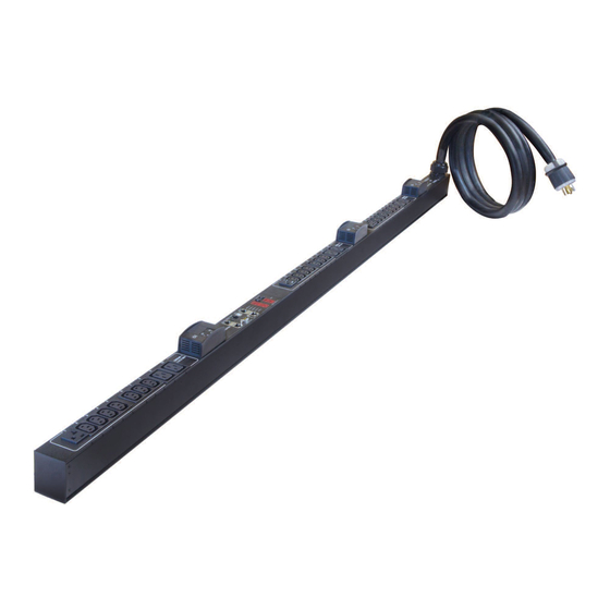
Reset button Power Cord Most of Raritan PDUs come with an installed power cord, which is ready to be plugged into an appropriate receptacle for receiving electricity. Such devices cannot be rewired by the user. Connect each Dominion PX device to an appropriately rated branch circuit. -
Page 66: Connection Ports
Chapter 4: Using the PDU PX-1000 Series These PDUs are NOT outlet-switching capable models so all outlets are always in the ON state. Outlet LEDs are not available. PX-2000 Series These models are outlet-switching capable PDUs. A small LED is adjacent to each outlet to indicate the state of the relay board. - Page 67 LHX-20 or LHX-40 device through a RJ-45 to RS-232 cable provided by Schroff, OR -- Connection to a Raritan asset management sensor, which allows you to track the locations of the IT devices on the rack. See Connecting the Asset Management Sensor (Optional) (on page 38).
- Page 68 DB9 connectors on both ends to connect the Dominion PX device to the computer. SENSOR Connection to Raritan's environmental sensors. For Zero U products, a sensor hub is required if you want to connect more than one environmental sensor.
-
Page 69: Led Display
Chapter 4: Using the PDU LED Display The LED display is located on the side where outlets are available. These diagrams show the LED display on different types of PDUs. Note that the LED display might slightly vary according to the PDU you purchased. - Page 70 Chapter 4: Using the PDU The LED display consists of: A row displaying three digits A row displaying two digits Up and Down buttons Five LEDs for measurement units A Zero U model can detect its own orientation through the built-in tilt sensor and automatically changes the direction of the alphanumeric digits shown on the LED display for easy reading.
- Page 71 Chapter 4: Using the PDU LEDs for Measurement Units Five small LED indicators are on the LED display: four measurement units LEDs and one Sensor LED. The measurement units vary according to the readings that appear in the three-digit row. They are: ...
- Page 72 Chapter 4: Using the PDU AP: This indicates the selected inlet's active power. UL: This represents the selected inlet or outlet's Unbalanced Load, which is only available for a three-phase PDU. During the firmware upgrade, some Dominion PX models may show bx in the two-digit row to indicate the relay or meter board numbered x is being updated.
-
Page 73: Reset Button
Chapter 4: Using the PDU Reset Button The reset button is located inside the small hole near the two-digit row. The Dominion PX device can be reset to its factory default values using this button when a serial connection is available. See Resetting to Factory Defaults (on page 393). -
Page 74: Circuit Breakers
Chapter 4: Using the PDU Circuit Breakers The Dominion PX models rated over 20A (North American) or 16A (international) contain branch circuit breakers. These circuit breakers automatically trip (disconnect power) when the current flowing through the circuit breaker exceeds its rating. If the circuit breaker switches off power, the LED display shows: ... -
Page 75: Resetting The Handle-Type Circuit Breaker
Chapter 4: Using the PDU Resetting the Handle-Type Circuit Breaker Your handle-type circuit breakers may look slightly different from the images shown in this section, but the reset procedure remains the same. To reset the handle-type breakers: 1. Lift the hinged cover over the breaker. 2. -
Page 76: Fuse
Chapter 4: Using the PDU Fuse Some Dominion PX devices are implemented with fuses instead of circuit breakers. A fuse blows to protect associated outlets if it detects the overload. If your PDU uses fuses, you must replace it with a new one when it blows or malfunctions. -
Page 77: Fuse Replacement On 1U Models
Chapter 4: Using the PDU 3. Push the cover of the fuse holder to expose the fuse. 4. Take the fuse out of the holder. 5. Insert a new fuse into the holder. There is no orientation limit for fuse insertion. - Page 78 Chapter 4: Using the PDU To replace a fuse on the 1U PDUs: 1. Disconnect the PDU's power cord from the power source. 2. Remove the desired fuse from the PDU's fuse carrier using a flat screwdriver. a. Rotate the fuse knob counterclockwise until its slot is inclined to 45 degrees.
-
Page 79: Beeper
Chapter 4: Using the PDU 5. Verify whether this knob's head is aligned with the fuse carrier. If its head is higher or lower than the fuse carrier, re-install it. Number Description INAPPROPRIATE installations Appropriate installation 6. Connect the PDU's power cord to the power source and verify that the corresponding fuse LED is lit, indicating that the fuse works properly. -
Page 80: Chapter 5 Using The Web Interface
Using the Web Interface Chapter 5 This chapter explains how to use the web interface to administer a Dominion PX. In This Chapter Supported Web Browsers................65 Logging in to the Web Interface ..............66 Logout......................68 Introduction to the Web Interface ............69 Viewing the Dashboard ................81 Device Management................82 User Management .................102... -
Page 81: Logging In To The Web Interface
To log in to the web interface, you must enter a user name and password. The first time you log in to the Dominion PX, use the default user name (admin) and password (raritan). You are then prompted to change the password for security purposes. -
Page 82: Changing Your Password
Chapter 5: Using the Web Interface Note: Depending on your hardware configuration, elements shown on the Dominion PX page may appear slightly different from this image. Changing Your Password Normal users can change their own passwords if they have the Change Own Password permission. -
Page 83: Logout
Chapter 5: Using the Web Interface 4. Click OK to save the changes. Tip: If you have the Administrator Privileges, you can change other users' passwords. See Modifying a User Profile (on page 106). Logout After finishing your tasks with the Dominion PX, you should log out to prevent others from accessing the web interface. -
Page 84: Introduction To The Web Interface
Chapter 5: Using the Web Interface Introduction to the Web Interface The web interface provides two panes, a menu bar, a status bar, an Add Page icon, and a logout button throughout every page. Number Web interface element Menus Dominion PX Explorer pane Setup button* Status bar Add Page icon... -
Page 85: Menus
Chapter 5: Using the Web Interface Menus There is a menu bar across the top of the page. You can click any menu to select the desired menu item from the drop-down list. Four menus are available for managing different tasks or showing information. - Page 86 Chapter 5: Using the Web Interface First level Second level Third level Feature Port folder One of the following is displayed, depending on your configuration: None Asset Strip Power CIM LHX-20 LHX-40 Snapshots Webcam Management ...
- Page 87 Chapter 5: Using the Web Interface The arrow then turns into a black, gradient arrow , and icons representing individual components appear below the group folder. Repeat Step 2 for other component groups you want to expand. The expanded tree looks similar to this image. Collapsing the Tree You can collapse the whole tree structure or a specific component group to hide all or partial tree items.
-
Page 88: Setup Button
Chapter 5: Using the Web Interface The arrow then turns into a white arrow , and all items below the PDU folder disappear. To hide some tree items: 1. Click the black, gradient arrow prior to the component group folder that you want to collapse, or double-click the folder. - Page 89 Chapter 5: Using the Web Interface Tip: The presence of the device name and IP address in the status bar indicates the connection to the Dominion PX device. If the connection is lost, it shows " " instead. Login name: This is the user name you used to log in to the web interface.
-
Page 90: Add Page Icon
Chapter 5: Using the Web Interface Add Page Icon The Add Page icon , located on the top of the data pane, lets you open data pages of multiple tree items without overriding any opened page. To open new data pages: 1. -
Page 91: More Information
Chapter 5: Using the Web Interface 2. When the mouse pointer turns into a two-way arrow, drag the border horizontally to widen or shrink the pane. More Information This section explains additional web interface elements or operations that are useful. Warning Icon If the value you entered in a specific field is invalid, a red warning icon appears to the right and the field in question is surrounded by a red frame... - Page 92 Chapter 5: Using the Web Interface Color State The meaning of the red color varies depending on the sensor type: For a numeric sensor, this color indicates the reading drops below the lower critical threshold or rises above the upper critical threshold. ...
- Page 93 Chapter 5: Using the Web Interface Changing the View of a List Some dialogs and data pages contain a list or table, such as the Manage Users dialog shown below. You may change the number of displayed columns or re-sort the list for better viewing the data. Note the column or sorting changes are not saved when quitting the dialog or data page.
- Page 94 Chapter 5: Using the Web Interface 2. When the mouse pointer turns to a two-way arrow, drag the border horizontally to widen or shrink the column. Changing the Sorting By default, a list or table is sorted against the first column in the ascending order.
- Page 95 Chapter 5: Using the Web Interface Browser-Defined Shortcut Menu A shortcut menu, which is built in the web browser, may appear when right-clicking anywhere in the Dominion PX web interface. The shortcut menu functions are defined by the browser. For example, the Back command on the Internet Explorer ®...
-
Page 96: Viewing The Dashboard
Chapter 5: Using the Web Interface Viewing the Dashboard When you log in to the web interface, the Dashboard page is displayed by default. This page provides an overview of the Dominion PX device's status. The page is divided into various sections according to the component type, such as inlet and circuit breakers. -
Page 97: Device Management
Chapter 5: Using the Web Interface For the background color meanings in this section, see The Yellow- or Red-Highlighted Reading (on page 76). Device Management Using the web interface, you can retrieve basic hardware and software information, give the Dominion PX a new device name, set the system date and time, and modify network settings that were entered during the initial configuration process. -
Page 98: Naming The Pdu
Chapter 5: Using the Web Interface Data hardware revision, and so on. Network The PDU specific network information, such as the current networking mode, IPv4 and/or IPv6 addresses and so on. This tab also indicates whether the PDU is part of an USB cascading configuration. See Cascading the PDUs via USB (on page 29). -
Page 99: Modifying The Network Configuration
Chapter 5: Using the Web Interface 3. Type a new name in the Device Name field. 4. Click OK to save the changes. Modifying the Network Configuration The network settings you can change via the web interface include wired, wireless, IPv4 and/or IPv6 settings. Modifying the Network Interface Settings The Dominion PX supports two types of network interfaces: wired and wireless. - Page 100 Chapter 5: Using the Web Interface 6. Click OK to save the changes. Tip: You can check the LAN status in the Current State field, including the speed and duplex mode. Wireless Network Settings Wireless SSID, PSK and BSSID parameters were set during the installation and configuration process.
- Page 101 Chapter 5: Using the Web Interface Option Description EAP - PEAP PEAP stands for Protected Extensible Authentication Protocol. The following authentication data is required: Inner Authentication: Only Microsoft's Challenge Authentication Protocol Version 2 (MSCHAPv2) is supported, allowing authentication to databases that support MSCHAPv2.
- Page 102 Chapter 5: Using the Web Interface Selecting the Internet Protocol The Dominion PX device supports two types of Internet protocols -- IPv4 and IPv6. You can enable either or both Internet protocols. After enabling the desired Internet protocol(s), all but not limited to the following protocols will be compliant with the enabled Internet protocol(s): ...
- Page 103 Chapter 5: Using the Web Interface 2. Click the IPv4 Settings tab. 3. In the IP Auto Configuration field, click the drop-down arrow, and select the desired option from the list. Option Description DHCP To auto-configure the Dominion PX, select DHCP. With DHCP selected, you can enter a preferred DHCP host name, which is optional.
- Page 104 Chapter 5: Using the Web Interface Modifying the IPv6 Settings You must enable the IPv6 protocol before you can modify the IPv6 network settings. See Selecting the Internet Protocol (on page 87). To modify the IPv6 settings: 1. Choose Device Settings > Network. The Network Configuration dialog appears.
-
Page 105: Modifying The Network Service Settings
Chapter 5: Using the Web Interface Role of a DNS Server As Internet communications are carried out on the basis of IP addresses, appropriate DNS server settings are required for mapping domain names (host names) to corresponding IP addresses, or the Dominion PX may fail to connect to the given host. - Page 106 Chapter 5: Using the Web Interface 3. Click OK to save the changes. Changing the SSH Settings You can enable or disable the SSH access to the command line interface, or change the default TCP port for the SSH service. In addition, you can decide to log in using either the password or the public key over the SSH connection.
- Page 107 Chapter 5: Using the Web Interface Configuring the SNMP Settings You can enable or disable SNMP communication between an SNMP manager and the Dominion PX device. Enabling SNMP communication allows the manager to retrieve and control the power status of each outlet. Besides, you may need to configure the SNMP destination(s) if the built-in "System SNMP Trap Rule"...
- Page 108 Chapter 5: Using the Web Interface 7. Click OK to save the changes. Important: You must download the SNMP MIB for your Dominion PX to use with your SNMP manager. Click Download MIB in this dialog to Downloading SNMP download the desired MIB file. For more details, see (on page 227).
-
Page 109: Setting The Date And Time
Chapter 5: Using the Web Interface Enabling Service Advertisement The Dominion PX advertises all enabled services that are reachable using the IP network. This feature uses DNS-SD (Domain Name System-Service Discovery) and mDNS (multicast DNS). The advertised services are discovered by clients that have implemented DNS-SD and mDNS. - Page 110 Second Time Server will be overridden. 5. Click OK to save the changes. Important: If you are using Raritan's Power IQ to manage the Dominion PX, you must configure Power IQ and the Dominion PX to have the same date/time or NTP settings.
- Page 111 Chapter 5: Using the Web Interface How to Use the Calendar The calendar icon next to the Date field is a convenient tool to quickly change the year, month and date. To select a date using the calendar: 1. To change the year shown in the calendar, do either of the following: ...
-
Page 112: Configuring The Feature Port
Raritan asset management sensors (asset sensors). See Connecting the Asset Management Sensor (Optional) (on page 38). Raritan Computer Interface Module (CIM) for PDU use. See Dominion KX II Configuration (on page 406). ® Schroff LHX-20 or LHX-40 heat exchanger. See... -
Page 113: Configuring The Serial Port
Baud rate adjustment may be necessary only when you integrate the Dominion PX with another Raritan product via the serial interface. Change the baud rate before connecting it to a Raritan product through the serial port, or there are communication problems. -
Page 114: Setting Data Logging
Note that the outlet-level measurement data is NOT available for the Raritan PDU models described in this user guide. Note: The Dominion PX's SNMP agent must be enabled for this feature to work. -
Page 115: Configuring The Smtp Settings
Chapter 5: Using the Web Interface 2. To enable the data logging feature, select the "enable" checkbox in the Enable Data Logging field. 3. Type a number in the Measurements Per Log Entry field. Valid range is from 1 to 600. The default is 60. 4. -
Page 116: Setting The Energywise Configuration
Chapter 5: Using the Web Interface a. Type the recipient's email address in the Recipient Email Addresses field. Use a comma to separate multiple email addresses. b. Click Send Test Email. 9. Click OK to save the changes. 10. Check if the recipient(s) receives the email successfully. Setting the EnergyWise Configuration ®... -
Page 117: Rebooting The Dominion Px Device
Chapter 5: Using the Web Interface Rebooting the Dominion PX Device You can remotely reboot the Dominion PX device via the web interface. To reboot the device: 1. Choose Maintenance > Unit Reset. The Reset Device dialog appears. 2. Click Yes to reset the Dominion PX. 3. - Page 118 Chapter 5: Using the Web Interface 2. Click New. The Create New User dialog appears. 3. Type the information about the user in the corresponding fields. Note that User Name, Password and Confirm Password fields are required. Field Type this... User Name The name the user enters to log in to the Dominion ...
- Page 119 Chapter 5: Using the Web Interface Field Description Security Level Click the drop-down arrow to select a preferred security level from the list: NoAuthNoPriv: No authentication and no privacy. AuthNoPriv: Authentication and no privacy. AuthPriv: Authentication and privacy. This is the default.
- Page 120 Chapter 5: Using the Web Interface Field Description Privacy Protocol Click the drop-down arrow and select the desired privacy protocol from the list. Two protocols are available: DES (default) AES-128 7. Click the SSH tab to enter the public key if the public key authentication for the SSH service is enabled.
-
Page 121: Modifying A User Profile
Chapter 5: Using the Web Interface 11. Click OK to save the changes. Modifying a User Profile You can change any user profile's information except for the user name. To modify a user profile: 1. Choose User Management > Users. The Manage Users dialog appears. -
Page 122: Changing The User List View
- Change Pdu, Inlet, Outlet & Overcurrent Protector Configuration - Change Own Password - Switch Outlet (all outlets) Note: PX-1000 series are not outlet-switching capable so the "Switch Outlet" permission is not available. The Operator role is assigned to a newly created user profile by default. -
Page 123: Modifying A Role
Chapter 5: Using the Web Interface 5. Click the Privileges tab to assign one or multiple permissions. a. Click Add. The "Add Privileges to new Role" dialog appears. b. Select the permission you want from the Privileges list. c. If the permission you selected contains any argument setting, the Arguments list is shown to the right. -
Page 124: Deleting A Role
Chapter 5: Using the Web Interface 7. To add any permissions, do this: a. Click Add. The Add Privileges to Role 'XXX' dialog appears, where XXX is the role name. b. Select the permission you want from the Privileges list. c. -
Page 125: Changing The Role List View
Chapter 5: Using the Web Interface Changing the Role List View You may change the number of displayed columns or re-sort the list for better viewing the data. See Changing the View of a List (on page 78). Access Security Control The Dominion PX provides tools to control access. - Page 126 Chapter 5: Using the Web Interface 2. Set the default policy. See Changing the Default Policy (on page 111). 3. Create firewall rules specifying which addresses to accept and which ones to discard. See Creating Firewall Rules (on page 112). Changes made to firewall rules take effect immediately.
- Page 127 Chapter 5: Using the Web Interface Accept: Accepts traffic from all IPv4 addresses. Drop: Discards traffic from all IPv4 addresses, without sending any failure notification to the source host. Reject: Discards traffic from all IPv4 addresses, and an ICMP message is sent to the source host for failure notification.
- Page 128 Chapter 5: Using the Web Interface To create firewall rules: 1. Choose Device Settings > Security > IP Access Control. The Configure IP Access Control Settings dialog appears. 2. Click the IPv4 tab for creating firewall rules, or click the IPv6 tab for creating IPv6 firewall rules.
- Page 129 Chapter 5: Using the Web Interface 5. When finished, the rules appear in the Configure IP Access Control Settings dialog. 6. Click OK to save the changes. The rules are applied. Editing Firewall Rules When an existing firewall rule requires updates of IP address range and/or policy, modify them accordingly.
- Page 130 Chapter 5: Using the Web Interface 8. Click OK to quit the Configure IP Access Control Settings dialog, or the changes are lost. Sorting Firewall Rules The rule order determines which one of the rules matching the same IP address is performed. To sort the firewall rules: 1.
-
Page 131: Setting Up User Login Controls
Chapter 5: Using the Web Interface Setting Up User Login Controls You can set up login controls to make it more difficult for hackers to access the Dominion PX and the devices connected to it. You can arrange to lock persons out after a specified number of failed logins, limit the number of persons who log in using the same user name at the same time, and force users to create strong passwords. - Page 132 Chapter 5: Using the Web Interface Enabling Login Limitations Login limitations determine whether more than one person can use the same login name at the same time, and how long users are permitted to stay idle before being forced to log out. To enable login limitations: 1.
-
Page 133: Setting Up Role-Based Access Control Rules
Chapter 5: Using the Web Interface Minimum length = 8 characters Maximum length = 32 characters At least one lowercase character = Required At least one uppercase character = Required At least one numeric character = Required At least one special character = Required Number of restricted passwords in history Note: The maximum password length accepted by the Dominion PX is... - Page 134 Chapter 5: Using the Web Interface 2. Set the default policy. See Changing the Default Policy (on page 119). 3. Create rules specifying which addresses to accept and which ones to discard when the addresses are associated with a specific role. See Creating Role-Based Access Control Rules (on page 120).
- Page 135 Chapter 5: Using the Web Interface c. Select the action you want from the Default Policy drop-down list. Allow: Accepts traffic from all IPv6 addresses regardless of the user's role. Deny: Drops traffic from all IPv6 addresses regardless of the user's role.
- Page 136 Chapter 5: Using the Web Interface Action Do this... Insert a rule between Select the rule above which you want to insert a new two existing rules rule. For example, to insert a rule between rules #3 and #4, select #4. ...
- Page 137 Chapter 5: Using the Web Interface Sorting Role-Based Access Control Rules Similar to firewall rules, the order of role-based access control rules determines which one of the rules matching the same IP address is performed. To sort role-based access control rules: 1.
-
Page 138: Setting Up An Ssl Certificate
Chapter 5: Using the Web Interface Setting Up an SSL Certificate Having an X.509 digital certificate ensures that both parties in an SSL connection are who they say they are. To obtain a certificate for the Dominion PX, create a Certificate Signing Request (CSR) and submit it to a certificate authority (CA). - Page 139 Chapter 5: Using the Web Interface Field Type this information Common Name The fully qualified domain name (FQDN) of your Dominion PX device. Email Address An email address where you or another administrative user can be reached. Note: All fields in the Subject section are mandatory, except for the Organization, Organizational Unit and Email Address fields.
-
Page 140: Creating A Self-Signed Certificate
Chapter 5: Using the Web Interface Installing a CA-Signed Certificate After the CA provides a signed certificate according to the CSR you submitted, you must install it on the Dominion PX device. To install the certificate: 1. Choose Device Settings > Security > SSL Certificate. The Manage SSL Certificate dialog appears. -
Page 141: Installing Existing Key And Certificate Files
Chapter 5: Using the Web Interface Field Type this information Key Length Select the key length (bits) from the drop-down list in this field. A larger key length enhances the security, but slows down the Dominion PX device's response. Self Sign Ensure this checkbox is selected, which indicates that you are creating a self-signed certificate. -
Page 142: Downloading Key And Certificate Files
Chapter 5: Using the Web Interface 3. Select the "Upload Key and Certificate" checkbox. The Key File and Certificate File fields appear. 4. In the Key File field, click Browse to select the private key file. 5. In the Certificate File field, click Browse to select the certificate file. 6. -
Page 143: Setting Up Ldap Authentication
Chapter 5: Using the Web Interface Setting Up LDAP Authentication For security purposes, users attempting to log in to the Dominion PX must be authenticated. The Dominion PX supports the access using one of the following authentication mechanisms: Local database of user profiles on the Dominion PX device ... -
Page 144: Adding The Ldap Server Settings
Chapter 5: Using the Web Interface If using a Microsoft Active Directory server, consult your AD administrator for the name of the Active Directory Domain. Bind Distinguished Name (DN) and password (if anonymous bind is NOT used) The Base DN of the server (used for searching for users) ... - Page 145 LDAP/LDAPS (up to 31 characters), and where in the database to begin searching for the specified Base DN. An example Base Search value might be: cn=Users,dc=raritan,dc=com. Consult your authentication server administrator for the appropriate values to enter into these fields.
-
Page 146: Sorting The Ldap Access Order
Chapter 5: Using the Web Interface User entry object class User search subfilter (also called BaseSearch) Note: The Dominion PX will preoccupy the login name attribute and user entry object class with default values, which should not be changed unless required. -
Page 147: Testing The Ldap Server Connection
Chapter 5: Using the Web Interface 2. Select the LDAP/LDAPS server whose priority you want to change. 3. Click "Move up" or "Move down" until the selected server reaches the desired position in the list. 4. Click OK to save the changes. Testing the LDAP Server Connection You can test the connection to any LDAP/LDAPS server to verify the server accessibility or the validity of the authentication settings. -
Page 148: Disabling The Ldap Authentication
Chapter 5: Using the Web Interface 4. A message appears, prompting you to confirm the operation. Click Yes to confirm the deletion. 5. Click OK to save the changes. Disabling the LDAP Authentication When the remote authentication service is disabled, the Dominion PX authenticates users against the local database stored on the Dominion PX device. -
Page 149: Naming Outlets
Chapter 5: Using the Web Interface Naming Outlets You can give each outlet a unique name up to 32 characters long to identify the equipment connected to it. The customized name is followed by the label in parentheses. Note: In this context, the label refers to the outlet number, such as 1, 2, 3 and so on. -
Page 150: Outlet Switching
Chapter 5: Using the Web Interface All outlets are listed with associated circuit breakers shown in the Overcurrent Protector column. Outlet Switching This section only applies to outlet-switching capable PDUs. You can change the power status of one or multiple outlets with one click in the web interface. - Page 151 Chapter 5: Using the Web Interface To select multiple outlets, select the checkbox of each desired outlet one by one. To select a single outlet, select that outlet's checkbox. 4. Click On, Off, or Cycle. 5. A dialog for confirming the operation appears. Click Yes and all outlets switch ON, OFF, or cycle their power.
-
Page 152: Setting The Default Outlet State
Chapter 5: Using the Web Interface Note: The PDU folder is named "my PX" by default. The name changes after customizing the device name. See Naming the PDU (on page 83). 2. Click the Outlets folder, and the Outlets page opens in the right pane. 3. - Page 153 Chapter 5: Using the Web Interface last known: Restores all outlets to their previous power states before the Dominion PX device was powered off. 4. Click OK to save the changes. Setting the Outlet-Specific Default State This section only applies to outlet-switching capable PDUs. By default, the power state of each outlet follows the PDU-defined setting.
-
Page 154: Changing The Cycling Power-Off Period
Chapter 5: Using the Web Interface Changing the Cycling Power-Off Period This section only applies to outlet-switching capable PDUs. Power cycling the outlet(s) turns the outlet(s) off and then back on. You can adjust the length of the time it takes for the outlets to turn back on after they are switched OFF during the power cycle. - Page 155 Chapter 5: Using the Web Interface Tip: When there are a large number of outlets, set the value to a lower number so that you can avoid a long wait before all the outlets are available again. Changing the Outlet-Specific Cycling Power-Off Period This section only applies to outlet-switching capable PDUs.
-
Page 156: Setting The Initialization Delay
Chapter 5: Using the Web Interface Setting the Initialization Delay This section only applies to outlet-switching capable PDUs. The outlet initialization delay determines how long the Dominion PX device waits before providing power to all outlets during power cycling or after recovering from a temporary power loss. -
Page 157: Setting The Inrush Guard Delay
Chapter 5: Using the Web Interface Setting the Inrush Guard Delay This section only applies to outlet-switching capable PDUs. When electrical devices are turned on, they can initially draw a very large current known as inrush current. Inrush current typically lasts for 20-40 milliseconds. -
Page 158: Setting The Outlet-Specific Power-On Delay
Chapter 5: Using the Web Interface Click the PDU folder, and then the Setup button in the Outlet Sequence section. Note: The PDU folder is named "my PX" by default. The name changes after customizing the device name. See Naming the PDU (on page 83). -
Page 159: Setting Non-Critical Outlets And Load Shedding Mode
Chapter 5: Using the Web Interface Click the PDU folder, and then the Setup button in the Outlet Sequence section. 2. Click the Delay column of the outlet where a delay is intended after this outlet is turned on, delete the existing value and type a new number in seconds. - Page 160 Chapter 5: Using the Web Interface 3. To mark an outlet as "non-critical," select it from the list in the "Critical outlets" pane, and click to move it into the "Non-critical outlets" pane. To make multiple selections, press Ctrl+click or Shift+click to highlight multiple ones.
- Page 161 Chapter 5: Using the Web Interface Activating or Deactivating the Load Shedding Mode This section only applies to outlet-switching capable PDUs. When entering the load shedding mode, Dominion PX turns OFF all non-critical outlets. When exiting from the load shedding mode, Dominion PX turns ON all non-critical outlets that were ON before entering the load shedding mode.
-
Page 162: Inlet And Circuit Breaker Management
Chapter 5: Using the Web Interface Note: During the load shedding mode, this icon appears on all non-critical outlets on the Outlets page, and you CANNOT turn on any of them. Inlet and Circuit Breaker Management You can name each inlet and circuit breaker or monitor their status. Naming the Inlet You can customize the inlet's name for your own purpose. -
Page 163: Monitoring The Inlet
Chapter 5: Using the Web Interface Tip: This dialog can be also triggered by clicking Setup on the Overcurrent Protectors page when the Overcurrent Protectors folder is selected in the Dominion PX Explorer pane. 4. Type a new name in the Name field. 5. -
Page 164: Monitoring Circuit Breakers
Chapter 5: Using the Web Interface Monitoring Circuit Breakers Each circuit breaker on the Dominion PX device delivers power to a bank of outlets, and draws power from one or two lines. You can view the circuit breaker's details, including its: ... -
Page 165: Setting Power Thresholds
Chapter 5: Using the Web Interface Setting Power Thresholds Setting and enabling the thresholds causes the Dominion PX to generate alert notifications when it detects that any component's power state crosses the thresholds. There are four thresholds for each sensor: Lower Critical, Lower Warning, Upper Warning and Upper Critical. -
Page 166: Setting A Circuit Breaker's Thresholds
Chapter 5: Using the Web Interface To enable any threshold, select the corresponding checkbox. To disable a threshold, deselect the checkbox. After any threshold is enabled, type an appropriate numeric value in the accompanying text box. 7. To enable the deassertion hysteresis for all thresholds, type a numeric value other than zero in the Deassertion Hysteresis field. -
Page 167: Bulk Configuration For Circuit Breaker Thresholds
Chapter 5: Using the Web Interface After any threshold is enabled, type an appropriate numeric value in the accompanying text box. 7. To enable the deassertion hysteresis for all thresholds, type a numeric value other than zero in the Deassertion Hysteresis field. See What is Deassertion Hysteresis? (on page 153). -
Page 168: What Is Deassertion Hysteresis
Chapter 5: Using the Web Interface To enable any threshold, select the corresponding checkbox. To disable a threshold, deselect the checkbox. After any threshold is enabled, type an appropriate numeric value in the accompanying text box. 7. To enable the deassertion hysteresis for all thresholds, type a numeric value other than zero in the Deassertion Hysteresis field. -
Page 169: What Is Assertion Timeout
Chapter 5: Using the Web Interface Example: When Hysteresis is Useful This example demonstrates when a deassertion hysteresis is useful. The current critical threshold for the inlet is set to 19 amps (A). The current draw rises to 20A, triggering a Current Critical alert. The current then continues to fluctuate between 18.1A and 20A. -
Page 170: Configuring Event Rules
Chapter 5: Using the Web Interface Configuring Event Rules A benefit of the product's intelligence is its ability to notify you of and react to a change in conditions. This event notification or reaction is an "event rule." The Dominion PX is shipped with two built-in event rules, which cannot be deleted. - Page 171 Chapter 5: Using the Web Interface Creating Actions The Dominion PX comes with two built-in actions: System Event Log Action: This action records the selected event in the internal log when the event occurs. System SNMP Trap Action: This action sends SNMP traps to one or multiple IP addresses after the selected event occurs.
- Page 172 Chapter 5: Using the Web Interface Option Description Send Snapshots via This option notifies one or multiple persons of SMTP the selected events by emailing the snapshots ® ® captured by a connected Logitech QuickCam Pro 9000 Webcam (if any). ...
- Page 173 Chapter 5: Using the Web Interface Option Description Send SMTP message This option notifies one or multiple persons of the selected events by emailing a message. In the "Recipients email addresses" field, specify the email address(es) of the recipient(s). Use a comma to separate multiple email addresses.
- Page 174 Chapter 5: Using the Web Interface Option Description Record Snapshots to This option starts or stops a specific webcam Webcam Storage from taking snapshots when the event occurs. In the Webcam field, select the webcam that is intended to take snapshots when the event occurs.
- Page 175 Chapter 5: Using the Web Interface Option Description Switch outlet This option turns on, off or power cycles a specific outlet. In the Operation field, select an operation for the selected outlet(s). Turn Outlet On: Turns on the selected outlet.
- Page 176 Chapter 5: Using the Web Interface 3. Click New Action. 4. In the "Action name" field, type a new name for the action. The default name is New Action <number>, where <number> is a sequential number. 5. In the Action field, click the drop-down arrow, and select the desired action from the list.
- Page 177 Chapter 5: Using the Web Interface 4. Select "Send SMTP message" from the Actions drop-down in the Action Settings section of the dialog. 5. Select the Use Custom Log Message checkbox. 6. Build the message in the open text field that is provided by entering custom information.
- Page 178 Chapter 5: Using the Web Interface Placeholder Definition [LHXPOWERSUPPLY The ID of an LHX power supply [LHXSENSORID] The ID of an LHX sensor probe [STATE] The human readable state of an asset strip [VALUE] The new value of a parameter [VERSION] The firmware version the device is upgrading to [OCP]...
- Page 179 Chapter 5: Using the Web Interface Default Log Messages Following are default log messages triggered and emailed to specified recipients when Dominion PX events occur (are TRUE) or, in some cases, do not occur (are FALSE). See Creating Actions (on page 156) for information configuring email messages to be sent when specified events occur.
- Page 180 Chapter 5: Using the Web Interface Event/Context Default Assertion Message when the Default Assertion Message Event = TRUE when the Event = FALSE* Device > An LDAP error occured An LDAP error occured: [LDAPERRORDESC]. Device > USB slave connected USB slave connected. USB slave disconnected.
- Page 181 Chapter 5: Using the Web Interface Event/Context Default Assertion Message when the Default Assertion Message Event = TRUE when the Event = FALSE* upper critical threshold '[INLET]' asserted 'above upper critical'. critical'. Inlet > * > Sensor > * > Above Sensor '[INLETSENSOR]' on inlet Sensor '[INLETSENSOR]' on inlet upper warning threshold...
- Page 182 Chapter 5: Using the Web Interface Event/Context Default Assertion Message when the Default Assertion Message Event = TRUE when the Event = FALSE* Outlet > * > Sensor > * > Above Sensor '[OUTLETSENSOR]' on outlet Sensor '[OUTLETSENSOR]' on upper warning threshold '[OUTLET]' asserted 'above upper outlet '[OUTLET]' deasserted warning'.
- Page 183 Chapter 5: Using the Web Interface Event/Context Default Assertion Message when the Default Assertion Message Event = TRUE when the Event = FALSE* warning threshold 'below lower warning'. deasserted 'below lower warning'. Overcurrent Protector > * > Sensor '[OCPSENSOR]' on Sensor '[OCPSENSOR]' on Sensor >...
- Page 184 Chapter 5: Using the Web Interface Event/Context Default Assertion Message when the Default Assertion Message Event = TRUE when the Event = FALSE* Server Monitoring > * > Server '[SERVER]' is unreachable. Server '[SERVER]' is reachable. Unreachable EnergyWise > Enabled User '[USERNAME]' from host User '[USERNAME]' from host '[USERIP]' enabled EnergyWise.
- Page 185 Chapter 5: Using the Web Interface Event/Context Default Assertion Message when the Default Assertion Message Event = TRUE when the Event = FALSE* LHX > Sensor > Unavailable Sensor '[LHXSENSORID]' on LHX at Sensor '[LHXSENSORID]' on LHX [PORTTYPE] port '[PORTID]' at [PORTTYPE] port '[PORTID]' unavailable.
- Page 186 Chapter 5: Using the Web Interface Event/Context Default Assertion Message when the Default Assertion Message Event = TRUE when the Event = FALSE* power supply '[LHXPOWERSUPPLYID]'. LHX > Threshold Air Inlet The air inlet temperature threshold on The air inlet temperature on LHX LHX at [PORTTYPE] port '[PORTID]' at [PORTTYPE] port '[PORTID]' is was crossed.
- Page 187 Chapter 5: Using the Web Interface 5. Click Event to select an event for which you want to trigger an action. A pull-down menu showing all types of events appears. Select the desired event type from the pull-down menu, and if a submenu appears, continue the navigation until the desired event is selected.
- Page 188 Chapter 5: Using the Web Interface Event types Radio buttons Sensor Available radio buttons include "Unavailable," availability "Available" and "Both." Unavailable: The Dominion PX takes the action only when the chosen sensor is NOT detected and becomes unavailable. Available: The Dominion PX takes the action only when the chosen sensor is detected and becomes available.
- Page 189 Chapter 5: Using the Web Interface Event types Radio buttons Server monitoring Available radio buttons include "Monitoring started," event "Monitoring stopped," and "Both." Monitoring started: The Dominion PX takes the action only when the monitoring of any specified server starts. ...
-
Page 190: Sample Event Rules
Chapter 5: Using the Web Interface Note: The outlet power state change events are available only for outlet-switching capable PDUs. 7. In the Actions field, click the drop-down arrow, select the desired action from the list, and click the Add Action button add the action. - Page 191 Chapter 5: Using the Web Interface Sample Outlet-Level Event Rule In this example, we want Dominion PX to send SNMP traps to the SNMP manager both when any sensor reading of outlet 3 crosses any threshold and when it returns to normal. To do that we would set up an event rule like this: ...
- Page 192 Chapter 5: Using the Web Interface 2. Select "Inlet I1" from the submenu because that is the inlet in question. 3. Select "Sensor" to refer to sensor readings. 4. Select "Any sub-event" because we want to specify all events related to all types of inlet sensors and thresholds, such as current, voltage, upper critical threshold, upper warning threshold, lower critical threshold, lower warning threshold, and so on.
-
Page 193: A Note About Infinite Loop
Chapter 5: Using the Web Interface After the new action for enabling the load shedding mode is created, you can create an event rule that can trigger the load shedding mode when the contact closure sensor enters the alarmed state. This sample event rule looks like this: ... -
Page 194: Modifying An Event Rule
Chapter 5: Using the Web Interface Example 1 This example illustrates an event rule which continuously causes the PDU to send out SMTP messages. Event selected Action included Device > Sending SMTP message Send SMTP message failed Example 2 This example illustrates an event rule which continuously causes the PDU to send out SMTP messages when one of the selected events listed on the Device menu occurs. -
Page 195: Modifying An Action
Chapter 5: Using the Web Interface 2. On the Rules tab, select the event rule that you want to modify in the left pane. 3. To disable the event rule, deselect the Enabled checkbox. 4. To change the event, click the desired tab in the Event field and select a different item from the pull-down menu or submenu. -
Page 196: Deleting An Event Rule Or Action
Chapter 5: Using the Web Interface Note: If you do not click Save before quitting the current settings page, a message appears. Then click Yes to save the changes, Discard to abort the changes or Cancel to return to the current settings page. 6. -
Page 197: Viewing The Local Event Log
Chapter 5: Using the Web Interface Viewing the Local Event Log You can view up to 2,000 historical events that occurred to the Dominion PX device in the local event log. When the log already contains 2,000 entries, each new entry overwrites the oldest entry. -
Page 198: Viewing Connected Users
Chapter 5: Using the Web Interface 2. Click Clear Event Log. 3. Click Close to quit the dialog. Viewing Connected Users You can see which users are connected to the Dominion PX device and their status. If you have administrator privileges, you can terminate any user's connection to the Dominion PX device. -
Page 199: Monitoring Server Accessibility
Chapter 5: Using the Web Interface Monitoring Server Accessibility You can monitor whether specific IT devices are alive by having the Dominion PX device continuously ping them. An IT device's successful response to the ping commands indicates that the IT device is still alive and can be remotely accessed. -
Page 200: Editing Ping Monitoring Settings
Chapter 5: Using the Web Interface 6. To add more IT devices, repeat Steps 2 to 5. 7. Click Close to quit the dialog. Editing Ping Monitoring Settings You can edit the ping monitoring settings for any IT device whenever it requires changes. -
Page 201: Environmental Sensors
Configuring Environmental Sensors (on page 189). The steps include: a. Name the sensor. b. If the connected sensor is a Raritan contact closure sensor, specify an appropriate sensor type. c. Mark the sensor's physical location on the rack or in the room. -
Page 202: Identifying Environmental Sensors
Chapter 5: Using the Web Interface Note: Numeric sensors use numeric values to indicate the environmental or internal conditions while discrete (on/off) sensors use alphabetical characters to indicate the state. Only numeric sensors have the threshold settings. Identifying Environmental Sensors An environmental sensor includes a serial number tag on the sensor cable. -
Page 203: Managing Environmental Sensors
Chapter 5: Using the Web Interface Managing Environmental Sensors The Dominion PX starts to retrieve an environmental sensor's reading and/or state and records the state transitions after the environmental sensor is managed. The Dominion PX device can manage a maximum of 16 environmental sensors. -
Page 204: Configuring Environmental Sensors
Setup on that sensor's page opened in the right pane. 5. If the selected environmental sensor is the Raritan contact closure sensor connected with a third-party detector/switch, select the appropriate sensor type in the Binary Sensor Subtype field. - Page 205 Chapter 5: Using the Web Interface Vibration: The detector/switch is designed to detect the vibration in the floor. 6. Type a new name in the Name field. 7. Describe the sensor's location by assigning alphanumeric values to the X, Y and Z coordinates. See Describing the Sensor Location (on page 191).
- Page 206 Chapter 5: Using the Web Interface 3. In the "External sensors Z coordinate format" field, click the drop-down arrow and select an option from the list. Rack Units: The height of the Z coordinate is measured in standard rack units. When this is selected, you can type a numeric value in the rack unit to describe the Z coordinate of any environmental sensors.
-
Page 207: Viewing Sensor Data
Chapter 5: Using the Web Interface Viewing Sensor Data Readings of the environmental sensors will display in the web interface after these sensors are properly connected and managed. The Dashboard page shows the information for managed environmental sensors only, while the External Sensors page shows the information for both of managed and unmanaged ones. - Page 208 Chapter 5: Using the Web Interface State Channel (for a contact closure sensor only) Sensor Measurement Accuracy Raritan environmental sensors are with the following factory specifications. Calibration is not required for environmental sensors. Temperature: +/-2% Humidity: +/-5% ...
- Page 209 Chapter 5: Using the Web Interface "unavailable" State The unavailable state means the connectivity to the sensor is lost. The Dominion PX pings all managed sensors at regular intervals in seconds. If it does not detect a particular sensor for three consecutive scans, the unavailable state is displayed for that sensor.
-
Page 210: Unmanaging Environmental Sensors
Chapter 5: Using the Web Interface Tip: A contact closure sensor's LED is lit after entering the alarmed state. If the sensor module has two channels for connecting two switches, two LEDs are available. Check which contact closure switch is in the "abnormal"... -
Page 211: Asset Management
Chapter 5: Using the Web Interface 2. Click External Sensors in the Dominion PX Explorer pane, and the External Sensors page opens in the right pane. 3. Click the sensor you want to unmanage on the External Sensors page. 4. Click Release. After a sensor is removed from management, the ID number assigned to that sensor is released and can be automatically assigned to any newly-detected sensor. -
Page 212: Setting Asset Sensor Led Colors
Chapter 5: Using the Web Interface 5. Type the total number of rack units the selected asset sensor has in the "Number of Rack Units" field. This field shows 48 by default. 6. Determine how to number all rack units on the asset sensor by selecting an option in the Numbering Mode. -
Page 213: Configuring A Specific Rack Unit
Chapter 5: Using the Web Interface 4. Click Setup on the asset sensor page. The setup dialog for that asset sensor appears. 5. To change the LED color denoting the presence of a connected tag, either click a color in the color palette or type the hexadecimal RGB value of the color in the "Color with connected Tag"... -
Page 214: Expanding A Blade Extension Strip
Chapter 5: Using the Web Interface LED Mode: Select On to have the LED stay lit, Off to have it stay off, "Slow blinking" to have it blink slowly, or "Fast blinking" to have it blink quickly. LED Color: If you select On, "Slow blinking" or "Fast blinking" in the LED Mode field, select an LED color by either clicking a color in the color palette or typing the hexadecimal RGB value of a color in the accompanying text box. -
Page 215: Displaying The Asset Sensor Information
Chapter 5: Using the Web Interface 3. Double-click that rack unit or click the white arrow prior to the folder icon. The arrow then turns into a black, gradient arrow , and all tag ports appear below the folder. To collapse a blade extension strip: ... -
Page 216: Copying Configurations With Bulk Configuration
Chapter 5: Using the Web Interface 4. Click Extended Device Info, where the asset sensor data is displayed. 5. Click Close to quit the dialog. Copying Configurations with Bulk Configuration The Bulk Configuration feature lets you save the settings of a configured Dominion PX device to your PC. -
Page 217: Saving A Dominion Px Configuration
Chapter 5: Using the Web Interface Saving a Dominion PX Configuration A source device is an already configured Dominion PX device that is used to create a configuration file containing the settings that can be shared between Dominion PX devices. These settings include user and role configurations, thresholds, event rules, security settings, and so on. -
Page 218: Copying A Dominion Px Configuration
Chapter 5: Using the Web Interface Copying a Dominion PX Configuration A target device is an Dominion PX device that loads another Dominion PX device's configuration file. Copying an Dominion PX configuration to a target device adjusts that Dominion PX device's settings to match those of the source Dominion PX device. - Page 219 Chapter 5: Using the Web Interface Length or height: feet (ft) Air pressure: psi Determine the desired measurement unit when creating user profiles. See Creating a User Profile (on page 102). To change the measurement unit setting, you must have the administrator privileges. To set the preferred measurement units: 1.
-
Page 220: Managing The Webcam Images Or Videos
Chapter 5: Using the Web Interface Managing the Webcam Images or Videos ® ® If you connect a Logitech QuickCam Pro 9000 Webcam to the Dominion PX device, you can visually monitor the environment close to the Dominion PX. See Connecting a Logitech Webcam (Optional) page 48). -
Page 221: Adjusting Image Or Video Properties
Chapter 5: Using the Web Interface 2. Double-click on the webcam you want to edit. The webcam image or video opens in a new tab. 3. Click Setup. 4. Edit the information as needed. Changes to the resolution do not apply to existing, stored images - it applies only to images and videos taken after the resolution is changed. - Page 222 Chapter 5: Using the Web Interface To change the image resolution, click Setup. Select a different resolution from the Resolution drop-down list. The image is updated with the latest snapshot while the resolution changes. To take a snapshot of the image, click the Store Snapshot to Webcam Storage icon .
-
Page 223: Snapshot Storage
Chapter 5: Using the Web Interface The snapshot or video remains open in a secondary Live Preview window in the User A's Dominion PX interface. So long as the secondary Live Preview window is open in User A's interface, even after User A logs out of the Dominion PX interface or the session times out, the link is available. - Page 224 Chapter 5: Using the Web Interface Saving Snapshots If it is intended to keep the currently-displayed webcam snapshot, you can manually save it onto the Dominion PX. Warning: The stored snapshots are lost when you reset the Dominion PX so make sure it is fine to clear up the snapshot history before performing the reset.
-
Page 225: Network Diagnostics
Chapter 5: Using the Web Interface Network Diagnostics The Dominion PX provides the following tools in the web interface for diagnosing potential networking issues. Ping Trace Route List TCP Connections Tip: These network diagnostic tools are also available through CLI. See Network Troubleshooting (on page 380). -
Page 226: Listing Tcp Connections
Chapter 5: Using the Web Interface Listing TCP Connections You can use the "List TCP Connections" to display a list of TCP connections. To trace the route for a host: 1. Choose Maintenance > Network Diagnostics > List TCP Connections. The TCP connections dialog appears. -
Page 227: Downloading Diagnostic Information
Chapter 5: Using the Web Interface Downloading Diagnostic Information Important: This function is for use by Raritan Field Engineers or when you are directed by Raritan Technical Support. You can download the diagnostic file from the Dominion PX device to a client machine. -
Page 228: Enabling The Lhx Support
Chapter 5: Using the Web Interface 2. Enable the support of LHX heat exchanger on the Dominion PX. See Enabling the LHX Support (on page 213). 3. Configure the connected heat exchanger. See Configuring the LHX Device (on page 213). 4. - Page 229 Chapter 5: Using the Web Interface Correctly Displaying the LHX Device There are two ways to have the Dominion PX show the correct LHX model in the web interface. Auto detection: Set the mode of the Feature Port to Auto to let the Dominion PX automatically detects the device type.
-
Page 230: Monitoring The Lhx Device
Chapter 5: Using the Web Interface Configuring Temperature and Fan Thresholds An LHX heat exchanger is implemented with various sensors for detecting the air temperature, water temperature, and fan speed. You can set thresholds for these sensors so that the Dominion PX alerts you when any sensor readings are getting close to a critical condition. - Page 231 Chapter 5: Using the Web Interface Viewing the Summary Both the Dashboard and Feature Port page display the summary of the connected LHX heat exchangers, including the heat exchanger's name and status, if the LHX device is detected or manually assigned to the Feature Port.
- Page 232 Chapter 5: Using the Web Interface If any LHX sensor reading reaches or crosses the critical or warning threshold, that sensor reading row is highlighted in red or yellow. See Yellow- or Red-Highlighted Reading (on page 76). Alert States and LHX Event Log When an LHX heat exchanger is physically connected to the Dominion PX device, a section labeled Alert States appears on its device page.
-
Page 233: Controlling The Lhx Device
Chapter 5: Using the Web Interface Device States and Icon Variations The Dominion PX web interface changes icons to represent different statuses of the connected LHX heat exchanger. Icons Device status The heat exchanger is turned ON and operating normally. The heat exchanger is turned OFF. -
Page 234: Firmware Upgrade
Firmware Update permission to update the Dominion PX device's firmware. If applicable to your model, download the latest firmware file from the Raritan website, read the release notes, then start the upgrade. If you have any questions or concerns about the upgrade, contact Raritan Technical Support BEFORE upgrading. - Page 235 PDU's firmware upgrade time. The time indicated in this note is for web-interface-based upgrades. Upgrades through other management systems, such as Raritan's Power IQ, may take additional time beyond the control of the PDU itself. This note does not address the upgrades using other management systems.
-
Page 236: Viewing Firmware Update History
Raritan. Contact Raritan Technical Support for the recovery utility, which works in Windows XP/Vista/7 and Linux. In addition, an appropriate Dominion PX firmware file is required in the recovery procedure. -
Page 237: Updating The Asset Sensor Firmware
Chapter 5: Using the Web Interface Updating the Asset Sensor Firmware After connecting the asset sensor to the Dominion PX device, it automatically checks its own firmware version against the version of the asset sensor firmware stored in the Dominion PX firmware. If two versions are different, the asset sensor automatically starts downloading the new firmware from the Dominion PX device to upgrade its own firmware. - Page 238 "Email this page" icon in the toolbar. 9. To email your comments or suggestions regarding the user guide to Raritan, click the "Send feedback" icon 10. To print the currently selected topic, click the "Print this page" icon...
-
Page 239: Chapter 6 Using Snmp
Using SNMP Chapter 6 This SNMP section helps you set up the Dominion PX for use with an SNMP manager. The Dominion PX can be configured to send traps to an SNMP manager, as well as receive GET and SET commands in order to retrieve status and configure some basic settings. -
Page 240: Configuring Users For Encrypted Snmp V3
Chapter 6: Using SNMP Type the read/write community string in the Write Community String field. Usually the string is "private." 3. Select the "enable" checkbox in the "SNMP v3" field to enable communication with an SNMP manager using SNMP v3 protocol. Tip: You can permit or disallow a user to access the Dominion PX via the SNMP v3 protocol. -
Page 241: Configuring Snmp Traps
Chapter 6: Using SNMP Configuring SNMP Traps The Dominion PX automatically keeps an internal log of events that occur. Configuring Event Rules (on page 155). These events can also be used to send SNMP traps to a third party manager. To configure the Dominion PX to send SNMP traps: 1. -
Page 242: Snmp Gets And Sets
Chapter 6: Using SNMP SNMP Gets and Sets In addition to sending traps, the Dominion PX is able to receive SNMP get and set requests from third-party SNMP managers. Get requests are used to retrieve information about the Dominion PX, such as the system location, and the current on a specific outlet. - Page 243 Chapter 6: Using SNMP PDU2-MIB: The SNMP MIB file for Dominion PX's power management. ASSETMANAGEMENT-MIB: The SNMP MIB file for asset management. The "USB Console INF file" link lets you download the USB-to-serial driver that may be required only when the PDU is connected to a computer via an USB cable for configuration.
-
Page 244: A Note About Enabling Thresholds
Chapter 6: Using SNMP SNMP Sets and Thresholds Some objects can be configured from the SNMP manager using SNMP set commands. Objects that can be configured have a MAX-ACCESS level of "read-write" in the MIB. These objects include threshold objects, which causes the Dominion PX to generate a warning and send an SNMP trap when certain parameters are exceeded. -
Page 245: Chapter 7 Using The Command Line Interface
Using the Command Line Interface Chapter 7 This section explains how to use the command line interface (CLI) to administer a Dominion PX device. In This Chapter About the Interface ................230 Logging in to CLI ...................230 Help Command..................233 Showing Information................234 Configuring the Dominion PX Device and Network.......253 Load Shedding Configuration Commands ..........374 Power Control Operations ..............375... -
Page 246: With Hyperterminal
Chapter 7: Using the Command Line Interface With HyperTerminal You can use any terminal emulation programs for local access to the command line interface. This section illustrates HyperTerminal, which is part of Windows operating systems prior to Windows Vista. To log in using HyperTerminal: 1. -
Page 247: With Ssh Or Telnet
Chapter 7: Using the Command Line Interface 6. You are now logged in to the command line interface and can begin administering the Dominion PX device. With SSH or Telnet You can remotely log in to the command line interface using an SSH or Telnet client, such as PuTTY. -
Page 248: Different Cli Modes And Prompts
Chapter 7: Using the Command Line Interface Different CLI Modes and Prompts Depending on the login name you use and the mode you enter, the system prompt in the CLI varies. User Mode: When you log in as a normal user, who does not have full permissions to configure the Dominion PX device, the >... -
Page 249: Showing Information
Chapter 7: Using the Command Line Interface Showing Information You can use the show commands to view current settings or status of the Dominion PX device or part of it, such as the IP address, networking mode, firmware version, circuit breaker state, inlet ratings, and so on. Some "show"... -
Page 250: Lan Interface Settings
Chapter 7: Using the Command Line Interface LAN Interface Settings This command shows the LAN interface information only, such as LAN interface speed, duplex mode, and current LAN interface status. show network interface Networking Mode This command shows whether the current networking mode is wired or wireless. -
Page 251: Network Service Settings
Chapter 7: Using the Command Line Interface Network Service Settings This command shows the network service settings only, including the Telnet setting, TCP ports for HTTP, HTTPS and SSH services, and SNMP settings. show network services <option> Variables: <option> is one of the options: all, http, https, telnet, ssh, snmp and zeroconfig. -
Page 252: Outlet Information
Chapter 7: Using the Command Line Interface Outlet Information This command syntax shows the outlet information. show outlets <n> To show detailed information, add the parameter "details" to the end of the command. show outlets <n> details Variables: <n> is one of the options: all, or a number. Option Description Displays the information for all outlets. -
Page 253: Inlet Information
Chapter 7: Using the Command Line Interface Inlet Information This command syntax shows the inlet information. show inlets <n> To show detailed information, add the parameter "details" to the end of the command. show inlets <n> details Variables: <n> is one of the options: all, or a number. Option Description Displays the information for all inlets. -
Page 254: Circuit Breaker Information
Chapter 7: Using the Command Line Interface Circuit Breaker Information This command is only available for PDUs with overcurrent protection mechanism implemented. This command syntax shows the circuit breaker information. show ocp <n> To show detailed information, add the parameter "details" to the end of the command. -
Page 255: Environmental Sensor Information
Chapter 7: Using the Command Line Interface Environmental Sensor Information This command syntax shows the environmental sensor's information. show externalsensors <n> To show detailed information, add the parameter "details" to the end of the command. show externalsensors <n> details Variables: ... -
Page 256: Inlet Sensor Threshold Information
Chapter 7: Using the Command Line Interface Inlet Sensor Threshold Information This command syntax shows the specified inlet sensor's threshold-related information. show sensor inlet <n> <sensor type> To show detailed information, add the parameter "details" to the end of the command. -
Page 257: Inlet Pole Sensor Threshold Information
Chapter 7: Using the Command Line Interface Inlet Pole Sensor Threshold Information This command is only available for a three-phase PDU except for an inline monitor (PX2-3000 series). This command syntax shows the specified inlet pole sensor's threshold-related information. show sensor inletpole <n> <p> <sensor type> To show detailed information, add the parameter "details"... -
Page 258: Circuit Breaker Sensor Threshold Information
Chapter 7: Using the Command Line Interface Displayed information: Without the parameter "details," only the reading, state, threshold, deassertion hysteresis and assertion timeout settings of the specified inlet pole sensor are displayed. With the parameter "details," more sensor information is displayed, including accuracy and range. -
Page 259: Environmental Sensor Threshold Information
Chapter 7: Using the Command Line Interface Environmental Sensor Threshold Information This command syntax shows the specified environmental sensor's threshold-related information. show sensor externalsensor <n> To show detailed information, add the parameter "details" to the end of the command. show sensor externalsensor <n> details Variables: ... -
Page 260: Security Settings
Chapter 7: Using the Command Line Interface Security Settings This command shows the security settings of the Dominion PX. show security To show detailed information, add the parameter "details" to the end of the command. show security details Displayed information: ... -
Page 261: Existing Roles
Chapter 7: Using the Command Line Interface Without the parameter "details," only four pieces of user information are displayed: user name, "enabled" status, SNMP v3 access privilege, and role(s). With the parameter "details," more user information is displayed, such as the telephone number, e-mail address, preferred temperature unit and so on. -
Page 262: Load Shedding Settings
Chapter 7: Using the Command Line Interface Load Shedding Settings This section only applies to outlet-switching capable PDUs. This command shows the load shedding settings. show loadshedding Displayed information: The load shedding state is displayed along with non-critical outlets. Note: The load shedding mode is associated with critical and non-critical outlets. -
Page 263: Asset Sensor Settings
Chapter 7: Using the Command Line Interface Asset Sensor Settings This command shows the asset sensor settings, such as the total number of rack units (tag ports), asset sensor state, numbering mode, orientation, available tags and LED color settings. show assetStrip <n> Variables: ... -
Page 264: Rack Unit Settings Of An Asset Sensor
Chapter 7: Using the Command Line Interface Rack Unit Settings of an Asset Sensor For the Raritan asset sensor, a rack unit refers to a tag port. This command shows the settings of a specific rack unit or all rack units on an asset sensor, such as a rack unit's LED color and LED mode. -
Page 265: Blade Extension Strip Settings
Chapter 7: Using the Command Line Interface Blade Extension Strip Settings This command shows the information of a blade extension strip, including the total number of tag ports, and if available, the ID (barcode) number of any connected tag. show bladeSlot <n> <rack_unit> <blade_slot> Variables: ... -
Page 266: Reliability Error Log
Chapter 7: Using the Command Line Interface Reliability Error Log This command shows the reliability error log. show reliability errorlog <n> Variables: <n> is one of the options: 0 (zero) or any other integer number. Option Description Displays all entries in the reliability error log. Tip: You can also type the command without adding this option "0"... - Page 267 Chapter 7: Using the Command Line Interface Example 1 - Basic Security Information The diagram shows the output of the show security command. Example 2 - In-Depth Security Information More information is displayed when typing the show security details command. Example 3 - Basic PDU Information The diagram shows the output of the show pdu command.
-
Page 268: Configuring The Dominion Px Device And Network
Chapter 7: Using the Command Line Interface Example 4 - In-Depth PDU Information More information is displayed when typing the show pdu details command. Configuring the Dominion PX Device and Network To configure the Dominion PX device or network settings through the CLI, you must log in as the administrator. -
Page 269: Pdu Configuration Commands
Chapter 7: Using the Command Line Interface Important: To apply new configuration settings, you must issue the "apply" command before closing the terminal emulation program. Closing Quitting the the program does not save any configuration changes. See Configuration Mode (on page 374). PDU Configuration Commands A PDU configuration command begins with pdu. - Page 270 Chapter 7: Using the Command Line Interface Setting the Outlet Power-On Sequence This section only applies to outlet-switching capable PDUs. This command syntax sets the outlet power-on sequence when the PDU powers up. config:# pdu outletSequence <option> Variables: <option> is one of the options: default, or a comma-separated list of outlet numbers.
- Page 271 Chapter 7: Using the Command Line Interface config:# pdu outletSequenceDelay <outlet1>:<delay1>;<outlet2>:<delay2>; <outlet3>:<delay3>;... Separate outlet numbers and their delay settings with a colon. Outlets followed by delays are separated with a semicolon. Variables: <outlet1>, <outlet2>, <outlet3> and the like are individual outlet numbers or a range of outlets.
- Page 272 Chapter 7: Using the Command Line Interface Option Description lastKnownState Restores all outlets to the previous status before powering down the Dominion PX device when the PDU powers up again. Example The following command causes all outlets to return to the last power state before powering down the PDU, after you power up the PDU again.
- Page 273 Chapter 7: Using the Command Line Interface Setting the Inrush Guard Delay Time This section only applies to outlet-switching capable PDUs. This command syntax sets the inrush guard delay. config:# pdu inrushGuardDelay <timing> Variables: <timing> is a delay time between 100 and 100000 milliseconds. Example The following command sets the inrush guard delay to 1000 milliseconds.
- Page 274 Chapter 7: Using the Command Line Interface Specifying Non-Critical Outlets This section only applies to outlet-switching capable PDUs. This command syntax determines critical and non-critical outlets. It is associated with the load shedding mode. See Setting Non-Critical Outlets and Load Shedding Mode (on page 144).
- Page 275 This command syntax specifies your Dominion PX device's altitude above sea level (in meters). You must specify the Dominion PX device's altitude above sea level if a Raritan differential air pressure sensor is attached. This is because the device's altitude is associated with the altitude correction factor.
- Page 276 Chapter 7: Using the Command Line Interface Example The following command determines that the Dominion PX device is located at 1500 meters above sea level. config:# pdu deviceAltitude 1500 Setting the Z Coordinate Format for Environmental Sensors This command syntax enables or disables the use of rack units for specifying the height (Z coordinate) of environmental sensors.
-
Page 277: Networking Configuration Commands
Chapter 7: Using the Command Line Interface Changing the LED Display Orientation This command syntax determines the orientation of the value shown on the LED display of a Zero U PDU. config:# pdu displayOrientation <orientation> Variables: <orientation> is one of the options: automatic, flipped or normal. Option Description automatic... - Page 278 Chapter 7: Using the Command Line Interface Setting the Networking Mode If your Dominion PX device is implemented with both of the wired and wireless networking mechanisms, you must determine which mechanism is enabled for network connectivity before further configuring networking parameters.
- Page 279 Chapter 7: Using the Command Line Interface Enabling IPv4 or IPv6 This command syntax determines which IP protocol is enabled on the Dominion PX. config:# network ip proto <protocol> Variables: <protocol> is one of the options: v4Only, v6Only or both. Mode Description v4Only...
- Page 280 Chapter 7: Using the Command Line Interface Example The following command determines that only IPv4 addresses returned by the DNS server are used. config:# network ip dnsResolverPreference preferV4 Setting the Wireless Parameters You must configure wireless parameters, including Service Set Identifier (SSID), authentication method, Pre-Shared Key (PSK), and Basic Service Set Identifier (BSSID) after the wireless networking mode is enabled.
- Page 281 Chapter 7: Using the Command Line Interface Setting the Authentication Method This command syntax sets the wireless authentication method to either PSK or Extensible Authentication Protocol (EAP). config:# network wireless authMethod <method> Variables: <method> is one of the authentication methods: PSK or EAP. Method Description The wireless authentication method is set to PSK.
- Page 282 Chapter 7: Using the Command Line Interface Setting the EAP Parameters When the wireless authentication method is set to EAP, you must configure EAP authentication parameters, including outer authentication, inner authentication, EAP identity, password, and CA certificate. Setting the Outer Authentication This command syntax determines the outer authentication protocol for the EAP.
- Page 283 Chapter 7: Using the Command Line Interface Setting the EAP Identity This command syntax determines the EAP identity. config:# network wireless eapIdentity <identity> Variables: <identity> is your user name for the EAP authentication. Example The following command sets the EAP identity to "eap_user01." config:# network wireless eapIdentity eap_user01 Setting the EAP Password...
- Page 284 Chapter 7: Using the Command Line Interface d. Press Enter. Tip: To remove an existing CA certificate, simply press Enter without typing or pasting anything when the system prompts you to input the certificate contents. 3. If the certificate is valid, the system shows the command prompt "config:#"...
- Page 285 Chapter 7: Using the Command Line Interface MIICjTCCAfigAwIBAgIEMaYgRzALBgkqhkiG9w0BAQQwRTELMAk GA1UEBhMCVVMxNjA0BgNVBAoTLU5hdGlvbmFsIEFlcm9uYXV0aW NzIGFuZCBTcGFjZSBBZG1pbmlzdHJhdGlvbjAmFxE5NjA1MjgxM zQ5MDUrMDgwMBcROTgwNTI4MTM0OTA1KzA4MDAwZzELMAkGA1UE BhMCVVMxNjA0BgNVBAoTLU5hdGlvbmFsIEFlcm9uYXV0aWNzIGF uZCBTcGFjZSBBZG1pbmlzdHJhdGlvbjEgMAkGA1UEBRMCMTYwEw YDVQQDEwxTdGV2ZSBTY2hvY2gwWDALBgkqhkiG9w0BAQEDSQAwR gJBALrAwyYdgxmzNP/ts0Uyf6BpmiJYktU/w4NG67ULaN4B5CnE z7k57s9o3YY3LecETgQ5iQHmkwlYDTL2fTgVfw0CAQOjgaswgag wZAYDVR0ZAQH/BFowWDBWMFQxCzAJBgNVBAYTAlVTMTYwNAYDVQ QKEy1OYXRpb25hbCBBZXJvbmF1dGljcyBhbmQgU3BhY2UgQWRta W5pc3RyYXRpb24xDTALBgNVBAMTBENSTDEwFwYDVR0BAQH/BA0w C4AJODMyOTcwODEwMBgGA1UdAgQRMA8ECTgzMjk3MDgyM4ACBSA wDQYDVR0KBAYwBAMCBkAwCwYJKoZIhvcNAQEEA4GBAH2y1VCEw/ A4zaXzSYZJTTUi3uawbbFiS2yxHvgf28+8Js0OHXk1H1w2d6qOH H21X82tZXd/0JtG0g1T9usFFBDvYK8O0ebgz/P5ELJnBL2+atOb EuJy1ZZ0pBDWINR3WkDNLCGiTkCKp0F5EWIrVDwh54NNevkCQRZ ita+z4IBO 6. Paste the contents in the terminal. 7. Press Enter. 8. Verify whether the system shows the following command prompt, indicating the provided CA certificate is valid.
- Page 286 Chapter 7: Using the Command Line Interface Configuring the IPv4 Parameters An IPv4 configuration command begins with network ipv4. The commands are case sensitive so ensure you capitalize them correctly. Setting the IPv4 Configuration Mode This command syntax determines the IP configuration mode. config:# network ipv4 ipConfigurationMode <mode>...
- Page 287 Chapter 7: Using the Command Line Interface Example The following command sets the preferred host name to "my-host." config:# network ipv4 preferredHostName my-host Setting the IPv4 Address After selecting the static IP configuration mode, you can use this command syntax to assign a permanent IP address to the Dominion PX device.
- Page 288 Chapter 7: Using the Command Line Interface Setting the IPv4 Gateway After selecting the static IP configuration mode, you can use this command syntax to specify the gateway. config:# network ipv4 gateway <ip address> Variables: <ip address> is the IP address of the gateway. The value ranges from 0.0.0.0 to 255.255.255.255.
- Page 289 Chapter 7: Using the Command Line Interface Setting the IPv4 Secondary DNS Server After selecting the static IP configuration mode, you can use this command syntax to specify the secondary DNS server. config:# network ipv4 secondaryDNSServer <ip address> Variables: <ip address>...
- Page 290 Chapter 7: Using the Command Line Interface Example The following command overrides the DHCP-assigned DNS server with the one you specified. config:# network ipv4 overrideDNS enable Configuring the IPv6 Parameters An IPv6 configuration command begins with network ipv6. The commands are case sensitive so ensure you capitalize them correctly.
- Page 291 Chapter 7: Using the Command Line Interface Setting the IPv6 Address After selecting the static IP configuration mode, you can use this command syntax to assign a permanent IP address to the Dominion PX device. config:# network ipv6 ipAddress <ip address> Variables: ...
- Page 292 Chapter 7: Using the Command Line Interface Setting the IPv6 Primary DNS Server After selecting the static IP configuration mode, you can use this command syntax to specify the primary DNS server. It is required to enable overriding the auto-assigned DNS server before you can specify the DNS servers manually.
- Page 293 Chapter 7: Using the Command Line Interface Overriding the IPv6 DHCP-Assigned DNS Server After specifying the primary/secondary DNS server, you can use this command to override the DHCP-assigned DNS server with the one you specified. config:# network ipv6 overrideDNS <option> Variables: ...
- Page 294 Chapter 7: Using the Command Line Interface Option Description 10Mbps The LAN speed is always 10 Mbps. 100Mbps The LAN speed is always 100 Mbps. Example The following command lets the Dominion PX determine the optimal LAN interface speed through auto-negotiation. config:# network interface LANInterfaceSpeed auto Changing the LAN Duplex Mode...
- Page 295 Chapter 7: Using the Command Line Interface Changing the HTTP Port This command syntax changes the HTTP port. config:# network services http <n> Variables: <n> is a TCP port number between 1 and 65535. The default HTTP port is 80. Example The following command sets the HTTP port to 81.
- Page 296 Chapter 7: Using the Command Line Interface Enabling or Disabling Telnet This command syntax enables or disables the Telnet service. config:# network services telnet enabled <option> Variables: <option> is one of the options: true or false. Option Description true The Telnet service is enabled.
- Page 297 Chapter 7: Using the Command Line Interface Enabling or Disabling SSH This command syntax enables or disables the SSH service. config:# network services ssh enabled <option> Variables: <option> is one of the options: true or false. Option Description true The SSH service is enabled.
- Page 298 Chapter 7: Using the Command Line Interface Enabling or Disabling SNMP v1/v2c This command syntax enables or disables the SNMP v1/v2c protocol. config:# network services snmp v1/v2c <option> Variables: <option> is one of the options: enable or disable. Option Description enable The SNMP v1/v2c protocol is enabled.
- Page 299 Chapter 7: Using the Command Line Interface Setting the SNMP Read Community This command syntax sets the SNMP read-only community string. config:# network services snmp readCommunity <string> Variables: <string> is a string comprising 4 to 64 ASCII printable characters. ...
- Page 300 Chapter 7: Using the Command Line Interface Example The following command sets the SNMP MIB-II sysContact to "John_Krause." config:# network services snmp sysContact John_Krause Setting the sysName Value This command syntax sets the SNMP sysName MIB-II value. config:# network services snmp sysName <value> Variables: ...
- Page 301 Chapter 7: Using the Command Line Interface Enabling or Disabling Modbus This command syntax enables or disables the Modbus protocol. config:# network services modbus enabled <option> Variables: <option> is one of the options: true or false. Option Description true The Modbus agent is enabled.
-
Page 302: Time Configuration Commands
Chapter 7: Using the Command Line Interface Changing the Modbus Port This command syntax changes the Modbus port. config:# network services modbus port <n> Variables: <n> is a TCP port number between 1 and 65535. The default Modbus port is 502. Example This following command changes the Modbus port. - Page 303 Chapter 7: Using the Command Line Interface Determining the Time Setup Method This command syntax determines the method to configure the system date and time. config:# time method <method> Variables: <method> is one of the time setup options: manual or ntp. Mode Description manual...
- Page 304 Chapter 7: Using the Command Line Interface Example The following command sets the primary time server to 192.168.80.66. config:# time ntp firstServer 192.168.80.66 Specifying the Secondary NTP Server This command syntax specifies the primary time server if synchronization with the NTP server is enabled. config:# time ntp secondServer <second_server>...
-
Page 305: Security Configuration Commands
Chapter 7: Using the Command Line Interface Example The following command overrides the DHCP-specified NTP servers with the customized NTP servers, including the primary and secondary NTP servers. config:# time ntp overrideDHCPProvidedServer true Security Configuration Commands A security configuration command begins with security. Firewall Control You can manage firewall control features through the CLI. - Page 306 Chapter 7: Using the Command Line Interface Modifying the Firewall Control Parameters There are different commands for modifying firewall control parameters. IPv4 commands To enable or disable the IPv4 firewall control feature, use this command syntax: config:# security ipAccessControl ipv4 enabled <option> To determine the default IPv4 firewall control policy, use this command syntax: config:#...
- Page 307 Chapter 7: Using the Command Line Interface Option Description reject Discards traffic from all IP addresses, and an ICMP message is sent to the source host for failure notification. Tip: You can combine both commands to modify all firewall control parameters at a time.
- Page 308 Chapter 7: Using the Command Line Interface config:# security ipAccessControl ipv4 rule add <ip_mask> <policy> <insert> <rule_number> -- OR -- config:# security ipAccessControl ipv4 rule add <insert> <rule_number> <ip_mask> <policy> IPv6 commands To add a new rule to the bottom of the IPv6 rules list, use this command syntax: config:# security ipAccessControl ipv6 rule add <ip_mask>...
- Page 309 Chapter 7: Using the Command Line Interface <insert> is one of the options: insertAbove or insertBelow. Option Description insertAbove Inserts the new rule above the specified rule number. Then: new rule's number = the specified rule number insertBelow Inserts the new rule below the specified rule number.
- Page 310 Chapter 7: Using the Command Line Interface config:# security ipAccessControl ipv4 rule modify <rule_number> policy <policy> The command syntax to modify all contents of an existing IPv4 rule: config:# security ipAccessControl ipv4 rule modify <rule_number> ipMask <ip_mask> policy <policy> IPv6 commands The command syntax to modify an IPv6 rule's IP address and/or subnet mask:...
- Page 311 Chapter 7: Using the Command Line Interface Option Description reject Discards traffic from the specified IP address(es), and an ICMP message is sent to the source host for failure notification. Example The following command modifies all contents of the 5th IPv4 rule. config:# security ipAccessControl ipv4 rule modify 5 ipMask 192.168.84.123/24 policy accept...
- Page 312 Chapter 7: Using the Command Line Interface HTTPS Access This command determines whether the HTTPS access to the Dominion PX web interface is forced. If yes, all HTTP access attempts are automatically directed to HTTPS. config:# security enforceHttpsForWebAccess <option> Variables: ...
- Page 313 Chapter 7: Using the Command Line Interface Single Login Limitation This command syntax enables or disables the single login feature, which controls whether multiple logins using the same login name simultaneously is permitted. config:# security loginLimits singleLogin <option> Variables: <option>...
- Page 314 Chapter 7: Using the Command Line Interface Example The following command enables the password aging feature. config:# security loginLimits passwordAging enable Password Aging Interval This command syntax determines how often the password should be changed. config:# security loginLimits passwordAgingInterval <value> Variables: ...
- Page 315 Chapter 7: Using the Command Line Interface User Blocking There are different commands for changing different user blocking parameters. These commands begin with security userBlocking. To determine the maximum number of failed logins before blocking a user, use this command syntax: config:# security userBlocking maximumNumberOfFailedLogins <value1>...
- Page 316 Chapter 7: Using the Command Line Interface Strong Passwords The strong password commands determine whether a strong password is required for login, and what a strong password should contain at least. A strong password command begins with security strongPasswords. You can combine multiple strong password commands to modify different parameters at a time.
- Page 317 Chapter 7: Using the Command Line Interface Example This command syntax determines a password must comprise at least 8 characters. config:# security strongPasswords minimumLength 8 Maximum Password Length This command syntax determines the maximum length of the password. config:# security strongPasswords maximumLength <value> Variables: ...
- Page 318 Chapter 7: Using the Command Line Interface Uppercase Character Requirement This command syntax determines whether a strong password includes at least a uppercase character. config:# security strongPasswords enforceAtLeastOneUpperCaseCharacter <option> Variables: <option> is one of the options: enable or disable. Option Description enable...
- Page 319 Chapter 7: Using the Command Line Interface Special Character Requirement This command syntax determines whether a strong password includes at least a special character. config:# security strongPasswords enforceAtLeastOneSpecialCharacter <option> Variables: <option> is one of the options: enable or disable. Option Description enable...
- Page 320 Chapter 7: Using the Command Line Interface Role-Bassed Access Control In addition to firewall access control based on IP addresses, you can configure other access control rules that are based on both IP addresses and users' roles. An IPv4 role-based access control command begins with security roleBasedAccessControl ipv4.
- Page 321 Chapter 7: Using the Command Line Interface config:# security roleBasedAccessControl ipv6 defaultPolicy <policy> Variables: <option> is one of the options: true or false. Option Description true Enables the role-based access control feature. false Disables the role-based access control feature. ...
- Page 322 Chapter 7: Using the Command Line Interface Adding a Role-Based Access Control Rule Depending on where you want to add a new rule in the list, the command syntax for adding a rule varies. IPv4 commands To add a new rule to the bottom of the IPv4 rules list, use this command syntax: config:# security roleBasedAccessControl ipv4 rule add <start_ip>...
- Page 323 Chapter 7: Using the Command Line Interface <insert> is one of the options: insertAbove or insertBelow. Option Description insertAbove Inserts the new rule above the specified rule number. Then: new rule's number = the specified rule number insertBelow Inserts the new rule below the specified rule number.
- Page 324 Chapter 7: Using the Command Line Interface config:# security roleBasedAccessControl ipv4 rule modify <rule_number> role <role> To modify an IPv4 rule's policy, use this command syntax: config:# security roleBasedAccessControl ipv4 rule modify <rule_number> policy <policy> To modify all contents of an existing IPv4 rule, use this command syntax: config:# security roleBasedAccessControl ipv4 rule modify <rule_number>...
- Page 325 Chapter 7: Using the Command Line Interface config:# security roleBasedAccessControl ipv6 rule modify <rule_number> startIpAddress <start_ip> endIpAddress <end_ip> role <role> policy <policy> Variables: <rule_number> is the number of the existing rule that you want to modify. <start_ip> is the starting IP address. ...
-
Page 326: Outlet Configuration Commands
Chapter 7: Using the Command Line Interface config:# security roleBasedAccessControl ipv6 rule delete <rule_number> Variables: <rule_number> is the number of the existing rule that you want to remove. Example The following command removes the 7th IPv6 rule. config:# security roleBasedAccessControl ipv6 rule delete 7 Outlet Configuration Commands An outlet configuration command begins with outlet. - Page 327 Chapter 7: Using the Command Line Interface Changing an Outlet's Default State This section only applies to outlet-switching capable PDUs. This command syntax determines the initial power condition of an outlet after the PDU powers up. config:# outlet <n> stateOnDeviceStartup <option> Variables: ...
-
Page 328: Inlet Configuration Commands
Chapter 7: Using the Command Line Interface Setting an Outlet's Cycling Power-Off Period This section only applies to outlet-switching capable PDUs. This command syntax determines the power-off period of the power cycling operation for a specific outlet. config:# outlet <n> cyclingPowerOffPeriod <timing> Variables: ... -
Page 329: Circuit Breaker Configuration Commands
Chapter 7: Using the Command Line Interface Changing the Inlet Name This command syntax names an inlet. config:# inlet <n> name "<name>" Variables: <n> is the number of the inlet that you want to configure. For a single-inlet PDU, <n> is always the number 1. The value is an integer between 1 and 50. -
Page 330: Environmental Sensor Configuration Commands
Chapter 7: Using the Command Line Interface Example The command assigns the name "Email servers CB" to the circuit breaker config:# ocp 3 name "Email servers CB" Environmental Sensor Configuration Commands An environmental sensor configuration command begins with externalsensor. You can configure the name and location parameters of an individual environmental sensor. - Page 331 The connected detector/switch is for detection of the vibration. Example The following indicates that a smoke detector is being connected to Raritan's contact closure sensor (DPX-CC2-TR) whose ID number shown in the Dominion PX web interface is 2. config:# externalsensor 2 sensorSubType smokeDetection...
- Page 332 Chapter 7: Using the Command Line Interface Setting the X Coordinate This command syntax specifies the X coordinate of an environmental sensor. config:# externalsensor <n> xlabel "<coordinate>" Variables: <n> is the ID number of the environmental sensor that you want to configure.
- Page 333 Chapter 7: Using the Command Line Interface Setting the Z Coordinate This command syntax specifies the Z coordinate of an environmental sensor. config:# externalsensor <n> zlabel "<coordinate>" Variables: <n> is the ID number of the environmental sensor that you want to configure.
-
Page 334: Sensor Threshold Configuration Commands
Chapter 7: Using the Command Line Interface Changing the Sensor Description This command syntax provides a description for a specific environmental sensor. config:# externalsensor <n> description "<description>" Variables: <n> is the ID number of the environmental sensor that you want to configure. - Page 335 Chapter 7: Using the Command Line Interface Setting the Inlet's Upper Critical Threshold This command syntax configures the Upper Critical threshold of an inlet. config:# sensor inlet <n> <sensor type> upperCritical <option> Variables: <n> is the number of the inlet that you want to configure. For a single-inlet PDU, <n>...
- Page 336 Chapter 7: Using the Command Line Interface Setting the Inlet's Upper Warning Threshold This command syntax configures the Upper Warning threshold of an inlet. config:# sensor inlet <n> <sensor type> upperWarning <option> Variables: <n> is the number of the inlet that you want to configure. For a single-inlet PDU, <n>...
- Page 337 Chapter 7: Using the Command Line Interface Setting the Inlet's Lower Critical Threshold This command syntax configures the Lower Critical threshold of an inlet. config:# sensor inlet <n> <sensor type> lowerCritical <option> Variables: <n> is the number of the inlet that you want to configure. For a single-inlet PDU, <n>...
- Page 338 Chapter 7: Using the Command Line Interface Setting the Inlet's Lower Warning Threshold This command syntax configures the Lower Warning threshold of an inlet. config:# sensor inlet <n> <sensor type> lowerWarning <option> Variables: <n> is the number of the inlet that you want to configure. For a single-inlet PDU, <n>...
- Page 339 Chapter 7: Using the Command Line Interface Setting the Inlet's Deassertion Hysteresis This command syntax configures the deassertion hysteresis value of an inlet. config:# sensor inlet <n> <sensor type> hysteresis <value> Variables: <n> is the number of the inlet that you want to configure. For a single-inlet PDU, <n>...
- Page 340 Chapter 7: Using the Command Line Interface Setting the Inlet's Assertion Timeout This command syntax configures the assertion timeout value of an inlet. config:# sensor inlet <n> <sensor type> assertionTimeout <value> Variables: <n> is the number of the inlet that you want to configure. For a single-inlet PDU, <n>...
- Page 341 Chapter 7: Using the Command Line Interface Setting the Upper Critical Threshold for an Inlet Pole This command syntax configures the Upper Critical threshold of an inlet pole. config:# sensor inletpole <n> <p> <sensor type> upperCritical <option> Variables: <n> is the number of the inlet whose pole sensors you want to configure.
- Page 342 Chapter 7: Using the Command Line Interface Option Description A numeric value Sets a value for the upper critical threshold of the specified inlet pole sensor and enables this threshold at the same time. Example The following command disables the Upper Critical threshold for the pole 3 (L3-L1) voltage of the inlet 1.
- Page 343 Chapter 7: Using the Command Line Interface Note: If the requested sensor type is not supported, the message "Not available" is displayed. <option> is one of the options: enable, disable or a numeric value. Option Description enable Enables the upper warning threshold for the specified inlet pole sensor.
- Page 344 Chapter 7: Using the Command Line Interface <sensor type> is one of the following sensor types: Sensor type Description current Current sensor voltage Voltage sensor activePower Active power sensor apparentPower Apparent power sensor powerFactor Power factor sensor activeEnergy Active energy sensor unbalancedCurrent Unbalanced load sensor Note: If the requested sensor type is not supported, the message "Not...
- Page 345 Chapter 7: Using the Command Line Interface config:# sensor inletpole <n> <p> <sensor type> lowerWarning <option> Variables: <n> is the number of the inlet whose pole sensors you want to configure. <p> is the label of the inlet pole that you want to configure. Pole Label Current sensor...
- Page 346 Chapter 7: Using the Command Line Interface Example The following command sets the Lower Warning threshold for the pole 3 (L3-L1) voltage of the inlet 1 to 190V. It also enables the lower warning threshold if this threshold has not been enabled yet. config:# sensor inletpole 1 L3 voltage lowerWarning 190 Setting the Inlet Pole's Deassertion Hysteresis...
- Page 347 Chapter 7: Using the Command Line Interface <value> is a numeric value that is assigned to the hysteresis for the specified inlet pole sensor. See What is Deassertion Hysteresis? (on page 153) for the function of the deassertion hysteresis. Example The following command sets the deassertion hysteresis of the pole 2 (L2) current of the inlet 1 to 0.2A.
- Page 348 Chapter 7: Using the Command Line Interface Note: If the requested sensor type is not supported, the message "Not available" is displayed. <value> is a number in samples that is assigned to the assertion timeout for the specified inlet pole sensor. See What is Assertion Timeout? (on page 154).
- Page 349 Chapter 7: Using the Command Line Interface Option Description disable Disables the upper critical threshold for the specified circuit breaker sensor. A numeric value Sets a value for the upper critical threshold of the specified circuit breaker sensor and enables this threshold at the same time.
- Page 350 Chapter 7: Using the Command Line Interface Example The following command enables the Upper Warning threshold for the 3rd circuit breaker. config:# sensor ocp 3 current upperWarning enable Setting the Lower Critical Threshold for a Circuit Breaker This command syntax configures the Lower Critical threshold of a circuit breaker.
- Page 351 Chapter 7: Using the Command Line Interface Setting the Lower Warning Threshold for a Circuit Breaker This command syntax configures the Lower Warning threshold of a circuit breaker. config:# sensor ocp <n> <sensor type> lowerWarning <option> Variables: <n> is the number of the circuit breaker that you want to configure. ...
- Page 352 Chapter 7: Using the Command Line Interface Setting the Circuit Breaker's Deassertion Hysteresis This command syntax configures the deassertion hysteresis value of a circuit breaker. config:# sensor ocp <n> <sensor type> hysteresis <value> Variables: <n> is the number of the circuit breaker that you want to configure. ...
- Page 353 Chapter 7: Using the Command Line Interface Note: If the requested sensor type is not supported, the message "Not available" is displayed. <value> is a number in samples that is assigned to the assertion timeout of the specified circuit breaker sensor. See What is Assertion Timeout? (on page 154).
- Page 354 Chapter 7: Using the Command Line Interface <option> is one of the options: enable, disable or a numeric value. Option Description enable Enables the upper critical threshold for the specified environmental sensor. disable Disables the upper critical threshold for the specified environmental sensor.
- Page 355 Chapter 7: Using the Command Line Interface Option Description disable Disables the upper warning threshold for the specified environmental sensor. A numeric value Sets a value for the upper warning threshold of the specified environmental sensor and enables this threshold at the same time. Example The following command enables the Upper Warning threshold of the environmental "temperature"...
- Page 356 Chapter 7: Using the Command Line Interface Example The following command sets the Lower Critical threshold of the environmental "humidity" sensor with the ID number 1 to 15%. It also enables the lower critical threshold if this threshold has not been enabled yet.
- Page 357 Chapter 7: Using the Command Line Interface Example The following command disables the Lower Warning threshold of the environmental "humidity" sensor with the ID number 3. config:# sensor externalsensor 3 humidity lowerWarning disable Setting the Sensor's Deassertion Hysteresis This command syntax configures the deassertion hysteresis value of a numeric environmental sensor.
-
Page 358: User Configuration Commands
Chapter 7: Using the Command Line Interface config:# sensor externalsensor <n> <sensor type> assertionTimeout <value> Variables: <n> is the ID number of the environmental sensor that you want to configure. The ID number is assigned and shown in the Dominion PX web interface. - Page 359 Chapter 7: Using the Command Line Interface Variables: <name> is a string comprising up to 32 ASCII printable characters. The <name> variable CANNOT contain spaces. <option> is one of the options: enable or disable. Option Description enable Enables the newly-created user profile. disable Disables the newly-created user profile.
- Page 360 Chapter 7: Using the Command Line Interface Changing a User's Password This command syntax allows you to change an existing user's password if you have the Administrator Privileges. config:# user modify <name> password After performing the above command, Dominion PX prompts you to enter a new password.
- Page 361 Chapter 7: Using the Command Line Interface Modifying a User's Personal Data You can change a user's personal data, including the user's full name, telephone number, and email address. To change a user's full name, use this command syntax: config:# user modify <name>...
- Page 362 Chapter 7: Using the Command Line Interface config:# user modify May fullName "May Turner" telephoneNumber 123-4567 Results: May's full name is specified as May Turner. May's telephone number is set to 123-4567. Enabling or Disabling a User Profile This command syntax enables or disables a user profile.
- Page 363 Chapter 7: Using the Command Line Interface config:# user modify <name> forcePasswordChangeOnNextLogin <option> Variables: <name> is the name of the user whose settings you want to change. <option> is one of the options: true or false. Option Description true A password change is forced on the user's next login.
- Page 364 Chapter 7: Using the Command Line Interface To determine the security level: config:# user modify <name> securityLevel <option2> Variables: <name> is the name of the user whose settings you want to change. <option2> is one of the options: noAuthNoPriv, authNoPriv or authPriv.
- Page 365 Chapter 7: Using the Command Line Interface config:# user modify <name> authenticationPassPhrase <authentication_passphrase> Variables: <name> is the name of the user whose settings you want to change. <authentication_passphrase> is a string used as an authentication passphrase, comprising up to 32 ASCII printable characters. To determine whether the privacy passphrase is identical to the authentication passphrase: config:#...
- Page 366 Chapter 7: Using the Command Line Interface config:# user modify <name> privacyPassPhrase <privacy_passphrase> Variables: <name> is the name of the user whose settings you want to change. <privacy_passphrase> is a string used as a privacy passphrase, comprising up to 32 ASCII printable characters. To determine the authentication protocol: config:# user modify <name>...
- Page 367 Chapter 7: Using the Command Line Interface config:# user modify May snmpV3Access enable securityLevel authNoPriv userPasswordAsAuthenticationPassPhrase true Results: The user's SNMPv3 access permission is enabled. The SNMPv3 security level is authentication only, no privacy. The authentication passphrase is identical to the user's password. Changing the Role(s) This command syntax changes the role(s) of a specific user.
- Page 368 Chapter 7: Using the Command Line Interface Changing the Measurement Units You can change the measurement units displayed for temperatures, length, and pressure for a specific user profile. Different measurement unit commands can be combined so that you can set all measurement units at a time.
- Page 369 Chapter 7: Using the Command Line Interface To set the preferred pressure unit: config:# user modify <name> preferredPressureUnit <option3> Variables: <name> is the name of the user whose settings you want to change. <option3> is one of the options: pascal or psi. Option Description pascal...
-
Page 370: Role Configuration Commands
Chapter 7: Using the Command Line Interface Changing Your Own Password Every user can change their own password via this command syntax if they have the Change Own Password privilege. Note that this command does not begin with user. config:# password After performing this command, the Dominion PX prompts you to enter both current and new passwords respectively. - Page 371 Chapter 7: Using the Command Line Interface config:# role create "<name>" <privilege1>;<privilege2>;<privilege3>... If a specific privilege contains any arguments, that privilege should be followed by a colon and the argument(s). config:# role create "<name>" <privilege1>:<argument1>,<argument2>...; <privilege2>:<argument1>,<argument2>...; <privilege3>:<argument1>,<argument2>...; Variables: <name> is a string comprising up to 32 ASCII printable characters. ...
- Page 372 Chapter 7: Using the Command Line Interface Privilege Description changeSecuritySettings Change Security Settings changeSnmpSettings Change SNMP Settings changeUserSettings Change Local User Management changeWebcamSettings Change Webcam Configuration clearLog Clear Local Event Log firmwareUpdate Firmware Update performReset Reset (Warm Start) switchOutlet* Switch Outlet viewEventSetup View Event Settings viewLog...
- Page 373 Chapter 7: Using the Command Line Interface Example The following command creates a new role and assigns privileges to the role. config:# role create tester firmwareUpdate;viewEventSetup Results: A new role "tester" is created. Two privileges are assigned to the role: firmwareUpdate (Firmware Update) and viewEventSetup (View Event Settings).
- Page 374 Chapter 7: Using the Command Line Interface config:# role modify <name> addPrivileges <privilege1>:<argument1>,<argument2>...; <privilege2>:<argument1>,<argument2>...; <privilege3>:<argument1>,<argument2>...; Variables: <name> is a string comprising up to 32 ASCII printable characters. <privilege1>, <privilege2>, <privilege3> and the like are names of the privileges assigned to the role. Separate each privilege with a semi-colon.
-
Page 375: Energywise Configuration Commands
Chapter 7: Using the Command Line Interface config:# role modify tester addPrivileges changeAuthSettings removePrivileges firmwareUpgrade Results: The "changeAuthSettings" (Change Authentication Settings) privilege is added to the role. The "firmwareUpgrade" (Firmware Upgrade) privilege is removed from the role. Deleting a Role This command syntax deletes an existing role. - Page 376 Chapter 7: Using the Command Line Interface Example The following command enables the Cisco ® EnergyWise feature. config:# energywise enabled true Specifying the EnergyWise Domain ® This command syntax specifies to which Cisco EnergyWise domain the Dominion PX device belongs. config:# energywise domain <name>...
- Page 377 Chapter 7: Using the Command Line Interface Example ® The following command specifies "password5233" as the Cisco EnergyWise domain secret (password). config:# energywise secret password5233 Changing the UDP Port This command syntax specifies the UDP port for communications in the ®...
-
Page 378: Asset Management Commands
Chapter 7: Using the Command Line Interface Asset Management Commands You can use the CLI commands to change the settings of the connected asset sensor (if any) or the settings of LEDs on the asset sensor. Asset Sensor Management An asset sensor management configuration command begins with assetStrip. - Page 379 Dominion PX device. config:# assetStrip <n> numberOfRackUnits <number> Note: For the Raritan asset sensor, a rack unit refers to a tag port. Variables: <n> is the number of the FEATURE port where the selected asset sensor is physically connected.
- Page 380 Chapter 7: Using the Command Line Interface Example The following command causes the rack units of the asset sensor #1 to be numbered in an ascending order from the one closest to the asset sensor's RJ-45 connector to the farthest one. That is, the rack unit that is most close to the RJ-45 connector is numbered 1.
- Page 381 Chapter 7: Using the Command Line Interface Specifying the Asset Sensor Orientation This command syntax specifies the orientation of the asset sensors connected to the Dominion PX device. Usually you do not need to perform this command unless your asset sensors do NOT come with the tilt sensor, causing the Dominion PX unable to detect the asset sensors' orientation.
- Page 382 1 LEDColorForDisconnectedTags #000000 Note: Black color causes the LEDs to stay off. Rack Unit Configuration For the Raritan asset sensor, a rack unit refers to a tag port. A rack unit configuration command begins with rackUnit.
- Page 383 Chapter 7: Using the Command Line Interface Naming a Rack Unit This command syntax assigns or changes the name of the specified rack unit on the specified asset sensor. config:# rackUnit <n> <rack_unit> name "<name>" Variables: <n> is the number of the FEATURE port where the selected asset sensor is physically connected.
- Page 384 Chapter 7: Using the Command Line Interface Setting the LED Operation Mode This command syntax determines whether a specific rack unit on the specified asset sensor follows the global LED color settings. config:# rackUnit <n> <rack_unit> LEDOperationMode <mode> Variables: <n>...
- Page 385 Chapter 7: Using the Command Line Interface Setting an LED Color for a Rack Unit This command syntax sets the LED color for a specific rack unit on the specified asset sensor. You need to set a rack unit's LED color only when the LED operation mode of this rack unit has been set to "manual."...
-
Page 386: Serial Port Configuration Commands
Chapter 7: Using the Command Line Interface Setting an LED Mode for a Rack Unit This command syntax sets the LED mode for a specific rack unit on the specified asset sensor. You need to set a rack unit's LED mode only when the LED operation mode of this rack unit has been set to "manual."... -
Page 387: Setting The History Buffer Length
<baud_rate> is one of the baud rate options: 1200, 2400, 4800, 9600, 19200, 38400, 57600, 115200. Note: The serial port setting is especially useful when the Dominion PX works in conjunction with Raritan's Dominion LX KVM switch. The Dominion LX only supports 19200 bps for communications over the serial interface. -
Page 388: Multi-Command Syntax
Chapter 7: Using the Command Line Interface Multi-Command Syntax To shorten the configuration time, you can combine various configuration commands in one command and perform all of them at a time. A multi-command syntax looks like this: <setting 1> <value 1> <setting 2> <value 2> <setting 3> <value 3>... -
Page 389: Quitting The Configuration Mode
Chapter 7: Using the Command Line Interface Example 3 - Combination of SSID and PSK Parameters This multi-command syntax configures both of SSID and PSK parameters simultaneously for the wireless feature. config:# network wireless SSID myssid PSK encryp_key Results: The SSID value is set to myssid. -
Page 390: Enabling Or Disabling Load Shedding
Chapter 7: Using the Command Line Interface Enabling or Disabling Load Shedding This section only applies to outlet-switching capable PDUs. This command syntax determines whether the load shedding feature is enabled. loadshedding <option> After performing the above command, Dominion PX prompts you to confirm the operation. -
Page 391: Turning On The Outlet(S)
Chapter 7: Using the Command Line Interface Turning On the Outlet(s) This section only applies to outlet-switching capable PDUs. This command syntax turns on one or multiple outlets. power outlets <numbers> on To quicken the operation, you can add the parameter "/y" to the end of the command, which confirms the operation. -
Page 392: Turning Off The Outlet(S)
Chapter 7: Using the Command Line Interface Example The following command turns on all outlets. power outlets all on Turning Off the Outlet(s) This section only applies to outlet-switching capable PDUs. This command syntax turns off one or multiple outlets. power outlets <numbers>... -
Page 393: Power Cycling The Outlet(S)
Chapter 7: Using the Command Line Interface Example The following command turns off the outlet 6. power outlets 6 off Power Cycling the Outlet(s) This section only applies to outlet-switching capable PDUs. This command syntax power cycles one or multiple outlets. power outlets <numbers>... -
Page 394: Unblocking A User
Chapter 7: Using the Command Line Interface If you entered the command without "/y", a message appears, prompting you to confirm the operation. Then: Type y to confirm the operation, OR Type n to abort the operation Example The following command power cycles these outlets: 2, 6, 7, 8, 10, 13, 14, 15 and 16. -
Page 395: Restarting The Pdu
Chapter 7: Using the Command Line Interface Restarting the PDU This command restarts the Dominion PX device. It is not a factory default reset. To restart the Dominion PX device: 1. Ensure you have entered the administrator mode and the # prompt is displayed. -
Page 396: Entering The Diagnostic Mode
Chapter 7: Using the Command Line Interface Entering the Diagnostic Mode Diagnostic commands function in the diagnostic mode only. To enter the diagnostic mode: 1. Ensure you have entered the administrator mode and the # prompt is displayed. 2. Type diag and press Enter. The diag> prompt appears, indicating that you have entered the diagnostic mode. - Page 397 Chapter 7: Using the Command Line Interface Showing the Network Connections This command syntax displays network connections and/or status of ports. diag> netstat <option> Variables: <option> is one of the options: ports or connections. Option Description ports Shows TCP/UDP ports. connections Shows network connections.
- Page 398 Chapter 7: Using the Command Line Interface Testing the Network Connectivity This command syntax sends the ICMP ECHO_REQUEST message to a network host for checking its network connectivity. If the output shows the host is responding properly, the network connectivity is good, or the host is shut down or not being connected to the network.
-
Page 399: Quitting The Diagnostic Mode
Chapter 7: Using the Command Line Interface Tracing the Route This command syntax traces the network route between your Dominion PX device and a network host. diag> traceroute <host> Variables: <host> is the name or IP address of the host you want to trace. Example The following command displays the existing network routing for the host 192.168.84.222. -
Page 400: Querying Available Parameters For A Command
Chapter 7: Using the Command Line Interface Querying Available Parameters for a Command If you are not sure what commands or parameters are available for a particular type of CLI command, you can have the CLI show them by adding a space and then a question mark to the end of that command. A list of available parameters and their descriptions will be displayed. -
Page 401: Logging Out Of Cli
Chapter 7: Using the Command Line Interface Logging out of CLI After completing your tasks using the CLI, always log out of the CLI to prevent others from accessing the CLI. To log out of the CLI: 1. Ensure you have entered the administrator mode and the # prompt is displayed. -
Page 402: Appendix A Specifications
Power Measurement Accuracy .............387 Maximum Ambient Operating Temperature ..........387 Serial RS-232 Port Pinouts..............387 Sensor RJ-12 Port Pinouts ..............388 Power Measurement Accuracy The following measurement accuracy applies to all Raritan PDUs whose model names begin with PX2 or PXE. Power Measurement measurement... -
Page 403: Sensor Rj-12 Port Pinouts
Appendix A: Specifications RS-232 Pin/signal definition Pin No. Signal Direction Description Input Data Input Receive data (data in) Output Transmit data Output Data terminal ready ― Signal ground Input Data set ready Output Request to send Input Clear to send Input Ring indicator Sensor RJ-12 Port Pinouts... -
Page 404: Appendix B Equipment Setup Worksheet
Appendix B Equipment Setup Worksheet Dominion PX Series Model ____________ Dominion PX Series Serial Number ____________ OUTLET 1 OUTLET 2 OUTLET 3 MODEL MODEL MODEL SERIAL NUMBER SERIAL NUMBER SERIAL NUMBER OUTLET 4 OUTLET 5 OUTLET 6 MODEL MODEL MODEL SERIAL NUMBER SERIAL NUMBER SERIAL NUMBER... - Page 405 Appendix B: Equipment Setup Worksheet OUTLET 7 OUTLET 8 OUTLET 9 MODEL MODEL MODEL SERIAL NUMBER SERIAL NUMBER SERIAL NUMBER OUTLET 10 OUTLET 11 OUTLET 12 MODEL MODEL MODEL SERIAL NUMBER SERIAL NUMBER SERIAL NUMBER OUTLET 13 OUTLET 14 OUTLET 15 MODEL MODEL MODEL...
- Page 406 Appendix B: Equipment Setup Worksheet OUTLET 16 OUTLET 17 OUTLET 18 MODEL MODEL MODEL SERIAL NUMBER SERIAL NUMBER SERIAL NUMBER OUTLET 19 OUTLET 20 OUTLET 21 MODEL MODEL MODEL SERIAL NUMBER SERIAL NUMBER SERIAL NUMBER...
- Page 407 Appendix B: Equipment Setup Worksheet OUTLET 22 OUTLET 23 OUTLET 24 MODEL MODEL MODEL SERIAL NUMBER SERIAL NUMBER SERIAL NUMBER Types of adapters _________________________________________________________ Types of cables _________________________________________________________ Name of software program _________________________________________________________...
-
Page 408: Appendix C Resetting To Factory Defaults
Appendix C Resetting to Factory Defaults For security reasons, the Dominion PX device can be reset to factory defaults only at the local console. Important: Exercise caution before resetting the Dominion PX to its factory defaults. This erases existing information and customized settings, such as user profiles, threshold values, and so on. -
Page 409: Using The Cli Command
Appendix C: Resetting to Factory Defaults This diagram shows the location of the reset button on Zero U models. This diagram shows the location of the reset button on 1U models. This diagram shows the location of the reset button on 2U models. Note: HyperTerminal is available on Windows operating systems prior to Windows Vista. - Page 410 Appendix C: Resetting to Factory Defaults 3. Log in to the CLI by typing the user name "admin" and its password. See Step 4 of Initial Network Configuration (on page 23). 4. After the # system prompt appears, type either of the following commands and press Enter.
-
Page 411: Appendix D Ldap Configuration Illustration
Appendix D LDAP Configuration Illustration This section provides an LDAP example for illustrating the configuration ® procedure using Microsoft Active Directory (AD). To configure LDAP authentication, four main steps are required: a. Determine user accounts and groups intended for the Dominion PX b. -
Page 412: Step B. Configure User Groups On The Ad Server
Appendix D: LDAP Configuration Illustration Step B. Configure User Groups on the AD Server You must create the groups for the Dominion PX on the AD server, and then make appropriate users members of these groups. In this illustration, we assume: ... -
Page 413: Step C. Configure Ldap Authentication On The Dominion Px Device
Appendix D: LDAP Configuration Illustration Step C. Configure LDAP Authentication on the Dominion PX Device You must enable and set up LDAP authentication properly on the Dominion PX device to use external authentication. In the illustration, we assume: The DNS server settings have been configured properly. See Modifying the Network Settings (on page 86) and Role of a DNS... - Page 414 Appendix D: LDAP Configuration Illustration Base DN for Search - Type dc=techadssl,dc=com as the starting point where your search begins on the AD server. Login Name Attribute - Ensure the field is set to sAMAccountName because the LDAP server is Microsoft Active Directory.
-
Page 415: Step D. Configure User Groups On The Dominion Px Device
Appendix D: LDAP Configuration Illustration Note: For more information on LDAP configuration, see Setting Up LDAP Authentication (on page 128). 5. Click OK to save the changes. The LDAP server is saved. 6. Click OK to save the changes. The LDAP authentication is activated. Note: If the Dominion PX clock and the LDAP server clock are out of sync, the certificates are considered expired and users are unable to authenticate using LDAP. - Page 416 Appendix D: LDAP Configuration Illustration b. Select a permission beginning with the word "View" from the Privileges list, such as View Event Settings. c. Click Add. d. Repeat Steps a to c to add all permissions beginning with "View." 6. Click OK to save the changes. The PX_User role is created. 7.
- Page 417 Appendix D: LDAP Configuration Illustration To create the PX_Admin role with full permissions assigned: 1. Click New. The Create New Role dialog appears. 2. Type PX_Admin in the Role Name field. 3. Type a description for the PX_Admin role in the Description field. In this example, we type "The role includes all privileges"...
- Page 418 Appendix D: LDAP Configuration Illustration 5. Click OK to save the changes. The PX_Admin role is created. 6. Click Close to quit the dialog.
-
Page 419: Appendix E Integration
Dominion KX II Configuration ..............406 RF Code Energy Monitoring Solution............410 Power IQ Configuration Raritan's Power IQ is a software application that collects and manages the data from different PDUs installed in your server room or data center. With this software, you can: ... - Page 420 Appendix E: Integration Note: If the PDU is not in this type of configuration, leave the Proxy Index field blank. 4. Enter an asset tag number or other asset management code in the External Key field. Optional. 5. Enter data in Custom Field 1 and Custom Field 2. Optional. The labels may have been changed in Power IQ to identify these fields.
-
Page 421: Dominion Kx Ii Configuration
IQ polls PDU. See Configuring Polling Intervals in the Power IQ User Guide. Dominion KX II Configuration PX2 series PDUs can be connected to the Raritan's Dominion KX II device (a digital KVM switch) to provide one more alternative of power control. Note that this integration requires the following firmware versions: ... - Page 422 Note: PX rack PDUs (power strips) can be named in the PX as well as in KX II and LX. Once a Raritan remote rack PDU is connected to the KX II or LX, it will appear on the Port Configuration page. Click on the power port name on that page to access it.
- Page 423 Appendix E: Integration 3. Click OK.
- Page 424 Port Access page. To use this feature, you will need: Raritan remote rack PDU(s) Power CIMs (D2CIM-PWR) To make power associations (associate rack PDU outlets to KVM...
-
Page 425: Rf Code Energy Monitoring Solution
PDU sensor tag into the SENSOR port of the Dominion PX device. The RF Code R170 PDU sensor tag collects the power data generated by Raritan Dominion PX and sends the data to the RF Code Sensor Manager software, which not only manages the power data but also make computations about the power usage from the collected data. -
Page 426: Appendix F Additional Dominion Px Information
IT equipment to the Raritan PDUs, including: SecureLock ™ outlets and cords Button-type locking outlets Note that NOT all Raritan PDUs are implemented with any of the above locking outlets. -
Page 427: Securelock™ Outlets And Cords
SecureLock™ Outlets and Cords ™ SecureLock is an innovative mechanism designed by Raritan, which securely holds C14 or C20 plugs that are plugged into Raritan PDUs in place. This method requires the following two components: Raritan PDU with SecureLock ™... -
Page 428: Button-Type Locking Outlets
Appendix F: Additional Dominion PX Information ™ To remove a SecureLock power cord from the PDU: 1. Press and hold down the two latches on the cord's plug as illustrated in the diagram below. 2. Unplug the cord now. Button-Type Locking Outlets A button-type locking outlet has a button on it. -
Page 429: Altitude Correction Factors
Appendix F: Additional Dominion PX Information Altitude Correction Factors If a Raritan differential air pressure sensor is attached to your device, the altitude you enter for the device can serve as an altitude correction factor. That is, the reading of the differential air pressure sensor will be multiplied by the correction factor to get a correct reading. -
Page 430: Cli Command Applicability
Appendix F: Additional Dominion PX Information CLI Command Applicability Not every CLI command applies to all Dominion PX PDUs because features vary from model to model. For example, PX-1000 series are not implemented with the outlet switching capability, so outlet-switching commands are not applicable. -
Page 431: Configuration Commands
(details) show user <user_name> (details) show network wireless (details) Notes: 1. After performing the show pdu (details) command, the following PDU information is not available for PX-1000 series: Default outlet state on startup Outlet power sequence ... - Page 432 Appendix F: Additional Dominion PX Information CLI commands PX-1000 PX-2000 All sensor externalsensor commands All serial commands All time commands All user commands All role commands All energywise commands All assetStrip commands All loadshedding commands history length <n> network mode <mode> outlet <n>...
-
Page 433: Other Commands
Appendix F: Additional Dominion PX Information Notes: 1. The pdu displayOrientation <orientation> command only applies to Zero U models. Other Commands This table indicates the applicability of CLI commands other than the show and configuration commands. Y: applicable N: NOT applicable CLI commands PX-1000... -
Page 434: Index
Index Before You Begin • 15 Blade Extension Strip Settings • 250 Browser-Defined Shortcut Menu • 80 1U Products • 4 Browsing through the Online Help • 222 Bulk Configuration for Circuit Breaker Thresholds • xiv, 152 Button-Type Locking Outlets • 413 2U Products •... - Page 435 Index Changing the User List View • 107 Configuring Users for Encrypted SNMP v3 • 92, Changing the View of a List • 78, 107, 110, 209, Configuring Webcams • 205, 206 Changing Your Own Password • 355 Connecting a GSM Modem (Optional) • 48 Changing Your Password •...
- Page 436 Index Default Log Messages • 164 Enabling or Disabling the Service Deleting a Firewall Rule • 296 Advertisement • 287 Deleting a Role • 109, 360 Enabling Password Aging • 118 Deleting a Role-Based Access Control Rule • Enabling Service Advertisement • xiv, 94, 287 Enabling SNMP •...
- Page 437 Index Existing Roles • 246 Installing Existing Key and Certificate Files • Existing User Profiles • 245 Expanding a Blade Extension Strip • xiv, 199 Installing the USB-to-Serial Driver • xiv, 20, 228 Expanding the Tree • 71, 134, 135, 136, 137, Integration •...
- Page 438 Product Features • 1 Product Models • 1 Providing the EAP CA Certificate • 268 Naming a Rack Unit • 368 PX-1000 Series • 51 Naming an Asset Sensor • 363 PX-2000 Series • 51 Naming Circuit Breakers • 147 Naming Outlets •...
- Page 439 Index Setting a Circuit Breaker's Thresholds • 151, Setting an LED Color for a Rack Unit • 369, 370 Rack Unit Configuration • 367 Setting an LED Mode for a Rack Unit • 369, 371 Rack Unit Settings of an Asset Sensor • 249 Setting an Outlet's Cycling Power-Off Period •...
- Page 440 Index Setting the IPv4 Primary DNS Server • 273 Setting the SNMP Configuration • 282 Setting the IPv4 Secondary DNS Server • 274 Setting the SNMP Read Community • 284 Setting the IPv4 Subnet Mask • 272 Setting the SNMP Write Community • 284 Setting the IPv6 Address •...
- Page 441 Index Specifying the Rack Unit Numbering Offset • Using the Command Line Interface • 90, 191, 230, 394 Specifying the Secondary NTP Server • 289 Using the PDU • 50 Specifying the Sensor Type • 316 Using the Reset Button • 393 States of Managed Sensors •...
- Page 442 For CommandCenter Secure Gateway: Press 6, then Press 2 Phone: +31-10-2844040 Fax: 732-764-8887 Email: tech.europe@raritan.com Email for CommandCenter NOC: tech-ccnoc@raritan.com Email for all other products: tech@raritan.com United Kingdom Monday - Friday 8:30 a.m. to 5 p.m. GMT China Phone +44(0)20-7090-1390...
Need help?
Do you have a question about the PX-1000 Series and is the answer not in the manual?
Questions and answers