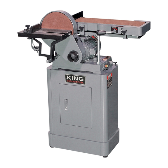
Summary of Contents for King Canada KC-760L
- Page 1 6” X 48” BELT AND 9” DISC SANDER MODEL: KC-760L INSTRUCTION MANUAL COPYRIGHT © 2007 ALL RIGHTS RESERVED BY KING CANADA TOOLS INC.
- Page 2 Warranty does not apply to defects due directly or indirectly to misuse, abuse, negligence or accidents, repairs or alterations and lack of maintenance. KING CANADA shall in no event be liable for death, injuries to persons or property or for incidental, special or consequential damages arising from the use of our products.
-
Page 3: Specific Safety Instructions
GENERAL & SPECIFIC SAFETY INSTRUCTIONS VOLTAGE WARNING: Before connecting the tool to a power source (receptacle, outlet, etc.) be sure the voltage supplied is the same as that specified on the nameplate of the tool. A power source with voltage greater than that for the specified tool can result in SERIOUS INJURY to the user - as well as damage to the tool. - Page 4 ELECTRICAL INFORMATION & TURNING ON YOUR SANDER WARNING! ALL ELECTRICAL CONNECTIONS MUST BE DONE BY A QUALIFIED ELECTRICIAN. FAILURE TO COMPLY MAY RESULT IN SERIOUS INJURY! ALL ADJUSTMENTS OR REPAIRS MUST BE DONE WITH THE MITER SAW DISCONNECTED FROM THE POWER SOURCE.
-
Page 5: Getting To Know Your Sander
13. Lower belt guard 19. Belt angle scale 7. Miter gauge 14. End belt guard SANDER SPECIFICATIONS Model ......................................KC-760L Voltage ....................................120V/240V Amperage ............................10 Amp. @ 120V/5 Amp. @ 240V Motor RPM’s..................................1,740 RPM Prewired ......................................120V Sanding belt size ..................................6” x 48”... -
Page 6: Assembly Instructions
ASSEMBLY INSTRUCTIONS UNPACKING Remove all loose parts from the carton. Carefully lift the sander from the carton and place it on a level work surface. Remove all other items from the carton and follow all of the following assembly, adjustments, operation and maintenance instructions in this manual. - Page 7 ASSEMBLY INSTRUCTIONS INSTALLING 9” PSA SANDING DISC A 9” sanding disc for pressure sensitive adhesive (PSA) backed discs is supplied with this sander. If you wish to install it or any other adhesive 9” sanding disc, follow these instructions; 1. Undo and remove the sanding disc cover lock knob (A) Fig.9 and open the sanding disc cover (B).
- Page 8 ASSEMBLY & ADJUSTMENT INSTRUCTIONS INSTALLING BELT TABLE END SAFETY GUARD The belt table end safety guard (A) Fig. 13 is not installed and should be installed to ensure user safety during sanding operations. If you desire to make internal curve sanding which requires the use of the drum portion of the sanding belt, this end safety guard must not be installed.
-
Page 9: Adjustment Instructions
ADJUSTMENT INSTRUCTIONS ADJUSTING MITER GAUGE ANGLE This miter gauge is used to hold and support the work piece at a chosen angle during a sanding operation. The miter gauge body (A) Fig.17 angle can be adjusted. 1. Loosen lock knob (B) and reposition to the desired angle. 2. - Page 10 ADJUSTMENT INSTRUCTIONS TRACKING THE SANDING BELT Your sander is shipped with the belt tracking mechanism properly adjusted. The sanding belt should run centered and tracking properly between the belt drums. If an adjustment is necessary, follow these instructions; 1. Start the sander. 2.
- Page 11 Sanding long pieces: Do not apply too much pressure on a long damaged. workpiece. Apply only enough pressure so that the sanding belt 2. Sanding disc and belt must be replaced once used. King Canada removes the material. replacement discs and belts of different grits are available at your 2.
-
Page 12: Troubleshooting Chart
TROUBLESHOOTING CHART Problem Probable cause Solution • Voltage drop. • Check power source. • Motor doesn’t start. • Motor short circuit or bad connection. • Check all motor connections. • Check plug or switch for bad insola- • Plug or switch short circuit. tion or contact.


Need help?
Do you have a question about the KC-760L and is the answer not in the manual?
Questions and answers