
Related Manuals for King Canada KC-705L-6


Summary of Contents for King Canada KC-705L-6
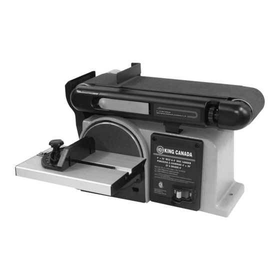
- Page 1 4” x 36” BELT AND 6” DISC SANDER 09/2015 INSTRUCTION MANUAL MODEL: KC-705L-6 COPYRIGHT © 2015 ALL RIGHTS RESERVED BY KING CANADA TOOLS INC.
-
Page 2: Warranty Information
King Canada service center. Contact your retailer or visit our web site at www.kingcanada.com for an updated listing of our authorized service centers. In cooperation with our authorized serviced center, King Canada will either repair or replace the product if any part or parts covered under this warranty which examination proves to be defective in workmanship or material during the warranty period. - Page 3 SAFETY INSTRUCTIONS FOR YOUR BELT AND DISC SANDER SAFETY INSTRUCTIONS FOR BELT AND DISC SANDER that could trap your fingers, Safety is a combination of common sense, staying alert and knowing how your belt disc sander works. Read this manual to understand this •...
- Page 4 SAFETY INSTRUCTIONS FOR YOUR BELT AND DISC SANDER USE THE RIGHT TOOL. Don’t force tool or attachment to do a job it was not designed to do. • When finishing on the disc, always press the workpiece againt the “Down” side of the disc. Sanding against the side coming up from CAUTION: This machine is not designed for heavy deburring op- under the table could damage the work by making it chatter, or tear erations.
-
Page 5: Electrical Information
ELECTRICAL INFORMATION WARNING ALL ELECTRICAL CONNECTIONS MUST BE DONE BY A QUALIFIED ELECTRICIAN. FAILURE TO COMPLY MAY RESULT IN SERIOUS INJURY! ALL ADJUSTMENTS OR REPAIRS MUST BE DONE WITH THE COMPRESSOR DISCONNECTED FROM THE POWER SOURCE. FAILURE TO COMPLY MAY RESULT IN SERIOUS INJURY! POWER SUPPLY PROPERLY GROUNDED OUTLET WARNING: YOUR SANDER MUST BE CONNECTED TO A 120V WALL... -
Page 6: Getting To Know Your Sander
GETTING TO KNOW YOUR SANDER SPECIFICATIONS Model......................................KC-705L-6 Belt ......................................4” x 36” Belt lift ......................................0° - 90° Belt speed.................................... 1,900 SFPM Disc ........................................6” Disc speed .................................... 3,600 RPM Motor ......................................4.3 Amp. Voltage .................................. 110V, 1 phase, 60 Hz Dimensions/weight ..........................17-1/2” x 14” x 10-1/4” / 38 lbs Getting to know your Sander 1. - Page 7 ASSEMBLY MOUNTING BELT AND DISC SANDER TO WORKBENCH If the belt and disc sander is to be used in a permanent location, it should be fastened securely to a firm supporting surface such as a workbench. If mounting to a workbench, holes should be drilled through supporting surface of the workbench.
- Page 8 ASSEMBLY INSTALLING TILTING TABLE FOR VERTICAL BELT SANDING 1. Remove backstop (A) Fig.6, cap screws and washers (B). 2. Remove table assembly (A) Fig.5 by removing table lock knob and washer (B). NOTE: The sanding belt assembly (A) Fig.7 can be raised to vertical position by loos- ening cap screw (B) and raising the assembly.
-
Page 9: Operation
OPERATION USING ON/OFF SWITCH WITH REMOVABLE SAFETY KEY The On/Off switch (A) Fig.11 is used to turn the sander on and off. To turn the sander “On”, move the switch towards the right (On position), to turn the sander “Off”, move the switch towards the left (Off position). -
Page 10: Maintenance And Troubleshooting
MAINTENANCE & TROUBLESHOOTING WARNING: For your own safely, turn switch "OFF" and remove plug from power source outlet before adjusting, maintaining, or lubricating your belt and disc sander. WARNING: To avoid electrocution or fire, any repair to electrical system should be done by qualified service technicians.
Need help?
Do you have a question about the KC-705L-6 and is the answer not in the manual?
Questions and answers