
Related Manuals for King Canada KC-703C


Summary of Contents for King Canada KC-703C
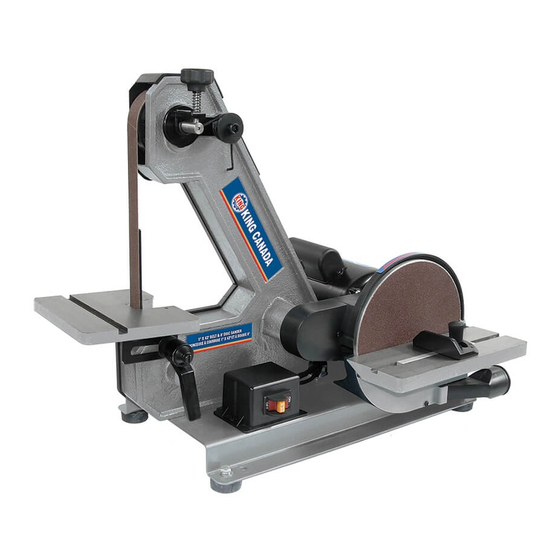
- Page 1 1” x 42” BELT AND 8” DISC SANDER 09/2015 INSTRUCTION MANUAL MODEL: KC-703C COPYRIGHT © 2015 ALL RIGHTS RESERVED BY KING CANADA TOOLS INC.
-
Page 2: Warranty Information
King Canada service center. Contact your retailer or visit our web site at www.kingcanada.com for an updated listing of our authorized service centers. In cooperation with our authorized serviced center, King Canada will either repair or replace the product if any part or parts covered under this warranty which examination proves to be defective in workmanship or material during the warranty period. -
Page 3: Safety Instructions
SAFETY INSTRUCTIONS FOR YOUR BELT AND DISC SANDER SAFETY INSTRUCTIONS FOR BELT AND DISC SANDER • sanding belt narrower than 1 inches. Narrower belts uncover parts Safety is a combination of common sense, staying alert and knowing that could trap your fingers, how your belt disc sander works. - Page 4 SAFETY INSTRUCTIONS FOR YOUR BELT AND DISC SANDER USE THE RIGHT TOOL. Don’t force tool or attachment to do a job it was not designed to do. • When finishing on the disc, always press the workpiece againt the “Down” side of the disc. Sanding against the side coming up from CAUTION: This machine is not designed for heavy deburring op- under the table could damage the work by making it chatter, or tear erations.
-
Page 5: Electrical Information
ELECTRICAL INFORMATION WARNING ALL ELECTRICAL CONNECTIONS MUST BE DONE BY A QUALIFIED ELECTRICIAN. FAILURE TO COMPLY MAY RESULT IN SERIOUS INJURY! ALL ADJUSTMENTS OR REPAIRS MUST BE DONE WITH THE COMPRESSOR DISCONNECTED FROM THE POWER SOURCE. FAILURE TO COMPLY MAY RESULT IN SERIOUS INJURY! POWER SUPPLY USING ON/OFF SWITCH WITH REMOVABLE SAFETY KEY WARNING: YOUR SANDER MUST BE CONNECTED TO A 120V WALL... -
Page 6: Getting To Know Your Sander
GETTING TO KNOW YOUR SANDER SPECIFICATIONS Model ......................................KC-703C Belt ......................................1” x 42” Belt speed.................................... 3,000 SFPM Disc ........................................8” Disc speed .................................... 1,725 RPM Motor ......................................5.8 Amp. Voltage .................................. 120V, 1 phase, 60 Hz Dimensions/weight ..........................25” x 14-3/4” x 19-3/4” / 58 lbs Getting to know your Sander 1. -
Page 7: Mounting Belt And Disc Sander To Workbench
ASSEMBLY Clean all rust protected surfaces with ordinary house hold type grease or spot remover. Do not use; gasoline, paint thinner, mineral spirits, etc. These may damage painted surfaces. Apply a coat of paste wax to the tables to prevent rust. Wipe all parts thor- oughly with a clean dry cloth. - Page 8 ASSEMBLY INSTALLING DRIVE BELT & SANDING DISC UPPER GUARD 1. Position the drive belt & disc sanding upper guard (A) Fig.7 over the pulleys as shown. 2. Line up the two holes in the guard with the holes in the casting of the sanding disc housing, fasten the upper guard (A) using two pan head screws and washers (B) Fig.7 and (A) Fig.8.
- Page 9 ASSEMBLY INSTALLING DISC TO MOTOR SHAFT AND SANDING PAPER 1. Make sure the aluminum disc (A) Fig.11 is perfectly clean of foreign material. NOTE: Only pressure sensitive adhesive sanding sandpaper disc (B) can be installed to the aluminum disc. 2. Peel the protective backing from the supplied sandpaper disc (B), center it on the aluminum disc, and press it in place as shown.
- Page 10 ASSEMBLY INSTALLING SANDING DISC TILTING TABLE & ANGLE POINTER 1. Align the sanding disc table’s (A) Fig.15 curved keyway in the sanding disc housing slot (B). Secure the table in place using the spring loaded lock handle (C) and large washer (D). The sanding disc table can tilt from 0° to 45°. Note: The sanding disc table must be at a distance of about 1/16”...
-
Page 11: Operation & Adjustments
OPERATION & ADJUSTMENTS DISC SANDING Warning! Always make sure the sander is unplugged prior to attempting any installa- tion or changing of parts and accessories. When sanding, always position your workpiece (A) Fig.19 on the downward, rotating side (left side) of the sanding disc as shown. Sanding on the right side of the sanding disc, upward rotating side is dangerous, as your workpiece cannot be controlled and ‘kick-back’... -
Page 12: Changing The Sanding Belt
OPERATION & ADJUSTMENTS CHANGING THE SANDING BELT 1. Remove the rear plastic cover (Diagram #74) from the sanding belt housing by un- screwing the two lock knobs (Diagram #75). See Fig.23. 2. Press down on the tracking knob (A) Fig.24 and hold to compress the spring tension, then slide the sanding belt off the three wheels (A) Fig.23. -
Page 13: Maintenance
OPERATION, ADJUSTMENTS & MAINTENANCE SANDING BELT TABLE ADJUSTMENTS For most sanding operations, the sanding belt table will likely remain at a 90º angle to the sanding belt. A positive stop is provided in the table to ensure fast positioning at 90º...
Need help?
Do you have a question about the KC-703C and is the answer not in the manual?
Questions and answers