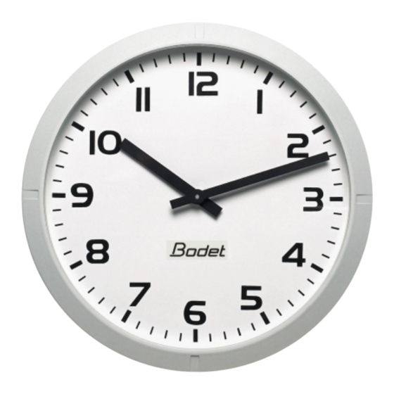
Bodet Profil 960 Installation And Operating Instructions Manual
Led illumination
Hide thumbs
Also See for Profil 960:
- Installation and operating instructions manual (20 pages) ,
- Installation and operation manual (33 pages) ,
- Quick start manual (6 pages)
Table of Contents
Advertisement
Quick Links
Advertisement
Table of Contents

Summary of Contents for Bodet Profil 960
- Page 1 Clock Profil 960 LED il lu mi na tion INSTALLATION AND OPERATING INSTRUCTIONS B.P. 1 49340 TRÉMENTINES FRANCE Tél. : 02 41 71 72 00 Fax : 02 41 71 72 01 www.bodet.com Réf. : 607092 C When receiving goods please chek nothing is broken otherwise make a claim near shipping company.
-
Page 2: Table Of Contents
Table of contents I - INITIAL VERIFICATION ..... . 3 1.1 Un pack ing the clock ....... 3 1.2 Clean ing . -
Page 3: I - Initial Verification
I - INITIAL VERIFICATION Thank you for choosing a BODET clock. This product has been carefully designed for your satisfaction based on ISO9001 quality requirements. We advise you to read this manual thoroughly before attempting to manipulate the clock. Keep this booklet during all the life of your clock, so that you can refer to it each time it is necessary. -
Page 4: Installation
1.3. Recommandations LED lights can be hazardous to the eyes. The LED lighting systems are less energy consuming than other types of lighting and have lifetimes much longer. Partly because of the limited nature of the surface emission, LEDs have luminances at least 1000 times higher than those of a traditional lighting source. -
Page 5: Double Face Clock
having to put the front part of the clock on the ground. - Hang the clock and fix it with M8 screws (4), without locking it, after you have put the wires (between Ø7 and Ø10) through the waterproof pressure joints (5). - Carry out the various connections (external supply : see page 8 and connection to time distribution network : see page 10). -
Page 6: Clock On Keyboard
plate support (6), or through the aperture on the side of the bracket (7). - Carry out the various connections (external supply : page 8 and time distribution network : page 10). - Power the clock and reset the time if necessary. -
Page 7: Setting The Antenna
2.4 Setting the antenna For radio synchronised clocks : The best reception conditions are outside buildings or near windows. Positioning the antenna (perpendicular to the direction of the transmitter) improves reception. The antenna must not be placed on a metal support. As for any radio system, a building with metal structures can cause interference in the reception of the signal. -
Page 8: Power Supply
III - POWER SUPPLY Installation and maintenance of this equipment must be carried out by qualified personnel only. Electrical installation must comply with current standard CEI 364. (NF C15-100 in France for example). The mains supply for the clocks must include a neutral phase circuit breaker 10A C curb, rapidly accessible. -
Page 9: Independent Quartz Clock On Mains
3.2. Independent Quartz clock on mains : Single Face. – Connect mains supply (230VAC) to the terminal (20) of the power supply unit (ref.933006). – Connect the impulses line between the terminal (22) of the power supply unit and the terminal (2) of the clock. The time base is protected by a 0,2AT / 250V fuse (21). -
Page 10: Operating And Time Setting
IV - OPERATING AND TIME SETTING NOTA : to respect the security rules, the time distribution network must be be SELV-type. - The impulses wires should be assembled together near their connecting terminal. 4.1. Impulses slave clock A time distribution network emits only impulses, so that it is necessary to set the clock at the time of this network. -
Page 11: ½ Minute And Minute Serial Receiver
4.1.2. ½ minute and minute serial receiver, - Connect the time distribution network to terminals 1 and 2 on the terminal strip (3). - The terminal 3 of the terminal strip (3) is available. You can use it to connect a double side clock following the diagram opposite. -
Page 12: Afnor/Irig-B Time Signal Reception
4.2. AFNOR/IRIG-B time signal reception - Connect the time signal network to the two upper terminals of the AFNOR receiver card. Check that the dip switch (F) on the electronic card is pushed downwards (ON position). Check that the dip switch (A) is pushed to AFNOR position. AFNOR input Operating principle of AFNOR HM receiver clock :... -
Page 13: Independent Quartz On Mains With Remote Keyboard
– After 1 hour without time signal reception or if the battery voltage drops down, hands are set position 12.00 until power supply recovery. – The synchronous second hand witch is powered by the main 12V 50Hz, will stop immediately. 4.4. -
Page 14: Technical Features
V - TECHNICAL FEATURES Readability : 60m. Dimensions : Profil 960 Single Face Profil 960 Double Face integrated: Ø660 Mounting on bracket... - Page 15 Supply Operating Protection Weight temperatures index -25°C to +70°C IP537 14 kg Profil 960 HM minute // and ½ minute serial receiver -25°C to +70°C IP437 24 kg Profil 960 HM DF minute // and ½ minute serial receiver 230 Volt 50 Hz -25°C to +70°C...
-
Page 16: What To Do If
VI - WHAT TO DO IF...? ...CHECK. What to do if...? … Check. – No synchronisation after the – Check that the type of signal send by the master installation. clock (min, ½ min, AFNOR/ Irig-B) is in accordance with the type programmed in the clock. –...


Need help?
Do you have a question about the Profil 960 and is the answer not in the manual?
Questions and answers