Simrad RD68 Instruction Manual
Fixed dsc vhf radio
Hide thumbs
Also See for RD68:
- Service manual (66 pages) ,
- User manual (52 pages) ,
- Instruction manual (46 pages)
Table of Contents
Advertisement
Advertisement
Table of Contents

Related Manuals for Simrad RD68


Summary of Contents for Simrad RD68
- Page 1 Instruction Manual Simrad RD68 Fixed DSC VHF Radio...
-
Page 2: Table Of Contents
Instruction Manual 1 GENERAL 1.1 Introduction ................1.2 Licensing ................1.3 Entering MMSI numbers ............1.4 Group ID MMSI ..............2 OPERATION 2.1 General .................. 2.2 Rotary controls ..............2.3 Backlighting ................2.4 Changing channels ..............2.4.1 Standard International channels ........2.4.2 Auxiliary &... - Page 3 RD68 VHF 5 APPENDIX 5.1 Operating procedures ............. 5.1.1 Sending a Distress Alert ..........5.1.2 Acknowledging and relaying a Distress Alert .... 5.1.3 Cancelling a Distress Alert ......... 5.1.4 Alerting all vessels within range ......... 5.1.5 Calling a coast radio station ........
-
Page 4: General
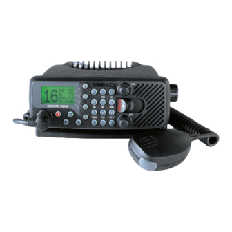
Instruction Manual 1 GENERAL 1.1 Introduction The RD68 is a combined VHF radio and Class D Digital Select- ive Calling (DSC) unit. It supports the latest GMDSS require- ments for non-SOLAS vessels from the International Maritime Organization (IMO). This will enable you to make digitally selected calls, which are quicker and simpler to make than tra- ditional voice calls using channel 16. -
Page 5: Licensing
RD68 VHF 1.2 Licensing Note Prior to use please check the national licensing requirements for operators. In the UK license applications and queries should be made to the following authority: Ship Radio Licencing Radio Licencing Centre The Post Office PO Box 1495 Bristol BS99 3QS Website: www.radiolicencecentre.co.uk/rlc... -
Page 6: Entering Mmsi Numbers
RD68 when the radio is first set up, otherwise the DSC func- tions cannot be accessed. Note If the boat or the RD68 are subsequently sold, the radio must be returned to an authorized Simrad agent for the MMSI number to be erased and the new owner’s MMSI number entered. -
Page 7: Group Id Mmsi
It is important that the MMSI entered is checked care- fully, as it can only be entered once. To change the MMSI number after it has been programmed, the unit must be returned to an authorized Simrad Dealer to erase the existing number. 1.4 Group ID MMSI For boats that are part of a flotilla, racing fleet, or other group, a... -
Page 8: Operation
Instruction Manual 2 OPERATION 2.1 General The RD68 VHF is very simple to operate, with the controls falling into five groups: 1. The rotary Volume (On/Off) & Squelch controls. 2. The alphanumeric keypad used to select the channel, MMSI number, etc. -
Page 9: Backlighting
(by pressing E), Scan the radio will revert to the original channel Note To select channels, the RD68 will need to be in Radio mode. If in DSC mode, press the RAD softkey before entering the chan- nel number. E03912 Issue 2.0... -
Page 10: Auxiliary & Private Channels
Instruction Manual 2.4.2 Auxiliary & Private channels This function is used to select channels which are not part of the standard International channel set, for example, channels M and M2 in the UK, or the US Wx Weather channels. Note Standard availability of channels includes M &... -
Page 11: Transmit Power
RD68 VHF 2.5 Transmit power This function allows toggling of the transmit power between 25W (Hi) and 1W (Lo) for short range transmissions, for exam- ple, when in a marina. This preserves battery power. 1 2 : 4 2 H H i i... - Page 12 Instruction Manual 1 2 : 4 3 C C a a l l l l Menu SELECTING CALL TYPE MANUAL ENTRY Press Type to scroll through To manually enter an MMSI the different types of calls number (Routine call): (see also p. 16): 1 2 : 4 3 1 2 : 4 3 Use key to...
- Page 13 RD68 VHF 1 2 : 4 4 C C a a l l l l Menu MMSI DIRECTORY VOICE CHANNEL SELECTION Use the directory (see sec- To specify which channel is to be tion 3.4) to select a com- used in voice communication...
-
Page 14: Making A Distress Alert Call
Instruction Manual 2.7 Making a Distress Alert call WARNING This call should only be made if the vessel is in a genuine distress situation. It is an offense to send a Distress Alert call if the vessel or crew are not in grave and imminent danger (see section 5.1). - Page 15 NMEA interface, then the display will allow this data to be entered manually (refer to section 3.2 for more details). After the Distress Alert has been sent, the RD68 will tune to channel 16 and will automatically repeat the alert approximately...
-
Page 16: Receiving A Dsc Call
Instruction Manual 2.8 Receiving a DSC call When a call is received, the RD68 will ring and the display will show the call information. Press Ack (for individual calls requesting acknowledgment only) or OK to cancel and switch to the working channel. Press Stop to cancel ring only. -
Page 17: Dual Watch
C C h h 1 1 6 6 D D / / W W D D / / W W The RD68 will monitor the working channel and the priority channel sequentially Note Normal VHF functions will not be available when in Dual Watch mode. -
Page 18: Tri-Watch
Instruction Manual 2.10 Tri-Watch Tri-Watch operates on the same principle as Dual Watch, but this function scans between the working channel, priority chan- nel, and the User channel. For more information on the User channel and how it is specified, please refer to section 2.13. 1 2 : 5 3 T T / / W W Select a working channel... -
Page 19: Scan Mode
RD68 VHF 2.11 Scan mode The Scan function cycles the RD68 sequentially through each enabled channel, pausing when a signal is detected. 1 2 : 5 4 Lite S S c c a a n n 1 2 : 5 4... -
Page 20: Memory Scan
Instruction Manual To re-enable an inhibited channel into the scan cycle, repeat sequence 2: 1 2 : 5 5 Select channel to be enabled S S c c a a n n then press and hold Scan E E n n a a (double beep) S S c c a a n n Press and... -
Page 21: Add/Remove Channels From Memory Scan
RD68 VHF 2.12.1 Add/remove channels from Memory Scan To add a channel to the Memory Scan cycle: 1 2 : 5 7 Lite Select the required Scan channel 1 2 : 5 7 M M / / S S M M / / S S... -
Page 22: Priority & User Channel Select
2.13 Priority & User channel select The priority channel (usually Ch16, depending on the configura- tion of the RD68) can be accessed immediately by pressing 16. This will cancel any function currently in operation. The User channel is a programmable priority channel which is... -
Page 23: Viewing The Call Log
RD68 VHF 2.14 Viewing the call log The last 16 incoming DSC calls are logged by the RD68 and can be viewed later (this function will not be displayed if no calls have been received). 1 2 : 5 8... -
Page 24: Miscellaneous Functions
Instruction Manual 3 MISCELLANEOUS FUNCTIONS 3.1 Adjusting the LCD contrast 1 3 : 0 0 Call M M e e n n u u 1 3 : 0 0 L L C C D D Posn More ▲ ▼ Press keys to 1 3 : 0 0 Contrast... -
Page 25: Entering Position And Time Manually
RD68 VHF 3.2 Entering position and time manually The boat’s position and the time (transmitted as part of a Dis- tress Alert call) would normally be given by an interfaced GPS. If this is not available, the information can be manually entered:... - Page 26 This option will not be available if position and time data is being received via the NMEA input. If this option is used, the POSITION RD68 will request that IS OVER the position and time be 4 HOURS updated regularly P P o o s s n n E03912 Issue 2.0...
-
Page 27: Entering Local Time
RD68 VHF 3.3 Entering local time When a GPS is connected to the RD68 via the NMEA interface, the display will show the UTC (GMT) time in the top right- hand corner. This can be changed to the local time if required:... -
Page 28: Viewing The Directory
M M e e n n u u 3.4 Viewing the directory The directory allows up to 16 MMSI numbers to be stored in the RD68’s memory. These can then be recalled when making an Individual Routine call: 1 8 : 0 3... -
Page 29: Adding An Entry To The Directory
RD68 VHF 1 8 : 0 4 Directory N N e e x x t t Excalibur Edit 002321167 1 8 : 0 4 Directory Back Saucy Sue Next 002320588 Edit 3.4.1 Adding an entry to the directory 1 8 : 0 5... -
Page 30: Editing/Deleting An Entry
Instruction Manual 3.4.2 Editing/deleting an entry To edit an existing entry: 1 8 : 0 6 The main directory Directory screen shows the V V i i e e w w Used 05/16 number of entries 1 8 : 0 6 Directory Next Excalibur... - Page 31 RD68 VHF To delete an entry from the directory: 1 8 : 0 6 Directory V V i i e e w w Used 05/16 1 8 : 0 7 Directory Next Excalibur E E d d i i t t...
-
Page 32: Disabling The Key Beep
Instruction Manual 3.5 Disabling the key beep All key presses on the RD68 are normally confirmed by a “beep” – this feature can be disabled: 1 8 : 0 7 Call M M e e n n u u 1 8 : 0 7... -
Page 33: Second Country Mode
RD68 VHF 3.6 Second country mode In countries where it is permitted, the RD68 can operate on a secondary set of channels, such as the USA channels: Radio switched off Press and hold 1 8 : 0 7 U U S S A A... -
Page 34: Installation
Although the RD68 radio is waterproof when flush mounted, it is recommended that it is not installed where it will be exposed to continuous direct sunlight, as this will eventually damage the LCD display. - Page 35 RD68 VHF The radio is fixed to the bracket using a simple clamp arrange- ment. The peg on the left side of the radio is slotted into the hole in the bracket. The clamp on the right side of the radio can then be slid into the slotted aperture on the bracket and tight- ened to hold the radio firmly in place (Fig 4.3).
- Page 36 Instruction Manual The RD68 has five electrical connections – the handset/fistmike socket is on the front panel below the LCD display (Fig 4.4A). The other four are situated on the back of the case: the antenna socket is on the left (Fig 4.4B); DC power is supplied to the set via a two-core flying lead (Fig 4.4C);...
-
Page 37: Antenna Installation
For NMEA interfacing to an external navigation source (e.g. a GPS, Loran or chartplotter) the RD68 is supplied with a 1 m cable assembly which plugs into the lead at the back of the radio. The other end is connected to the navigator as follows:... - Page 38 Instruction Manual The most popular antennas for marine use are 1 m (3 ft 3 in) long. On sailboats these are usually mounted on the masthead, where the length of the antenna keeps it clear from the naviga- tion lights and windvanes, etc. This type of antenna can also be mounted on the cockpit roof or garage of power boats.
-
Page 39: Electrical Interference Suppression
Note If the RD68 detects a problem with the antenna or antenna con- nections, the display will show ANT when the PTT key is press- ed. To avoid possible damage to the radio the antenna should be checked immediately for any damage or poor connection. -
Page 40: Appendix
Instruction Manual 5 APPENDIX 5.1 Operating procedures The following operating procedure summary has been proposed by the UK Maritime and Coastguard Agency. It is not exhaus- tive and should not be regarded as a replacement for informa- tion provided by the proper two-day VHF/DSC training course required for all UK VHF license holders. -
Page 41: Cancelling A Distress Alert
5.1.3 Cancelling a Distress Alert If a DSC Distress Alert is sent accidentally, cancel it immediate- ly on the RD68 by pressing the C button to prevent repeats, then make the following announcement on channel 16: “This is (name of vessel, callsign, MMSI)”... -
Page 42: Transmission Range
Fig 5.1 - VHF transmission range The typical ship-to-ship range of a fixed VHF radio, such as the RD68, with a masthead antenna will be approximately 20 km (12 miles). This will increase as height above sea level increas- es, or if the other radio user’s antenna is at a greater height –... -
Page 43: Channel Frequencies
RD68 VHF 5.4 Channel frequencies Note Ch 0 will only be made available in the UK to Coastguard users with written authorization. Channel 70 is the designated Digital Selective Calling (DSC) channel and may not be used for voice transmissions. -
Page 44: Troubleshooting
Instruction Manual 5.5 Troubleshooting Symptom Possible Cause Remedy Unit will not switch on * Faulty connection to power * Check power connection * Fuse has blown * Replace fuse and check power supply current Scan or Memory Scan is * Noise on the channel is holding * Increase squelch level locking on a channel the scan... -
Page 45: Accessories
External speaker impedance ......8Ω *Contact your local Simrad Technical Dealer for further details. -
Page 46: Dimensions
Instruction Manual 5.8 Dimensions 158 mm (6.2 in) 185 mm (7.4 in) 47 mm (1.8 in) 55mm (2.2 in) 213 mm (8.4 in) E03912 Issue 2.0...
Need help?
Do you have a question about the RD68 and is the answer not in the manual?
Questions and answers